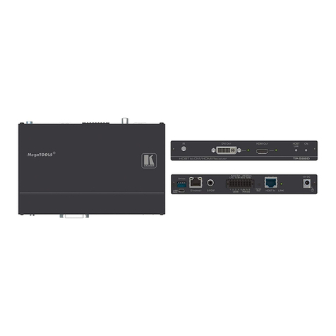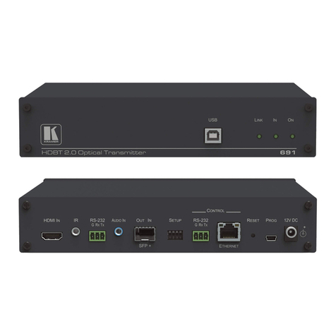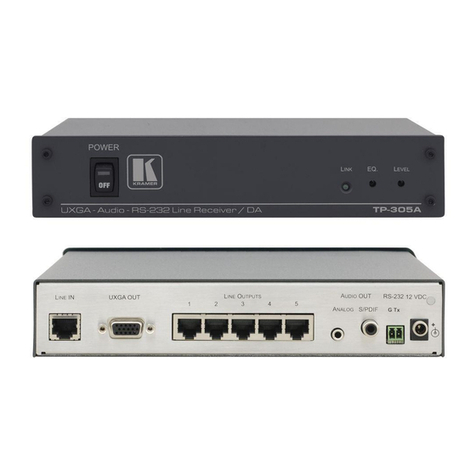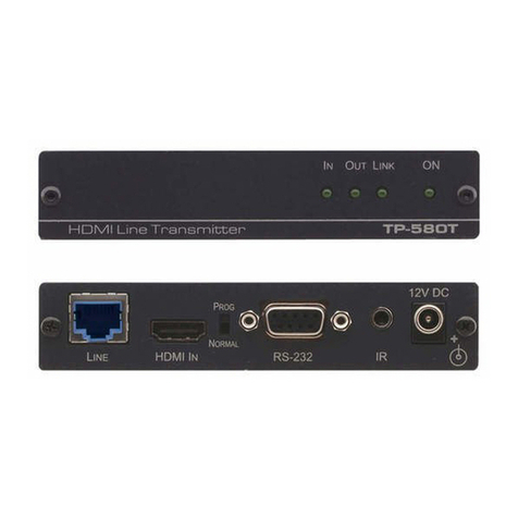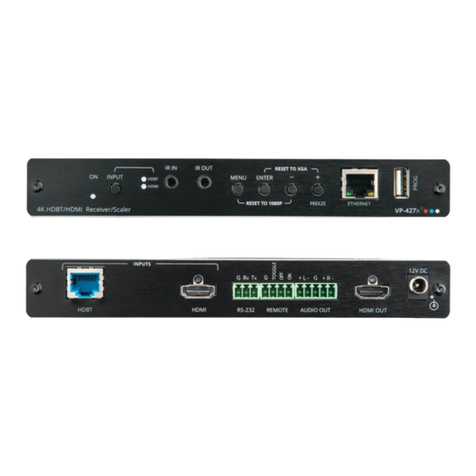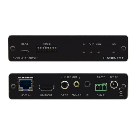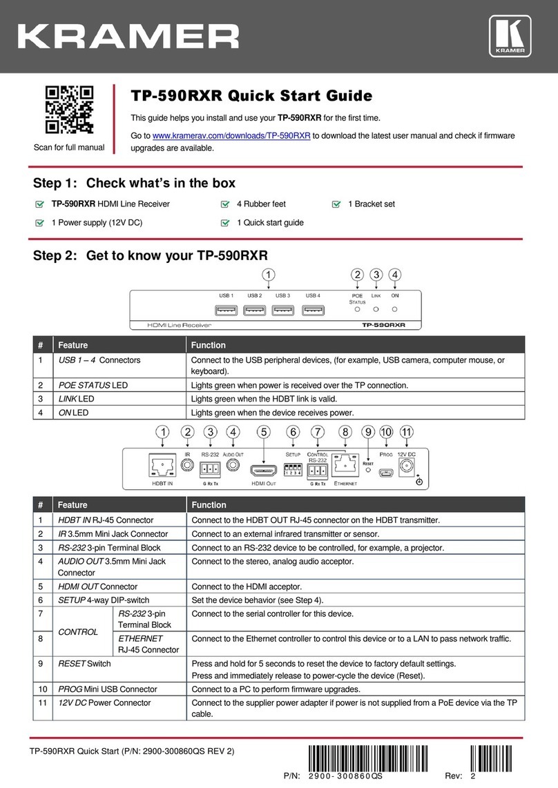
The DIP-switches are used to:
•Set the HDBT range.
•Set the compression levels and resolutions.
•Enable RS-232 signal extension.
•Upgrade the firmware.
•Determine IR signal pass-through.
All the DIP-switches are set to OFF (up) by default.
To use your TP-583Txr or TP-583Rxr with any other standard HDBaseT
extender (without compression), verify that DIP-switch 1B is OFF (up).
OFF (up) –HDBaseT normal range.
ON (down) –HDBaseT ultra-long range (to enable increased range at a
reduced bandwidth).
The ultra-long range mode is activated when on at least one of
the devices DIP-switch 1 is set to ON.
Set the Compression Level
(for extended range)
OFF (up) –Standard compression level.
ON (down) –High compression level for additional extension.
B –DIP-switch Settings
Changes to DIP-switches 2B and 3B only take effect after power cycling the device.
Define Compressed
Resolutions
OFF (up) –Compress signal resolutions higher than 1080p.
ON (down) –Compress all signal resolutions to enable extended reach.
OFF (up), OFF (up) –Embed RS-232 data and control signals over the
extension line.
Other DIP-switch settings are reserved for firmware upgrade. For
OFF (up) –Pass-through the IR signal to the IR port via IR cable.
ON (down) –Add IR modulation to the IR output signal (applies only when
the IR port is connected to an IR emitter cable).
The IR Pass-through DIP-switch setup depends on the IR control
configuration. We recommend that you test which position best
suits your application.
Step 5: Connect the power
Connect the 12V DC power adapter to TP-583Txr/TP-583Rxr and plug it into the mains electricity.
Safety Instructions
There are no operator serviceable parts inside the unit.
Use only the Kramer Electronics power adapter that is provided with the unit.
Disconnect the power and unplug the unit from the wall before installing.
See www.KramerAV.com for updated safety information.
