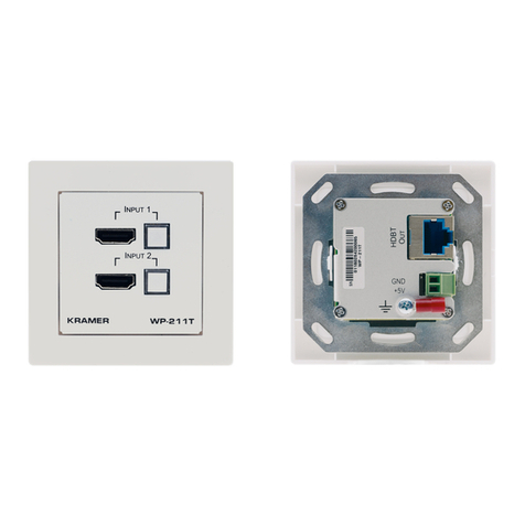
Kramer WP-20CT User manual

Kramer Electronics Ltd.
WP-20CT –Contents
i
Contents
Introduction 1
Getting Started 1
Overview 2
Typical Applications 3
Defining WP-20CT Wall-Plate HDBaseT Auto Switcher/Transmitter 4
Mounting WP-20CT 6
Connecting WP-20CT 8
Connecting to WP-20CT via RS-232 9
Wiring RJ-45 Connectors 9
Connecting USB-C Port Directly to PC 9
Principles of Operation 12
Input Auto-Switching 12
Maestro Built-in Automation Configuration 13
Operating and Controlling WP-20CT 15
Browsing WP-20CT Web Pages 16
Switching Input to Output 16
Muting and Adjusting Audio Output 17
Turning Off Video Output 18
Configuring Auto-Switching Mode 18
Defining Signal Timeout Settings 19
Configuring AV Settings 20
Copying EDID 21
Changing Device Name 22
Setting Auto Standby Delay 23
Exporting and Importing a Configuration File 23
Resetting Device 24
Configuring Network Settings 24
Configuring Time and Date 25
Changing Web Pages Access Password 25
Setting Web Pages Auto Logoff Timeout 26
Configuring Device Automation 26
Maintaining Device 31
Upgrading Firmware 31
Monitoring Device Status 31
Technical Specifications 33
Default Communication Parameters 34
Default Control and Automation Settings 34
Default EDID 36
Protocol 3000 39
Understanding Protocol 3000 39
Protocol 3000 Commands 40
Result and Error Codes 43

Kramer Electronics Ltd.
WP-20CT –Introduction
1
Introduction
Welcome to Kramer Electronics! Since 1981, Kramer Electronics has been providing a world
of unique, creative, and affordable solutions to the vast range of problems that confront the
video, audio, presentation, and broadcasting professional on a daily basis. In recent years, we
have redesigned and upgraded most of our line, making the best even better!
Getting Started
We recommend that you:
•Unpack the equipment carefully and save the original box and packaging materials for
possible future shipment.
•Review the contents of this user manual.
Go to www.kramerav.com/downloads/WP-20CT to check for up-to-date user manuals,
application programs, and to check if firmware upgrades are available (where appropriate).
Achieving Best Performance
•Use only good quality connection cables (we recommend Kramer high-performance,
high-resolution cables) to avoid interference, deterioration in signal quality due to poor
matching, and elevated noise levels (often associated with low quality cables).
•Do not secure the cables in tight bundles or roll the slack into tight coils.
•Avoid interference from neighboring electrical appliances that may adversely influence
signal quality.
•Position your Kramer WP-20CT away from moisture, excessive sunlight, and dust.
Safety Instructions
Caution:
•This equipment is to be used only inside a building. It may only be connected to other
equipment that is installed inside a building.
•For products with relay terminals and GPIO ports, please refer to the permitted rating
for an external connection, located next to the terminal or in the User Manual.
•There are no operator serviceable parts inside the unit.
Warning:
•Use only the power cord that is supplied with the unit.
•Disconnect the power and unplug the unit from the wall before installing.
•Do not open the unit. High voltages can cause electrical shock! Servicing by qualified
personnel only.
•To ensure continuous risk protection, replace fuses only according to the rating
specified on the product label which is located on the bottom of the unit.

Kramer Electronics Ltd.
WP-20CT –Introduction
2
Recycling Kramer Products
The Waste Electrical and Electronic Equipment (WEEE) Directive 2002/96/EC aims to reduce
the amount of WEEE sent for disposal to landfill or incineration by requiring it to be collected
and recycled. To comply with the WEEE Directive, Kramer Electronics has made
arrangements with the European Advanced Recycling Network (EARN) and will cover any
costs of treatment, recycling and recovery of waste Kramer Electronics branded equipment on
arrival at the EARN facility. For details of Kramer’s recycling arrangements in your particular
country go to our recycling pages at www.kramerav.com/il/quality/environment.
Overview
Congratulations on purchasing your Kramer WP-20CT Wall-Plate HDBaseT Auto
Switcher/Transmitter. WP-20CT is an intelligent 2x1 automatic wall-plate switcher
transmitter over long-reach HDBaseT for 4K USB-C and HDMI™video signals. WP-20CT
offers an intelligent switching experience with built-in Maestro room control and the standard
priority / last-connected switching function based on active video signal detection.
•High Performance Switcher Transmitter –Professional HDBaseT switcher transmitter for
providing long-reach signals over twisted pair copper infrastructures. This switcher
transmitter is a standard transmitter that can be connected to any market-available
HDBaseT-compliant extension product.
•Simple and Powerful Maestro Room Control –Out-of-the-box configured room control
for a typical meeting room setup, and intuitive user interface enables you to control your
meeting room elements. Room devices are controlled, locally or remotely via HDBaseT,
right out-of-the-box by an extensive range of triggers, including input/output connectivity
and routing. By minimizing user intervention, Maestro room control saves meeting prep
time and minimizes human error before presentations.
•Automatic Display Operation –Part of the out-of-the-box Maestro configured room
automation. Meeting presentation is simplified by automatically turning ON/OFF a CEC-
enabled display when the presentation source is plugged in / unplugged with user-
defined shut-down delay.
•BYOD Ease and Convenience –Connect any DP-Alt-Mode-capable USB-C device as
an AV presentation source, while providing the connected device (if PD-2.0-capable)
with up to 60 watts of power.
•Plug & Play Auto Switcher –Automatically plays the switched user device source signal
on the connected display according to user-configured preferences, such as priority or
last-connected input. When the user manually switches, the auto switching is overridden.
•HDMI™ Signal Switching – HDCP 2.3 compliant, supporting deep color, x.v.Color™, lip
sync, HDMI uncompressed audio channels, Dolby TrueHD, DTS-HD, 2K, 4K, and 3D as
specified in HDMI 2.0.
•I-EDIDPro™ Kramer Intelligent EDID Processing™ – Intelligent EDID handling,
processing, locking and pass-through algorithm ensures plug & play operation for HDMI
source and display systems.
Kramer Electronics Ltd.
WP-20CT –Introduction
3
•Multi-channel Audio Switching –Up to 8 channels of digital stereo uncompressed signals
for supporting studio-grade surround sound.
•Audio De-embedding –The digital audio signal passing-through to the output, is de-
embedded, converted to an analog signal and sent to the stereo analog audio output.
This enables playing the audio on locally connected speakers, in parallel to playing it on
the speakers connected to the AV acceptor device (such as TVs with speakers).
•Bidirectional RS-232 Extension –Serial interface data flows in both directions, allowing
data transmission and device control.
•Reliable PoE (Power over Ethernet) Powering –Auto-senses the HDBaseT extension
line PoE status, it accepts power from a remote PoE provider such as a PoE matrix, with
optional mains powering from connected power adapter.
•Cost-effective Maintenance and Management –Status LED indicators for Power, HDMI,
and HDBaseT ports facilitate easy local maintenance and troubleshooting. Local device
management using built-in web interface via the USB-C connection. Local firmware
upgrade via USB-C and RS-232 connection tool ensure lasting, field-proven deployment.
•Easy Installation –Compactly fits into standard US, EU, and UK 1 gang in-wall box size,
supporting decorative integration with room deployed user interfaces such as electrical
switches. Wall-plate installation is fast and cost-effective via a single twisted pair cable,
providing both video signal and power (PoC) connections.
Typical Applications
WP-20CT is ideal for the following typical applications:
•Podium-mounted switcher in lecture halls, training rooms, auditoriums, and hospitality
applications.
•Wall-mounted switcher within any AV distribution system.
•Multimedia and presentation source selection in various enterprise applications.

Kramer Electronics Ltd.
WP-20CT –Defining WP-20CT Wall-Plate HDBaseT Auto Switcher/Transmitter
4
Defining WP-20CT Wall-Plate
HDBaseT Auto
Switcher/Transmitter
This section defines WP-20CT.
Figure 1: WP-20CT Wall-Plate HDBaseT Auto Switcher/Transmitter Front Panel
#
Feature
Function
HDMI™ IN Connector
Connects to an HDMI source.
USB-C LED
•Off –an input source is not connected.
•Blue –an active signal is detected on the input.
•Blue, flashing –the source is connected but an active
signal is not detected.
HDMI LED
STATUS LED
•Off –the device is not receiving power.
•Red –the powered device is inactive or booting.
•Green –the device is active and powered via power
supply.
•Orange –the device is active and powered via PoE.
•Green or orange (depending on power source), flashing
slowly –the device is in the power-save standby mode.
•Green or orange (depending on power source), fast-
flashing –firmware is downloading in the background.
1
2
3

Kramer Electronics Ltd.
WP-20CT –Defining WP-20CT Wall-Plate HDBaseT Auto Switcher/Transmitter
5
#
Feature
Function
USB-C IN Port
Connect to a USB-C source (that supports DisplayPort
Alternate Mode).
•When powered by a Kramer 20V power supply (optional),
charges sources (that support USB Power Delivery 2.0)
up to 60W.
•Use to access WP-20CT embedded web pages via
connected browser.
12V/20V Power Supply 2-pin
Terminal Block Connector
Connect to the power supply (required for USB charging).
Connect GND to GND, +12V/20V to +12/20V.
•If you need to charge a device via the USB-C port, use
Kramer 20V power supply (optional).
HDBT OUT PoE RJ-45
Connector
Connect to the HDBaseT IN port on a PoE-provider receiver
(for example, TP-789R) or a receiver (for example, TP-580R).
•When WP-20CT is connected to a PoE providing receiver,
it is not necessary to connect a power supply, unless the
USB-C charging feature is used which requires the
Kramer 20V power supply.
CONTROL RS-232 3-pin
Terminal Block Connector (Tx,
Rx, and common G)
Connect to a controller to control the device.
EXTD RS-232 3-pin Terminal
Block Connector (Tx, Rx, and
common G)
Connect to a controller to extend an RS-232 bi-directional
signal (even if no A/V signal is extended).
AUDIO OUT 3-pin Terminal Block
Connector
Connect to an unbalanced analog audio acceptor.
Ring Tongue Terminal Grounding
Screw
Connect to grounding wire (optional).
4
5
6
7
8
9
10

Kramer Electronics Ltd.
WP-20CT –Mounting WP-20CT
6
Mounting WP-20CT
This section provides instructions for mounting WP-20CT. Before installing, verify that the
environment is within the recommended range:
•Operation temperature –0to 40C (32 to 104F).
•Storage temperature –-40to +70C (-40 to +158F).
•Humidity –10% to 90%, RHL non-condensing.
Before mounting, connect the HDBaseT cable and power
Warning:
•Ensure that the environment (e.g., maximum ambient temperature & air flow) is
compatible for the device.
•Avoid uneven mechanical loading.
•Appropriate consideration of equipment nameplate ratings should be used for avoiding
overloading of the circuits.
•Reliable earthing of rack-mounted equipment should be maintained.
To mount WP-20CT:
Insert the device into the in-wall box (note that first you need to connect the HDBaseT cable
and power) and connect the parts as shown in the illustrations below:
EU/UK Version
US-D Version
DECORA® design frames are included in US-D models. DECORA® is a registered
trademark of Leviton Manufacturing Co., Inc.

Kramer Electronics Ltd.
WP-20CT –Mounting WP-20CT
7
We recommend that you use any of the following standard 1 Gang in-wall junction boxes (or
their equivalent):
•US-D: 1 Gang US electrical junction boxes.
•EU: 1 Gang in-wall junction box, with a cut-hole diameter of 68mm and depth that can
fit in both the device and the connected cables (DIN 49073).
•UK: 1 Gang in-wall junction box, 75x75mm (W, H) and depth that can fit in both the
device and the connected cables
(BS 4662 or BS EN 60670-1 used with supplied spacers and screws).

Kramer Electronics Ltd.
WP-20CT –Connecting WP-20CT
8
Connecting WP-20CT
Always switch off the power to each device before connecting it to your WP-20CT.
Figure 2: Connecting to the WP-20CT Rear Panel
To connect WP-20CT as illustrated in the example in Figure 2:
1. Connect the HDMI source (for example, a Blu-ray player) to the HDMI IN connector .
2. Connect the USB-C source (for example, a tablet) to the USB-C IN connector .
3. Connect a controller (for example, RC-306 control keypad) to the Control RS-232
connector to control WP-20CT and to the EXTD RS-232 connector to control a
device on the receiver side via serial communication.
4. Connect the HDBaseT OUT connector to the HDBaseT input of a PoE-provider
receiver (for example, TP-789R) or a non-PoE receiver (for example, TP-580R).
5. Connect an RS-232-controlled device (for example, a projector) to the receiver HDMI
input and RS-232 connector.
6. Connect the included 12V power supply to the 12V/20V connector for powering the
unit when connected to a non-PoE receiver.
-OR-
Connect an optional PS-2006-O 20V/6A Kramer power supply to the
12V/20V connector to enable the USB-C charging feature.
1
4
7
8
6
6
6

Kramer Electronics Ltd.
WP-20CT –Connecting WP-20CT
9
Connecting to WP-20CT via RS-232
You can connect to WP-20CT via an RS-232 connection using, for example, a PC.
WP-20CT features an RS-232 3-pin terminal block connector allowing the RS-232 to control
WP-20CT.
Connect the RS-232 terminal block on the rear panel of WP-20CT to a PC/controller, as
follows:
From the RS-232 9-pin D-sub serial port connect:
•Pin 2 to the TX pin on the WP-20CT RS-232 terminal block
•Pin 3 to the RX pin on the WP-20CT RS-232 terminal block
•Pin 5 to the G pin on the WP-20CT RS-232 terminal block
RS-232 Device WP-20CT
Wiring RJ-45 Connectors
This section defines the HDBT pinout, using a straight pin-to-pin cable with RJ-45 connectors.
For HDBaseT cables, it is recommended that the cable ground shielding be
connected/soldered to the connector shield.
EIA /TIA 568B
PIN
Wire Color
1
Orange / White
2
Orange
3
Green / White
4
Blue
5
Blue / White
6
Green
7
Brown / White
8
Brown
Connecting USB-C Port Directly to PC
You can connect the USB-C IN port of WP-20CT directly to the USB port on your PC using a
USB-C to USB-C cable. This enables you to configure and operate the device using the
embedded web pages (see Operating and Controlling WP-20CT on page 15).
After connecting WP-20CT to the USB-C port, configure your PC as follows:
1. Click Start > Control Panel > Network and Sharing Center.
2. Click Change Adapter Settings.
3. Highlight the ASIX network adapter to connect to the device and click Change settings
of this connection.
13

Kramer Electronics Ltd.
WP-20CT –Connecting WP-20CT
10
The Ethernet Properties window for the selected network adapter appears as shown in
Figure 3.
Figure 3: Local Area Connection Properties Window
4. Highlight Internet Protocol Version 4 (TCP/IPv4) depending on the requirements of
your IT system.
5. Click Properties.
The Internet Protocol Properties window relevant to your IT system appears as shown in
Figure 4 or Figure 5.
Figure 4: Internet Protocol Version 4 Properties Window

Kramer Electronics Ltd.
WP-20CT –Connecting WP-20CT
11
Figure 5: Internet Protocol Version 6 Properties Window
6. Select Use the following IP Address for static IP addressing and fill in the IP address
and Subnet mask as shown in Figure 6.
You can use any IP address in the range 192.168.1.1 to 192.168.1.255 (excluding
192.168.1.39) that is provided by your IT department.
Figure 6: Internet Protocol Properties Window
7. Click OK.
8. Click Close.
9. Browse to the fallback IP address or default hostname of the device.

Kramer Electronics Ltd.
WP-20CT –Principles of Operation
12
Principles of Operation
Input Auto-Switching
Input selection is set via the web pages (see Configuring Auto-Switching Mode on page 18) to
one of the following modes:
•Manual
•Last connected
•Priority
By default, switching is set to Last connected.
When in Manual mode, note the following:
•Switching to an unconnected input, results in a blank screen on the output.
•Manual switching overrides auto-switch mode.
In manual mode, select an input by:
•Sending RS-232 serial commands control (see Protocol 3000 Commands on page 40).
•Using the embedded web pages (see Browsing WP-20CT Web Pages on page 16).
In auto-switching mode, switching selection is performed based on either last connected or
priority input:
•In last connected mode, if the signal on the current input is lost, WP-20CT automatically
selects the last connected input (the delay depends on a configurable timeout).
•In priority mode, when the input sync signal is lost for any reason, the input with a live
signal and next in priority is selected automatically, (the delay depending on the
configurable signal-lost timeout, (see Defining Signal Timeout Settings on page 19).

Kramer Electronics Ltd.
WP-20CT –Principles of Operation
13
Maestro Built-in Automation Configuration
WP-20CT built-in Maestro automation enables configuring triggers to simply create a
sequence of actions that are carried out following trigger activation (see Configuring Device
Automation on page 26).
Thanks to out-of-the-box default configuration, WP-20CT is ready to control the following
typical room configuration that can be controlled via several Maestro triggers.
Figure 7: Typical Room Configuration
This room includes a meeting-room table, a presentation area, and so on, as follows:
On the meeting table:
•WP-20CT mounted onto a TBUS-10XL table mount.
•Various BYOD sources, of which one or two are connected to the
WP-20CT HDMI port (for example, a laptop) and/or the USB-C port
(for example, a tablet).
•A KT-107 touch panel supporting Kramer Control controller and
connected to the LAN.
On the Wall:
•Tavor 6-O wall-mounted speakers connected to WP-20CT.
In the presentation
area:
•TP-789R receiver, connected via HDBT to WP-20CT.
•A CEC-enabled display connected to the TP-789R HDMI output.
In the room:
•The window blinds, projector screen, lighting, and air conditioning are
connected to GPIO/relay ports on the FC-28 IP control gateway.
LAN connections
•KT-107 Kramer Control touch panel controller to FC-28 IP control
gateway and a Kramer Network management system.
WP-20CT, built-in Maestro configuration enables almost immediate control over these
elements for different scenarios, once all the elements in the room are connected (with
minimal settings via built-in Maestro automation embedded web pages, such as device-
specific IP addresses, see Configuring Device Automation on page 26).
KT-107 and FC-28 (in the optional control and management system) are not included in
the built-in Maestro configuration, and should be configured separately.

Kramer Electronics Ltd.
WP-20CT –Principles of Operation
14
For example, an active input that is detected, is a trigger (First On) for starting a presentation.
Once the input signal is detected, the Presentation Start, built-in script, runs a series of
actions such as unmuting the audio and video outputs, turning the display ON via CEC,
lowering the screen rolling the blinds down, etc.
In this example, the display is turned on via the HDBT CEC channel connection through the
TP-789R receiver, and audio and video are unmuted by the internal port.
Factory default triggers, Scripts, actions and ports are listed in Default Control and
Automation Settings on page 34.

Kramer Electronics Ltd.
WP-20CT –Operating and Controlling WP-20CT
15
Operating and Controlling
WP-20CT
You can operate WP-20CT using the embedded web pages, by connecting to WP-20CT with
a computer via the USB-C connector (see Connecting USB-C Port Directly to PC on page 9).
WP-20CT enables you to do the following:
•Browsing WP-20CT Web Pages on page 16.
•Switching Input to Output on page 16.
•Muting and Adjusting Audio Output on page 17.
•Turning Off Video Output on page 18.
•Configuring Auto-Switching Mode on page 18.
•Defining Signal Timeout Settings on page 19.
•Configuring AV Settings on page 20.
•Copying EDID on page 21.
•Changing Device Name on page 22.
•Setting Auto Standby Delay on page 23.
•Exporting and Importing a Configuration File on page 23.
•Resetting Device on page 24.
•Configuring Network Settings on page 24.
•Configuring Time and Date on page 25.
•Changing Web Pages Access Password on page 25.
•Setting Web Pages Auto Logoff Timeout on page 26.
•Configuring Device Automation on page 26.

Kramer Electronics Ltd.
WP-20CT –Operating and Controlling WP-20CT
16
Browsing WP-20CT Web Pages
If a web page does not update correctly, clear your Web browser’s cache.
If security is enabled, the Login window appears.
Figure 8: Embedded Web Pages Login Window
10.Enter the Username (default = Admin) and Password (default = Admin) and click
Sign in.
The Main > AV Routing page appears.
Figure 9: Embedded Web Pages Main > AV Routing Page
11.Click the Navigation Pane on the left side of the screen to access the relevant web page.
Hover over the icons on the navigation pane to hide/show the names of the pages.
Switching Input to Output
WP-20CT enables you to switch one of the two inputs to the output.
The AV Routing page shows the following information:

Kramer Electronics Ltd.
WP-20CT –Operating and Controlling WP-20CT
17
•Name of each input and output (to change the name, see Configuring AV Settings
on page 20).
•Connection status of each input and output –The indicator next to the name lights
green when an active input or output is connected.
•Switching status –The input that is currently connected to the output shows a green
checkmark in the column next to it.
To switch an input to the output:
1. Go to the Main > AV Routing page.
Figure 10: Main > AV Routing Page
2. Click the box next to the input to which you would like to switch the output.
A green check appears in the selected box and the input is switched.
Muting and Adjusting Audio Output
WP-20CT enables you to mute the audio output and adjust it from -100dB to +15dB (default =
0bD).
To mute and adjust the audio output:
•On the Main > AV Routing page (Figure 10), click the audio icon under the output name
and mute or adjust the audio as needed.

Kramer Electronics Ltd.
WP-20CT –Operating and Controlling WP-20CT
18
Turning Off Video Output
WP-20CT enables you to turn off the video output so that the connected display goes blank.
The audio output is not affected by this setting.
To turn off the video output:
•On the Main > AV Routing page (Figure 10), click the video icon under the output name.
The video output is turned off and the connected display goes blank.
Click the disabled video icon to turn on the video output.
Configuring Auto-Switching Mode
WP-20CT enables you to configure how the system automatically decides which input to
switch to the output.
To configure auto-switching:
1. Go to the AV Settings > Auto switching tab.
Figure 11: AV Settings > Auto switching Tab
Other manuals for WP-20CT
1
Table of contents
Other Kramer Switch manuals

Kramer
Kramer VM-22H User manual

Kramer
Kramer VP-719x1 User manual

Kramer
Kramer SWT3-41-H User manual

Kramer
Kramer VP-725xl User manual

Kramer
Kramer VP-440H2 User manual

Kramer
Kramer VP-558 User manual

Kramer
Kramer ProScale VP-728 User manual

Kramer
Kramer VS-62HA User manual

Kramer
Kramer VM-10FW User manual

Kramer
Kramer VS-21HDCP User manual

Kramer
Kramer VS-44HN User manual

Kramer
Kramer VP-774AMP User manual

Kramer
Kramer WP-501 User manual

Kramer
Kramer VW-4 User manual

Kramer
Kramer Wall Plate Series User manual

Kramer
Kramer SP-14 User manual

Kramer
Kramer VS-21H-IR User manual

Kramer
Kramer VS-21 User manual

Kramer
Kramer VP-214DS User manual

Kramer
Kramer VS-211UHD User manual