Kreg KPHJ920 User manual

English 2
French 13
Spanish 25
OWNER’S MANUAL
We’re here to help.
We want you to have an exceptional project building experience.
If you have questions or need support, please get in touch.
Tell us about your experience.
Your opinion counts. And we’re always looking for ways to improve.
Share your feedback so we can keep growing and innovating for you.
www.kregtool.com/feedback
WARNING Every user must read and follow instructions and safety precautions in this manual.
Failure to do so could result in serious injury. Save manual for future reference.
Pocket-Hole XL Jig
Manual applies to Item # KPHJ920

2
Safety Precautions
WARNING Before using an electric tool with this product, read and follow the tool manufacturer’s
instructions and safety precautions in addition to the safety precautions below to reduce risk of
serious injury from hazards such as re, electric shock, or rotating drill bit.
■Always follow the written safety instructions for using your jig.
■Follow your drill manufacturer’s safety guidelines.
■Always wear personal protective equipment certied as such, including safety glasses,
hearing and respiratory protection. When using a power tool, always follow the manufacturer’s
personal protective equipment requirements.
■The drill bit is sharp. Handle with care.
■Do not attempt to hold the jig in place with your hand while drilling. Secure the jig in place
with a clamp.
■Do not allow familiarity gained from frequent use of your tools to replace safe work practices.
A moment of carelessness is sufcient to cause severe injury.
WARNING Avoid awkward hand positions where a sudden slip could cause contact with the
rotating blade.
WARNING Do not operate this tool or any machinery while under the inuence of drugs, alcohol,
or medications.
WARNING This product can expose you to chemicals including Acrylonitrile and other chemicals,
which are known to the State of California to cause cancer and reproductive harm. For more
information go to www.P65Warnings.ca.gov.
WARNING Drilling, sawing, sanding, or machining wood products can expose you to wood
dust, a substance known to the State of California to cause cancer. Avoid inhaling wood dust or
use a dust mask or other safeguards for personal protection. For more information go to www.
P65Warnings.ca.gov.
Table of Contents
Safety Precautions . . . . . . . . . . . . . 2
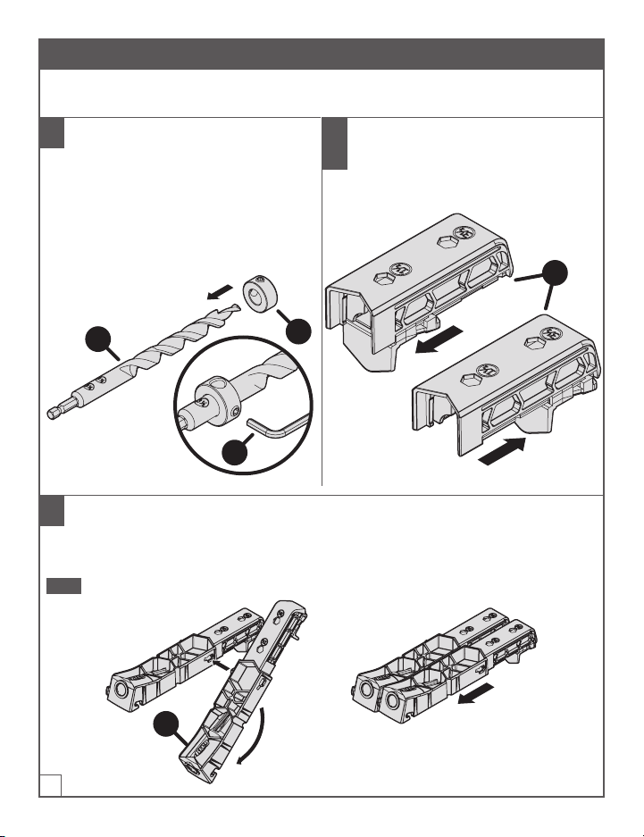
Pre-Assembly . . . . . . . . . . . . . . . . 3
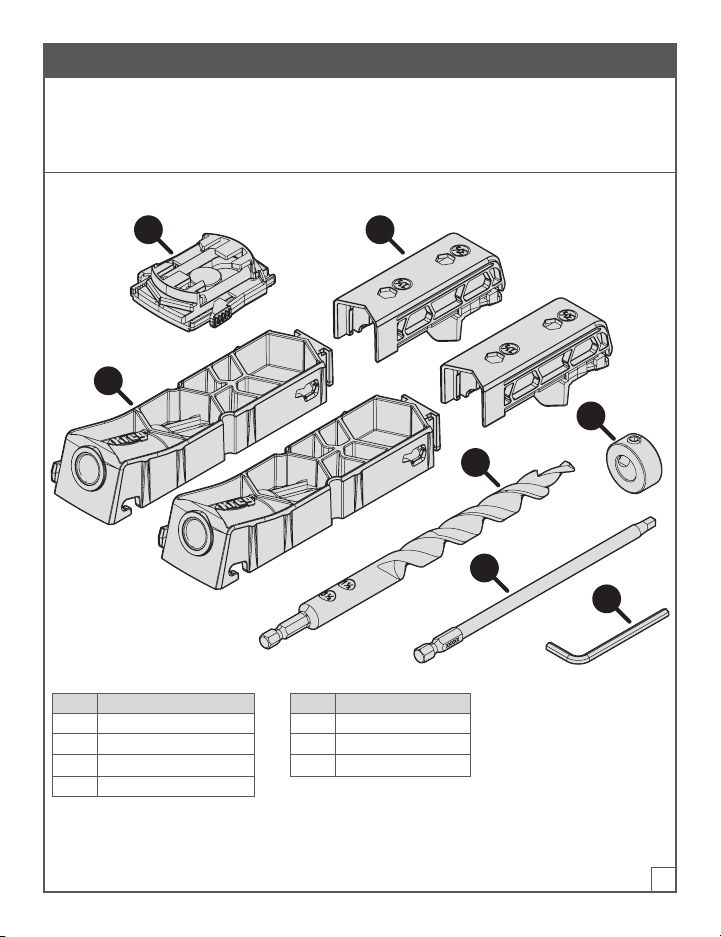
Product Description . . . . . . . . . . . 3
Assembly . . . . . . . . . . . . . . . . . . 4
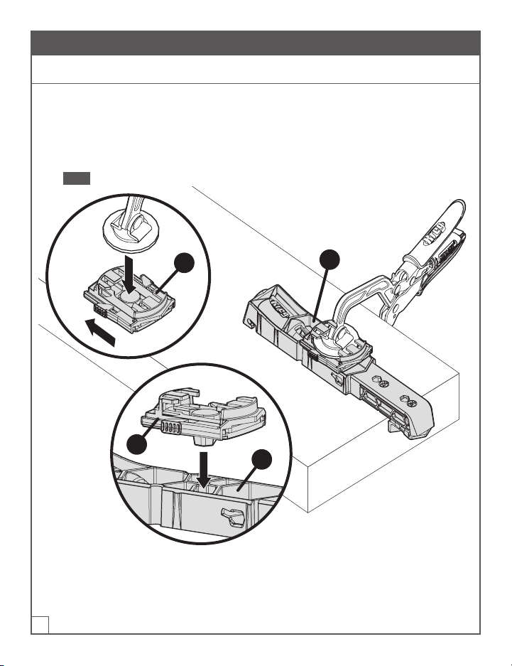
Operation . . . . . . . . . . . . . . . . . . 5
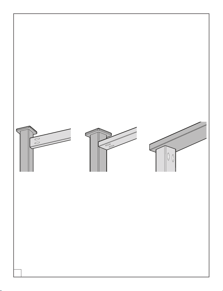
Recommended Hole Spacing . . . . . . 6
Set-Up and Screw Length Chart. . . . . 7
Tips . . . . . . . . . . . . . . . . . . . . . 8
Using the Clamp Pad Adapter . . . . . . 8
Using the Jig for Repair Applications . . 9
Using the Jig for Mitered Corners . . . . 9
Using the Jig for Railings. . . . . . . . . 10
Care and Cleaning . . . . . . . . . . . . . 11
Troubleshooting. . . . . . . . . . . . . . . 11
Accessories . . . . . . . . . . . . . . . . . 11

3
Pre-Assembly
Review this section before you begin. Ensure you have all tools on hand and compare the package
with the items listed in the Product Description section. If any item appears missing or lost, do not
use this product. Contact Technical Support or return product to place of purchase.
Product Description
F
E
C
A
G B
D
Part Description Part Description
A Drill guide E Driver bit
B Material thickness stop F Hex wrench
C Easy-set drill bit G Clamp pad adapter
D East-set stop collar

4
Assembly
1 Set the Stop Collar
a. Measure the edge of the workpiece.
b. Slide the easy-set stop collar (D) so
the desired setting on the drill bit (C)
is centered in the easy-set stop collar
window.
c. Tighten the easy-set stop collar (D) with
the hex wrench (F).
F
D
C
2 Position the Material
Thickness Stop
a. Push and slide the material thickness
stop (B) to the desired setting.
B
3 Congure the Jig
a. Insert and rotate the drill guide (A) into the other drill guide.
b. Slide the drill guide forward to join.
Note To remove, pull back and rotate the drill guide to separate.
A

5
Operation
1 Clamp the Jig and Drill the Holes
a. Align the material thickness stop (B) to the edge of the workpiece (1).
b. Clamp the jig to the piece.
Note Do not block the chip ejection hole (2).
c. Drill the pocket hole.
Tip Place pocket holes at the recommended distance from edge (X) of the workpiece.
Seenext section for recommendations.
X
1
B
2
Tip If you cannot use a clamp, secure the jig with screws in the screw recesses.

6
Recommended Hole Spacing
1" 1"
2x6 2x82x4 or 4x4
3½"
(89 mm)
5½"
(140 mm)
7¼"
(184 mm)
1¾"81½"1½"1¼" 1¼" 1¾"8
1½"1½" 1½"
2 Clamp the Joint in Place
Note Clamping secures the workpieces and gives you a better nished joint.
a. Clamp here for the face joint. b. Clamp here for the edge joint.

7
3 Drive the Screws
a. Place a screw on the driver bit (E).
b. Position the screw in the pilot hole.
c. Drive the screw until fully seated without over driving the screw.
E
E
E
E
Set-Up and Screw Length Chart For Kreg XL Screws
Material Thickness Easy-Set Stop Collar Material Thickness Stop Screw Length
1-1/2" (38 mm) 1-1/2" (38 mm) 1-1/2" (38 mm) 2-1/2" (64 mm)
3-1/2" (89 mm) 3-1/2" (89 mm) 3-1/2" (89 mm) 4" (102 mm)
Note Use of Standard size pocket hole screws will result in weaker joints.
To learn more about selecting and purchasing Kreg Screws, visit: www.kregtool.com/screws.

8
Tips
Using the Clamp Pad Adapter
The clamp pad adapter connects the jig to the clamp.
a. Position the clamp in the adapter (G) and slide closed.
b. Seat the rubber anchor of the adapter (G) in the drill guide (A) as indicated in section view
below.
Note Do not block the chip ejection hole (1).
1
G
G
A

9
Using the Jig for Repair Applications
a. Remove the material thickness stop (B).
b. Position the jig on the workpiece.
c. Clamp and drill the pocket-holes.
Note The position of the stop collar on the drill
bit does not change.
B
1½"
(38 mm)
Using the Jig for Mitered Corners
a. Remove the material thickness stop to get a screw close to the miter toe.
b. Position the drill guide on the workpiece, angled away from the miter toe.
c. Clamp the drill guide in place and drill the pocket hole.
2-1/2"
(13 mm)
(92 mm)
(92 mm)
1/2"
(64 mm)
3-5/8"
3-5/8"
2x6 2x8
2x4
Note For distances of 6" (152 mm) or more between pocket holes, drill a pocket hole
midway between the two. In general, space pocket holes about 3" (76 mm) center-to-center
along a joint. You can drill pocket holes in both parts or drill them all in one part.

10
Using the Jig for Railings
International Residential Code Guardrail Requirements: Whether manufactured or site-built,
guardrail systems must be constructed and installed to meet International Residential Code (IRC)
live-load requirements. To be compliant, guardrails must withstand a 200-lb. (91-kg) load applied
in any direction.
Compared to manufactured guardrail systems, site-built guardrails constructed of typical
dimensional lumber are not as easy to build with certainty that the live-load requirement is met.
The Code sets performance standards but does not provide proscriptive detailing for guardrail
design. It is the responsibility of the designer, builder, and local code ofcial to verify if a given
guardrail design meets the requirements.
Guardrail connections of the three styles shown here, constructed using the Pocket-Hole XL Jig,
meet the live load requirements specied in the IRC. (Testing covers only the connection of railing
members to posts, not the connection of the posts to the deck structure.) To meet requirements,
builders must execute these connections exactly as shown and use only structurally sound
materials. Materials with splits or excessive knots must not be used.
Guardrail materials and fasteners are exposed to the weather and are subject to degradation over
time. It is the homeowner’s responsibility to periodically inspect the guardrail and perform any
maintenance required to ensure continued compliance with IRC live-load requirements.
2x62x4 2x4
4x4 4x4 4x4

11
Care and Cleaning
To clean, remove any wood chips and wipe clean with a soft cloth.
Troubleshooting
Contact Technical Support or see the website for FAQs.
Accessories
2-1/2" (64 mm)
Kreg XL Screws
4" (102 mm)
Kreg XL Screws
Kreg Clamp
Kreg #3 Square Driver Bit Kreg XL Drill Bit (KPHA908) Kreg Easy-set Stop Collar
Hex Wrench

EXPLORE. BUILD. SHARE.
We’re makers just like you.
That’s why we love to see what you’re working on.
Share with the community and get inspired!
#madewithKreg
Get free plans, project resources, and more.
kregtool.com and buildsomething.com
01/2021 105772 V1

GUIDE D’UTILISATEUR
Nous sommes là pour vous aider.
Nous voulons que votre projet de construction se déroule de manière optimale.
Si vous avez des questions ou si vous avez besoin d’aide, n’hésitez pas à nous contacter.
Parlez-nous de votre expérience.
Votre opinion compte. Et nous sommes toujours à la recherche de moyens de nous améliorer.
Partagez vos commentaires an que nous puissions continuer à croître et à innover, pour vous.
www.kregtool.com/feedback
AVERTISSEMENT Chaque utilisateur doit lire et suivre les instructions et les précautions de sécurité de ce manuel.
Respectez cette consigne an d’éviter tout risque de blessures graves. Conservez le manuel pour une utilisation
ultérieure.
Gabarit pour perçage à angle XL
Le guide s’applique à l’article n°KPHJ920

14
Précautions de sécurité
AVERTISSEMENT Avant d’utiliser un outil électrique avec ce produit, veuillez lire et suivre les
instructions et les précautions de sécurité du fabricant de l’outil, en plus des précautions de
sécurité ci-dessous, an de réduire le risque de blessures graves dues à des risques comme le
feu, les chocs électriques ou les mèches de forage rotatives.
■Suivez toujours les consignes de sécurité qui se rapportent à l’utilisation de votre gabarit.
■Suivez les consignes de sécurité du fabricant de votre perceuse.
■Portez toujours un équipement de protection individuelle certié, notamment des lunettes
de sécurité ainsi qu’une protection auditive et respiratoire. Lorsque vous utilisez un outil
électrique, respectez toujours les exigences du fabricant en matière d’équipement de
protection individuelle.
■La mèche de forage est tranchante. Manipulez-la avec précaution.
■N’essayez pas de tenir le gabarit en place avec votre main pendant que vous percez un trou à
l’aide d’une perceuse. Fixez le gabarit en place à l’aide d’un serre-joint.
■Faites attention lorsque vous devenez familier avec l’outil en raison d’une utilisation fréquente.
Employez systématiquement des pratiques de travail sécuritaires. Un moment d’inattention
est sufsant pour causer des blessures graves.
AVERTISSEMENT Évitez de positionner vos mains de manière maladroite, car un glissement
soudain pourrait causer un contact avec la lame en rotation.
AVERTISSEMENT N’utilisez pas cet outil ou toute autre machine lorsque vous êtes sous
l’inuence de drogues, d’alcool ou de médicaments.
AVERTISSEMENT Ce produit peut vous exposer à des produits chimiques, notamment
l’acrylonitrile ou d’autres types dont l’État de Californie reconnait être cancérigènes et nocifs pour
la reproduction. Pour en savoir plus, visitez www.P65Warnings.ca.gov.
AVERTISSEMENT Le perçage, le sciage, le ponçage ou l’usinage des produits du bois peuvent
vous exposer à la poussière de bois, une substance reconnue par l’État de Californie comme étant
cancérigène. Évitez d’inhaler la poussière de bois ou utilisez un masque anti-poussière ou d’autres
mesures de protection personnelle. Pour en savoir plus, visitez www.P65Warnings.ca.gov.
Table des matières
Précautions de sécurité . . . . . . . . . . 14
Avant l’assemblage. . . . . . . . . . . . . 15
Description du produit . . . . . . . . . .15
Assemblage. . . . . . . . . . . . . . . . . 16
Fonctionnement . . . . . . . . . . . . . . 17
Espacements recommandés entre
les trous . . . . . . . . . . . . . . . . . 18
Tableau de réglage et longueur
des vis pour les vis Kreg XL . . . . . . .19
Astuces . . . . . . . . . . . . . . . . . . .20
Utilisation de la plaquette adaptateur
du serre-joint . . . . . . . . . . . . . . .20
Utilisation du gabarit pour des
réparations . . . . . . . . . . . . . . . .21
Utilisation du gabarit pour les coins
à onglet. . . . . . . . . . . . . . . . . . 21
Utilisation du gabarit pour des rampes . 22
Entretien et nettoyage . . . . . . . . . . . 23
Dépannage . . . . . . . . . . . . . . . . .23
Accessoires . . . . . . . . . . . . . . . . . 23

15
Avant l’assemblage
Consultez cette section avant de commencer. Assurez-vous d’avoir tous les outils et les matériaux à
portée de main et comparez ce qui se trouve dans l’emballage du produit avec les articles énumérés
dans la section Description du produit. Si un article semble manquant ou perdu, n’utilisez pas ce
produit. Contactez le soutien technique ou retournez le produit où vous l’avez acheté.
Description du produit
F
E
C
A
G B
D
Pièce Description Pièce Description
A Guide-foret E Mèche
B Arrêt de l’épaisseur de matériaux F Clé hexagonale
C Mèche à réglage facile G Plaquette adaptateur du serre-joint
D Bague d’arrêt à réglage facile

16
Assemblage
1 Réglage de la bague d’arrêt
a. Mesurez le bord de la pièce sur laquelle
vous travaillez.
b. Glissez la bague d’arrêt (D) an que le réglage
voulu sur la mèche (C) soit centré avec la
longueur souhaitée de la bague d’arrêt.
c. Serrez la bague d’arrêt (D) avec la clé
hexagonale (F).
F
D
C
2 Placement de l’arrêt de
l’épaisseur de matériaux
a. Poussez et glissez l’arrêt de l’épaisseur
de matériaux (B) jusqu’au réglage
souhaité.
B
3 Conguration du gabarit
a. Insérez et faites faire une rotation au guide-foret (A) pour qu’il s’insère dans l’autre guide-foret.
b. Glissez le guide-foret pour joindre les deux.
Remarque Pour les séparer, poussez vers l’arrière et faites faire une rotation au guide-foret.
A

17
Fonctionnement
1 Serrage du gabarit et perçage des trous
a. Alignez l’arrêt de l’épaisseur de matériaux (B) au bord de la pièce sur laquelle vous travaillez (1).
b. Serrez le gabarit sur la pièce.
Remarque Ne pas bloquer le trou d’éjection des copeaux (2).
c. Percez les trous à angle.
Astuce Placez les trous à angle à la distance recommandée à partir du bord (X) de la pièce
sur laquelle vous travaillez. Consultez la prochaine section pour des recommandations.
X
1
B
2
Astuce Si vous ne pouvez pas utiliser un serre-joint, xez le gabarit à l’aide de vis dans les
fraisures de vis.

18
Espacements recommandés entre les trous
1" 1"
2x6 2x82x4 ou 4x4
3½"
(89 mm)
5½"
(140 mm)
7¼"
(184 mm)
1¾"81½"1½"1¼" 1¼" 1¾"8
1½"1½" 1½"
2 Serrez le joint en place
Remarque Serrer le joint xe les pièces de travail et entraîne une meilleure nition de joint.
a. Serrez à cet endroit pour un joint face à face.
b. Serrez à cet endroit pour un joint
longitudinal.

19
3 Vissage des vis
a. Placez une vis sur la mèche (E).
b. Placez la vis dans l’avant-trou.
c. Vissez la vis jusqu’à ce qu’elle soit bien en place sans la visser trop profondément.
E
E
E
E
Tableau de réglage et longueur des vis pour les vis Kreg XL
Épaisseur du
matériau
Bague d’arrêt à réglage
facile
Arrêt de l’épaisseur de
matériaux
Longueur de la vis
1 1/2po (38mm) 1 1/2po (38mm) 1 1/2po (38mm) 2 1/2po (64mm)
3 1/2po (89mm) 3 1/2po (89mm) 3 1/2po (89mm) 4po (102mm)
Remarque L’utilisation de vis de taille standard pour perçage à angle fera en sorte que le joint
sera plus faible.
Pour en apprendre davantage sur le choix et l’achat de vis Kreg, visitez: www.kregtool.com/screws.

20
Astuces
Utilisation de la plaquette adaptateur du serre-joint
La plaquette adaptateur du serre-joint connecte le gabarit au serre-joint.
a. Placez le serre-joint dans l’adaptateur (G) et faites glisser jusqu’à ce qu’il soit fermé.
b. Placez la cheville de caoutchouc de l’adaptateur (G) dans le guide-foret (A) comme illustré
ci-dessous.
Remarque Ne pas bloquer le trou d’éjection des copeaux (1).
1
G
G
A
Table of contents
Languages:
Other Kreg Power Tools manuals