2
Ausgabe: November 2020
Zeichnungs-Nr: 027191-21
Technische Änderungen im Sinne der Pro-
duktverbesserung vorbehalten.
Urheberrecht und Hersteller :
Firma Kroll GmbH
Edition: November 2020
Drawing number: 027191-21
Technical hanges in the sense of product
improvement reserved
Privilege of the producer:
Firma Kroll GmbH
Edition Novembre 2020
No. du dessin: 027191-21
conformément aux circonsstance
Toute modication réservée dans le but de
l’amélioration du produit
Droit du fabricant:
Sté Kroll GmbH
Am Aufstellungsort gelten die allgemeinen
bau- und feuerpolizeilichen Vorschriften, so-
wie die UVV (Unfallverhütungsvorschriften)
Elektroheizer nur unter Beachtung der
Betriebsanleitung in Betrieb
nehmen !
Gerät vor Trennung vom Stromnetz
über Lüftungsbetrieb abkühlen
lassenerät v
or Trennung vom Stromnetz
Transportschäden
Transportschäden müssen auf dem Spediti-
onsannahmeschein vermerkt und vom Fahrer
quittiert werden. Technische Störungen müs-
sen unverzüglich Ihrem Händler angezeigt
werden. Gerät erst nach Instandsetzung in
Betrieb nehmen.
Folgeschäden durch Betriebsausfall des
Gerätes sind von der Haftung ausge-
schlossen.
Einsatzbereich
Bausektor - Trocknen und Beheizen von Bau-
stellen, Werkshallen, Aufstellungsräumen und
Garagen.
Agrarsektor - Trocknen und Beheizen von
Ställen und Gewächshäusern
Wohnbereich - schnelles und gezieltes Heizen
für alle Räume.
Vorschriften Regulations Directives
Any cases of consequential damage due to
the failure of the device during operation
will be excluded from liability.The general
regulations as issued by the Board of Works
in your country and the accident prevention
regulations, are to be followed during instal-
lation
Put into operation the electrical hea-
ter only by following the instruction
manual !
Before cutting the heater from elec-
trical supply, ensure cooling down by
working on „ventilation“
Damage during transport
Transport damages must be noted on the for-
warders receipt and signed by the driver. Your
dealer must be notied of any technical dama-
ge before the appleance is assembled and set
into operation. The heater is only be started
up after competent repair.
Any cases of consequential damage due to
the failure of the device during operation
will be excluded from liability.
Possibilites uf use
Construction eld - drying and heating con-
strutions sites, work shops, exhibition halls
and garages.
Agricultural eld - drying and heating stables
and greenhouses.
Living area - rapid and precise heat for all
rooms.
Sur le lieu du montage, les directives géné-
rales des services d’urbanisme et de lutte
contre l’incendie sont valables. Des dégâts
à l‘appareil de conséquence résultant d’une
interruption des générateurs d’air chaud sont
exclusde la responsabilité.
Ne mettre en marche le chauffage
éléctrique qu’apres lecture de la noti-
ve technique !
Avant couper l’appareil de
l’alimentation électrique, assurez son
refroidissement en fonction
„ventilation“
Dommages au cours du transport
Les dommages survenus au cours du trans-
port doivent être notés sur le bon reception et
signé par le conducteur. Des dommages tech-
niques doivent être signalés sous 48 heures
avant le montage et la mise en service auprès
de votre revendeur. Ne mettre l’appareil en
service qu’après la remise en état.
Des dégâts à l‘appareil de conséquence
résultant d’une interruption des généra-
teurs d’air chaud sont exclusde la respon-
sabilité.
Possibilities d’utilisation
Construction - les chantiers, les atéliers, les
halles d’exposition et les garages.
Agriculture - secher et chauffer les ètables et
les serres.
Habitations - Chauffage rapide et précis pour
tous les locaux.
Vorschriften
Transportschäden
Einsatzbereich.............................................2
Inbetriebnahme............................................3
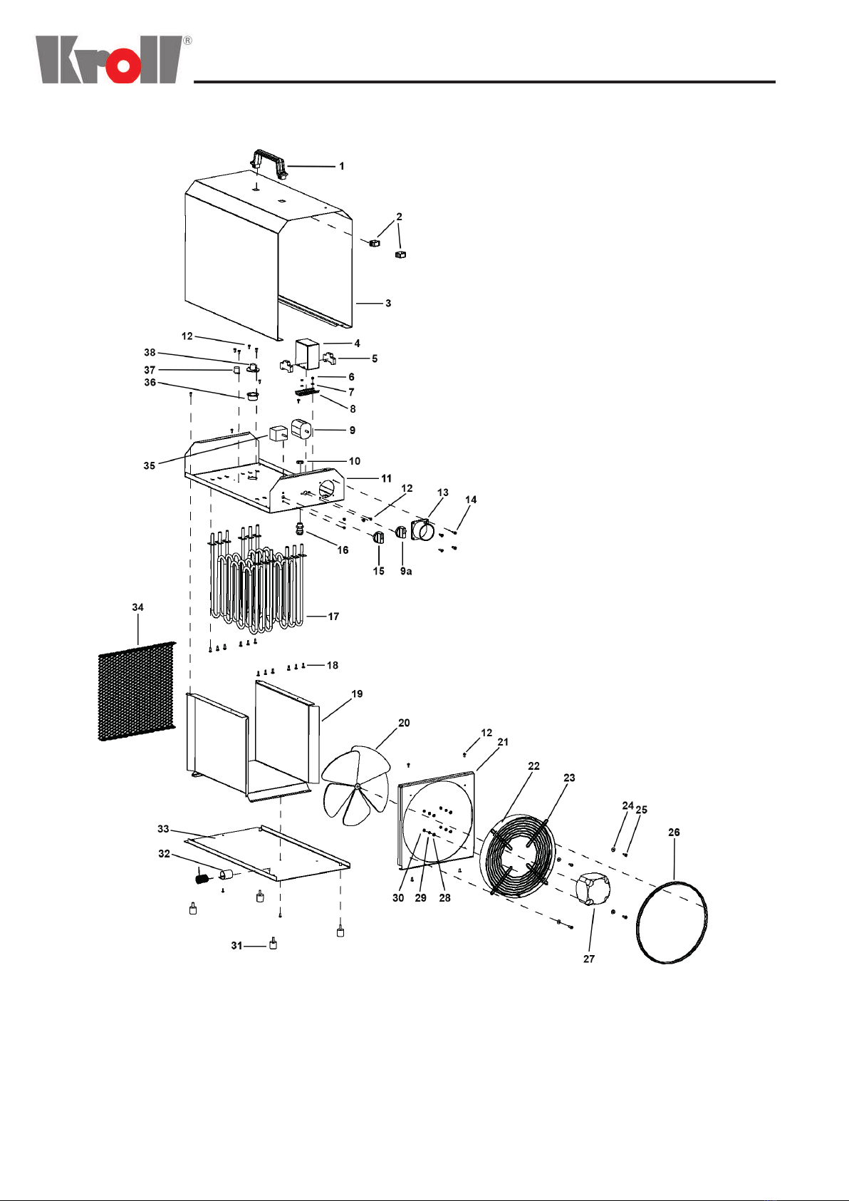
Einzelteile
E8 .....................................................4 - 5
E12 ......................................................6 - 7
E18 ......................................................8 - 9
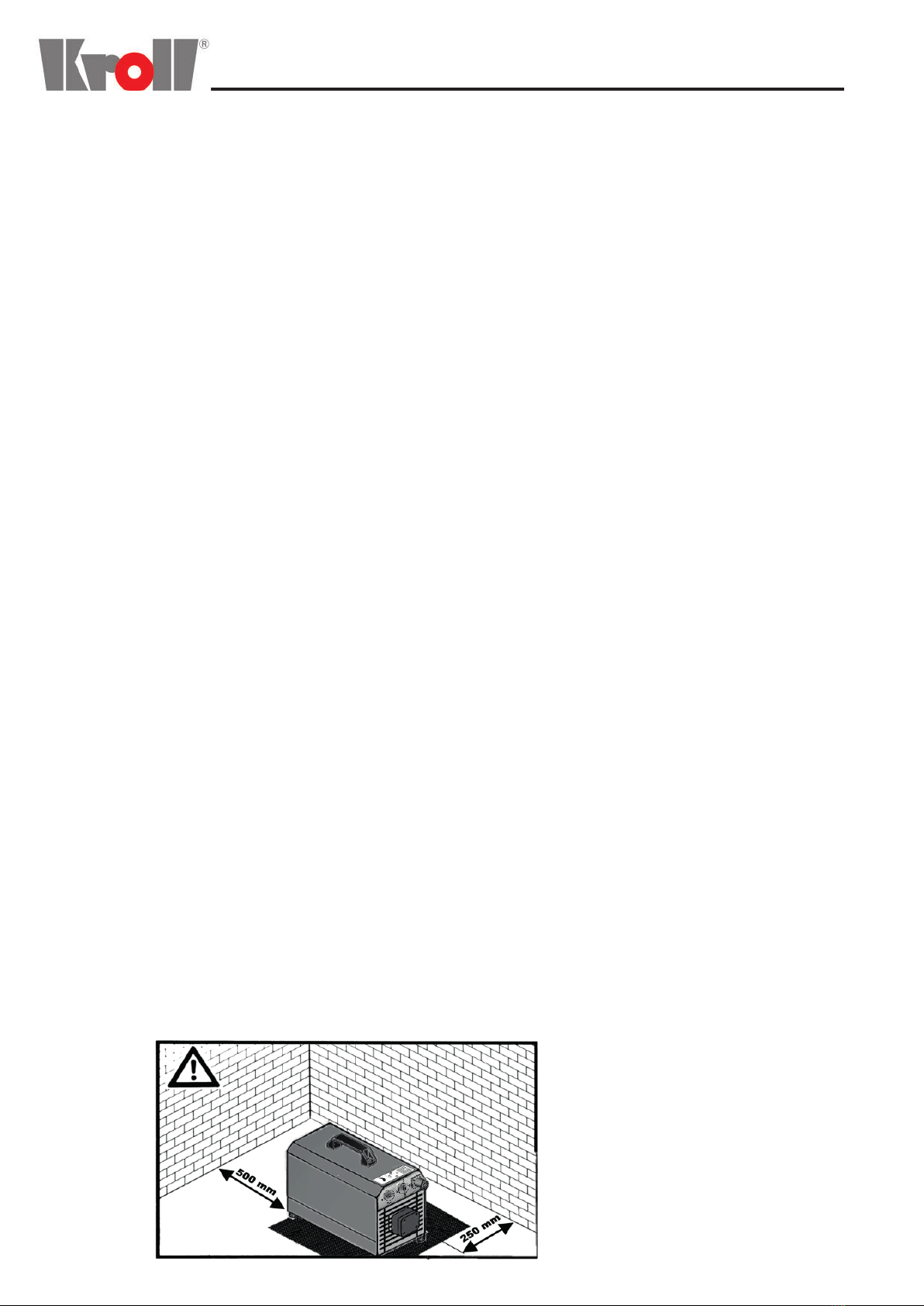
Aufstellungsvorschriften
Vorsichtsmaßnahmen beim Betreiben
Wartung und Reparaturen .........................10
Schaltplan E8/E12......................................11
Schaltplan E18...........................................12
Technische Daten......................................13
Konformitätserklärung ...............................14
Regulations
Damage during transport
Possibilites of use........................................2
Setting into operation...................................3
Component parts
E8 .....................................................4 - 5
E12 ......................................................6 - 7
E18 ......................................................8 - 9
Installation regulations
Precautions
Servicing and repair work..........................10
Circuit diagram E8/E12...............................11
Circuit diagram E18....................................12
Technical data............................................13
EC-Conformity...........................................14
Directives
Dommages au cours du transport
Possibilities d’utilisation...............................2
Mise en marche...........................................3
Nomenclature
E8 .....................................................4 - 5
E12 ......................................................6 - 7
E18 ......................................................8 - 9
Directives mise en place
Précautions en mettant en marche
Entretien et reparations .............................10
Schema électrique E8/E12.........................11
Schema électrique E8/E12.........................12
Caractéristiques techniques ......................13
Déclaration de conformité CE....................14
Inhaltsverzeichnis / Table of contents / Sommaire