Kr. F.
We are very appreciated for your adopting CM Series of Portable Lifter. Our company is
the team insisted in High Quality and Excellent Technology to manufacture all types of
professional equipment to help the customers to create high profits and high quality products.
CM Series Portable Lifts are the professional equipments to install, position and lifting:
.Electric Curly Doors. .Iron Racks
.Pipe Equipment of Freezing .Air Coolers,
.Air Conditioners .Indoor Machinery
.Water Freezers .Large Screen
.Single Gun
Water
and Electricity Equipment
.Double-Gun or Triple-Gun Projectors .Overhead TV equipment
.Hiqf Up Cameras .Lighting
.Housewares
1. Telescoping Mast: constructed from heat treated, extruded aluminum, compact, safety,
strength and reliability.
2. Set-Up without tools: The LEGS can be release or fold out in seconds.
3. Telescoping legs: Versatile and infinitely adjustable, available use in uneven ground, for
example, stairway.
4. Electric remote control with variable speed switch, it can be used in soft start.
5. Emergency Stop Button: press the button for stop raising or lowering immediately.
6. Automatic Overload Breaker is equipped to prevent of over weight loading.
7. Level: equip with the Level inside the cylinder to ensure the proper set up.
8. CM·520H1 equipped with
swivel/lock
with break caster, make it easy to move to next work
position.
9. Platform: Special design for install the window type of Air-conditioner. Detaches from the mast.
10. The compact design make it easily for one person to carry it from job to job.
11. Special design can let you working close to the wall.
a
--
-
K.S,F. •
.-.11::»
1.
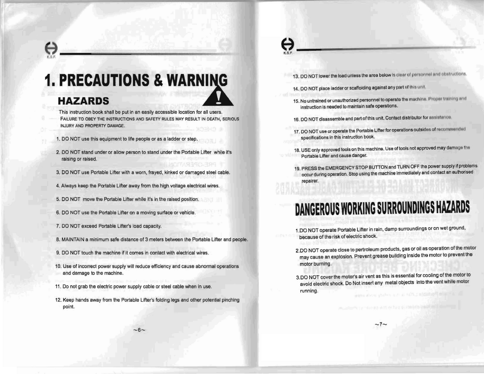
PRECAUTIONS
& WARNING----------
2.
TRANSPORTING
THE PORTABLE L1FTEI{·
3. STORAGE-------------------------------------------- --
4. CHECK --------------------------------------------------------
I ,
I)
1u
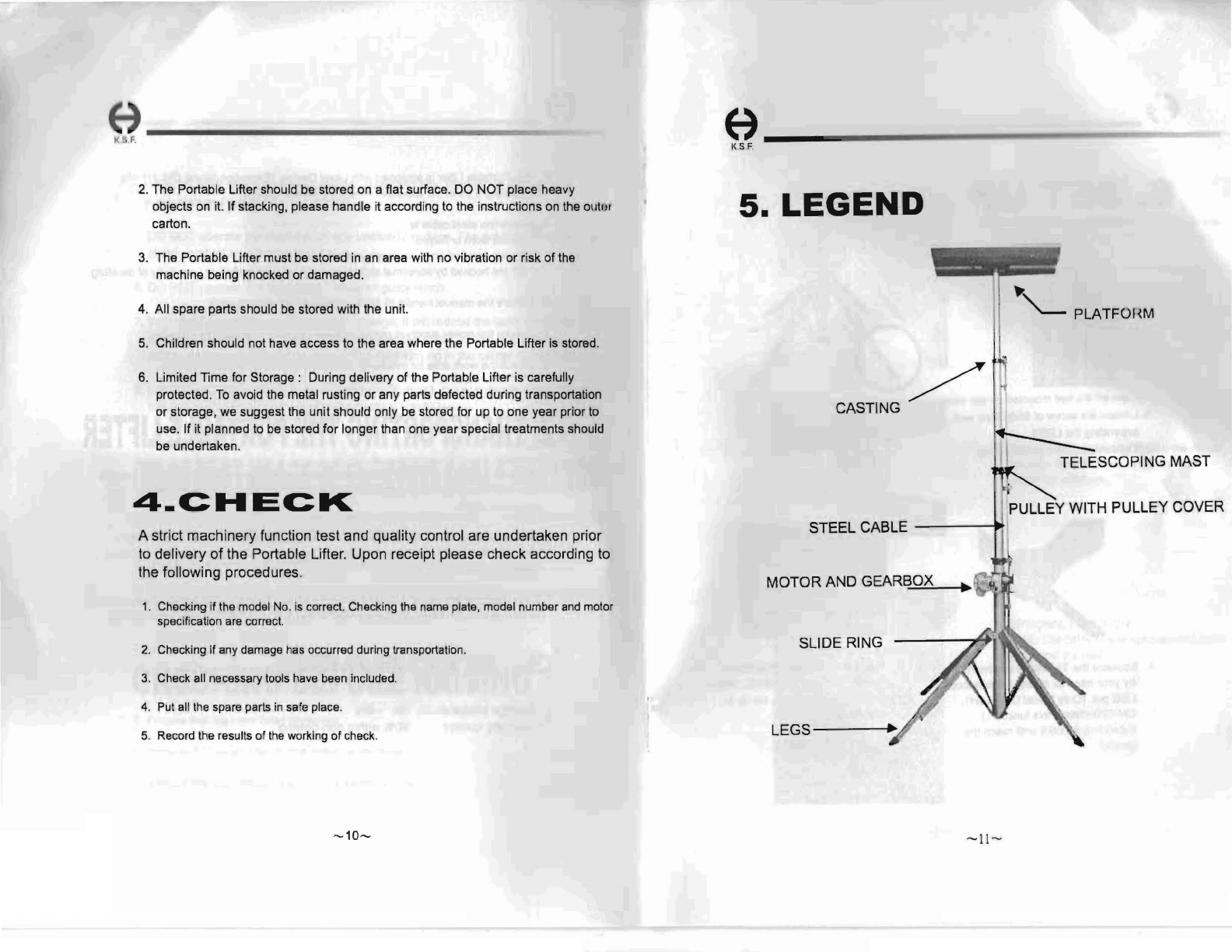
5. LEGEND ------------------------------------------------------------ - _• l '
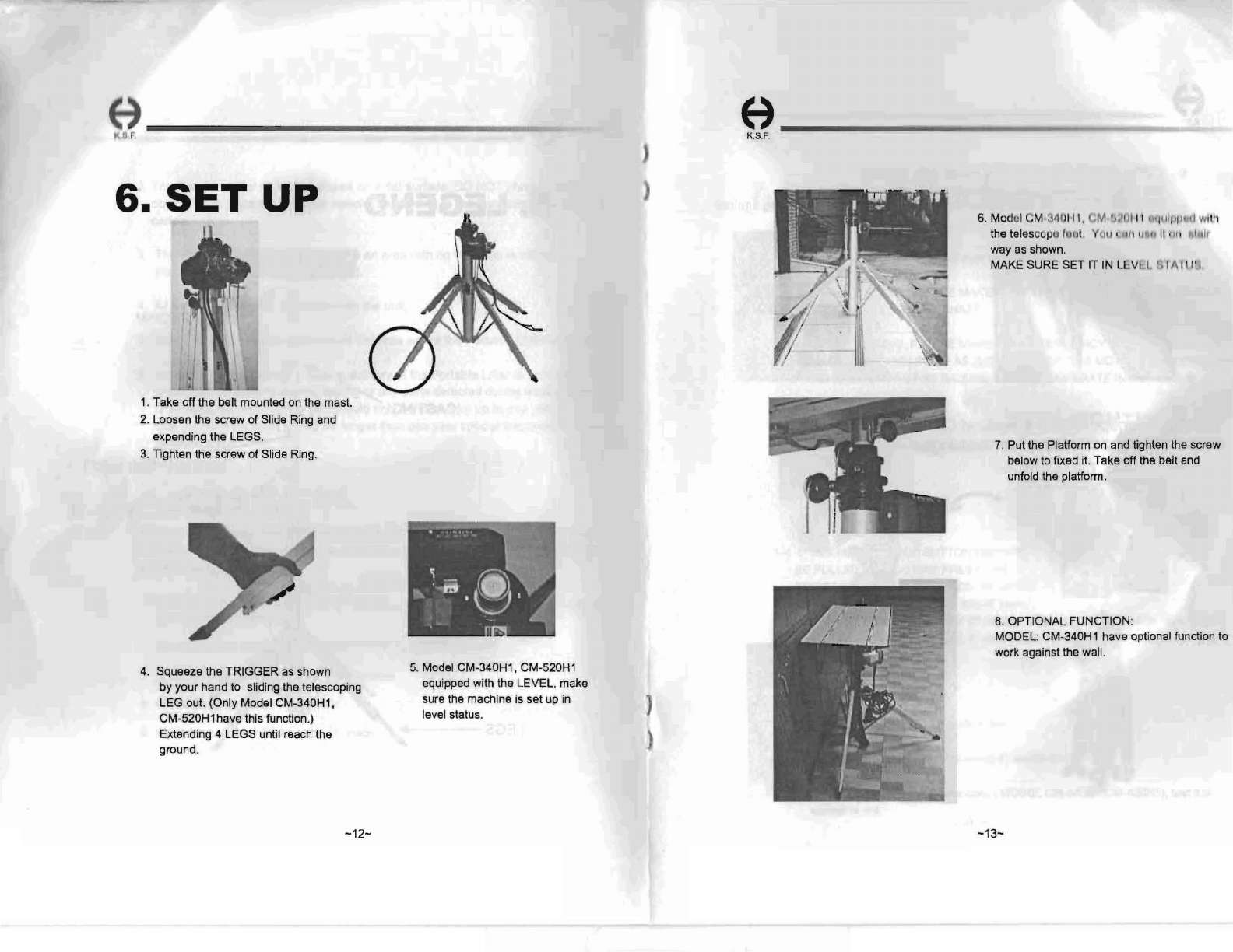
6. SET UP ---------------------------------------------------------------------- ,
7. PRE-OPERATION INSPECTION----------------------------------------- 1
~
8. RAISING AND LOWERING ------------------------------------------------ 16
9.
EMERGENCY
STOP BUTTON, MANUALLY ------------------------- 18
1O. DISASSEMBLY -------------------------------
---------------------
--------- 19
11.0 RDINARY EXAMINATION ------------------------------------------------ 20
12. APPENDIX
-----------
21
13. SPARE PART DRAWINGS ------------
-----------------
------
-------
22
~5~
~4~