ASSEMBLY INSTRUCTIONS4
TRACTOR PREPARATION
1. Remove the mid mount mower from the tractor if
equipped.
2. Locate the tractor on a firm level surface.
Lower the implement to the ground, set the parking
brake and stop the engine.
3. Set front tread as follows.
ASetting tread wider than recommended may cause
premature failure of front axle components due to
excessive stress.
4. For better stability, set the rear tread as follows
depending on the requirements of the work being
done.
BEFORE ASSEMBLY
ABefore assembling the hardware (bolts, adapters,
hoses, etc.), ensure all contaminates (grease, grit,
dust, etc.) are removed from the threads and all mating
surfaces (Tractor, Main Frames, etc.). If oil or
contamination has adhered, clean off thoroughly
before assembling (by using contact cleaner,
scrapers, etc.). If oil or contamination remains on the
threads, it may lead to damaged threads and the
loosing of hardware and/or parts.
AFor the tightening torque, see the tables at the end of
this manual. If the torque values are specified in the
text, follow that specification.
ADo not tighten any bolts firmly until most components
are attached to the tractor.
ABefore tightening all mounting hardware, start the
engine and apply down pressure with the bucket until
the loader takes the tractor weight off the front wheels
without lifting the front wheels off of the ground. Make
sure that the mounting pins can be rotated easily (Pin
on mount), or the Swift-Tach hooks can be unlocked
easily (Swift-Tach mount). Torque all bolts and nuts in
this position.
ADuring assembly of all hydraulic parts make sure parts
remain clean of contamination. If contamination
occurs it could affect the performance of the hydraulic
system.
AWhen using the tapered adapters, wrap the seal tape
around the thread part 2 or 3 times. At this time,
ensure all contaminates are removed from the
threads.
ATo avoid damage to hoses, adjust all connections to
route hoses away from sharp edges and do not twist
hoses.
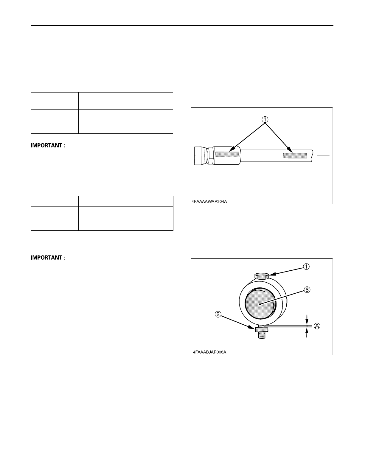
AThe part number of the hose is marked on the hose
fitting, or located on the hose.
AWhen fixing the pin with the bolt and nut, do not tighten
the nut completely as shown. The clearance between
the boss and the nut should be 2 to 3 mm (0.08 to 0.12
in.).
AWhen applying label:
(1) Clean off all contaminates (dust, oil, grease, etc.)
from surface before applying label.
(2) Do not use the cotton work gloves or touch the
label adhesive surface with your hand.
AAssemble on a hard surface, preferably concrete.
Front Tread
2WD 4WD
L2501
L3301
L3901
Front axle is not
adjustable.
Front axle is not
adjustable.
Rear Tread
L2501
L3301
L3901
1115 mm (43.9 in.) or more
(1) Part number
(Marked on either position)
(1) Bolt
(2) Nut
(3) Pin
(A) 2 to 3 mm (0.08 to 0.12 in.)