Kubota KB-GS-20S User manual

[_]
-
c
-
g
•
-
•
KB-GS20-S
PT METEC SEMARANG
KB-GS30-S
MANUAL SERVICE
www.kubota-ptms.co.id
KB-GS24-S
TPK Vending Corporation Co., Ltd.

- i -
INTRODUCTION
Thank you for buying Kubota Vending Machine. This manual describes the guide, work
instruction, service, installation and list of parts. Read carefully and follow the instruction so as to
understand the features and functions of installation and use of Vending Machine.
This Vending Machine is used to sell can- and PET bottle-packed drinks by using Malaysian
All of selling system, pricing and machine features can be controlled using the control
system. Identification of machine unit is adjusted to the model and serial number on the Plate
Brand attached on the front lower part of the door. Keep the serial number, in case of any issues
or questions of the Vending Machine, it must refer to the model and serial number of the Vending
Machine.
After reading this Service Manual, keep it safely and refer to it if you do not understand
something. In case of questions of installation, operation, assembly and replacement of parts,
please contact local dealer or service agent.
Thank you.
paper money and the coins.
TPK Vending Corporation Co., Ltd.

- ii -
CONTENTS
CONTENTS ...............................................................................................................................................
ii
INTRODUCTION
....................................................................................................................................... i
1.
SAFETY CHAPTER ...........................................................................................................................
1
2.1
UNIT
SPE
CIFICATIONS
..........................................................................................................
3
2.2 WIRING DIAGRAM
.................................................................................................................. 12
3. INSTA
L
LA
T
I
ON .................................................................................................................................. 21
3.2
INSTALLATION
SPE
CIFICATIONS
.........................................................................................
2
4
3.3
ABOUT TRANSPORTATION ...................................................................................................
2
7
3.4
INSTALLATION GROUNDING
................................................................................................
2
7
4.
LOADING PRODUCT ........................................................................................................................ 28
4.1
TYPE
SPE
CIFICATION
AND
LOADING CAPACITY ...............................................................
2
8
4.2
HOW TO SET UP
THE
STOCKER
......................................................................................... 31
5. CONTROLLER
..................................................................................................................................
3
2
5.1 KEYBOARD
DESCRIPTIONS AND FUNCTION
..................................................................... 32
5.2
SPECIFIED KEY FUNCTION LIST
.......................................................................................... 33
5.3
MODE KEY FUNCTION LIST ..................................................................................................
3
4
5.4 S
PESIFIED
KEY OPERATIONS .............................................................................................. 35
Single Test Vend ................................................................................................................... 35
Coin
Test vend
(Option) ........................................................................................................... 35
Consecutive Test Vend (Select column using selection button) ..............................................
3
5
Consecutive Test Vend
(
Select column using remote keyboard
)
............................................ 35
Rapid Consecutive Test Vend
(
Select column using selection button
)
....................................
3
5
Rapid
Consecutive Test Vend
(
Select column using k
eyboard)
..............................................
3
6
Sequential Test Vend
...............................................................................................................
3
6
View/Clear
Total
Vend Count and Count per Column
..............................................................
3
6
View/Clear Group Vend Count
.................................................................................................
3
6
View
Lifetime
Vend Count
........................................................................................................
3
6
Set
/
View
Suspend
Vending Hours/C
ol
u
m
n..............................................................................
3
6
Set
/
View
Suspend
Vending Mode ............................................................................................
3
7
Set/View Alternate Sales
..........................................................................................................
3
7
Set/View Space to Sales .......................................................................................................... 37
Set/View Pricing Product
.......................................................................................................... 37
View/Clear Occuring Error Code
.............................................................................................. 37
2. SPE
CIFICATIONS
.............................................................................................................................
3
3.1 SPACE INSTAL
L
A
T
I
ON
...........................................................................................................21
TPK Vending Corporation Co., Ltd.

- iii -
5.5
MODE KEY OPERATIONS .......................................................................................................
3
8
Group Count Setting
(1 – 02)
.................................................................................................
3
8
Free Column Setting
(1 – 15)
.................................................................................................
3
8
School Timer Hours Setting
(2 – 01)
...................................................................................... 39
Select School Timer Operation Patern
(2-02)
.........................................................................
3
9
Lighting Saving Hours
(2 – 03)
............................................................................................... 40
Refrigerator Unit Power Saving Hours
(2 – 04)
...................................................................... 40
Set Clock (2 – 05) ................................................................................................................... 40
Set Month and Date
(2 – 06)
.................................................................................................. 40
Set Year
(2 – 07)
.................................................................................................................... 41
Lighting Management Mode Setting
(3 – 01)
......................................................................... 41
Daylight Sensor Sensitivity Setting
(3 – 02)
........................................................................ 41
Set
Counter per Group (3 – 03)
.............................................................................................. 41
Selection Button Illumination Pattern
(3 – 30)
........................................................................ 42
Selection Button Illumination Hours
(3 – 31)
..........................................................................
4
2
5.6 RAM CLEAR・
ADJUST MACHINE CODE ..............................................................................
4
3
5.7
LIST OF ERROR CODE ...........................................................................................................
4
4
6.
ERROR C
ODE
S
AND
CORECTIVE ACTIONS .................................................................................
4
5
7.
HOW TO REMOVE
UNIT
...................................................................................................................
4
8
7.1
TO REMOVE
RACK UNIT
........................................................................................................
4
8
7.2
TO REMOVE
VEND MECH
...................................................................................................... 51
7.3
TO REMOVE
REFRIGERATION UNIT
.....................................................................................
5
2
7.4
TO REMOVE
POWER RELAY UNIT
........................................................................................
5
6
8.
ERROR
DIAGNOS
E...........................................................................................................................
5
7
8.1
SALES CONDITION STAND BY CONFIRMATION ..................................................................
5
7
8.2 DIAGNOS
E
COOLER FUNCTION ............................................................................................
5
9
8.3 DIAGNOSA
HEATER FUNCTION .............................................................................................
5
9
8.4 DIAGNOS
E POINT ................................................................................................................... 60
9.
CLEANING AND MAINTENANCE ...................................................................................................... 61
10.
PARTS LIST AND FIGURES ..............................................................................................................
6
2
10.1 CASE PARTS
............................................................................................................................
6
2
10.2 CASE・RACK PARTS
.............................................................................................................
6
4
10.3 INNER DOOR・MONEY INSERT
........................................................................................... 70
10.4 DOOR・DELIVERY PORT PARTS
.......................................................................................... 74
10.5 DISPLAY PANEL PARTS
..........................................................................................................
7
6
10.6 REFRIGERATION UNIT PARTS
...............................................................................................
7
8
10.7 WIRING PARTS
......................................................................................................................... 80
10.8 LABEL・ACCESSORIES PARTS
............................................................................................
8
3
11. INFORMA
T
I
ON ...................................................................................................................................
8
9
12. REVI
S
I
ON ........................................................................................................................................... 90
TPK Vending Corporation Co., Ltd.

~
....
•
""
~
r
•
CAUTION
WARNING
CAUTION
WARNING
Meaning of displays and symbols
Meaning of displays and symbols used in this manual are as follows:
Incorrect handling may cause serious
injury or death to user.
Incorrect handling may cause injury
to user, or cause physical damage.
㶎㩷Physical damage means any damage to facilities
near the machine.
!Examples of symbols
Indicating caution (danger, warning). An icon inside or word behind the symbol shows
caution. Left mark indicates caution of electric shock.
Indicating restriction. An icon inside or word behind the symbol shows restriction.
Left mark indicates no touching restriction.
Indicating constraints. An icon inside or word behind the symbol shows constraint.
Left mark indicates unplug the power.
Important contents on safety. Please read before using and follow the instructions.
A specialist contractor or installer should
do installation and re㵥installation.
!
Poor installation may cause fall accident,
electricity shock, fires.
!
Always plug into grounded three pole socket.
!
Do not connect ground to gas pipes, water
pipes, lightning rods, phone wires.
!
Grounding resistance must be less than 4".
!
Incomplete grounding may cause electricity
shock.
Safety Tips
1 SAFETY CHAPTER
- 1 -
TPK Vending Corporation Co., Ltd.

Important contents on safety. Read it carefully before using.
WARNING
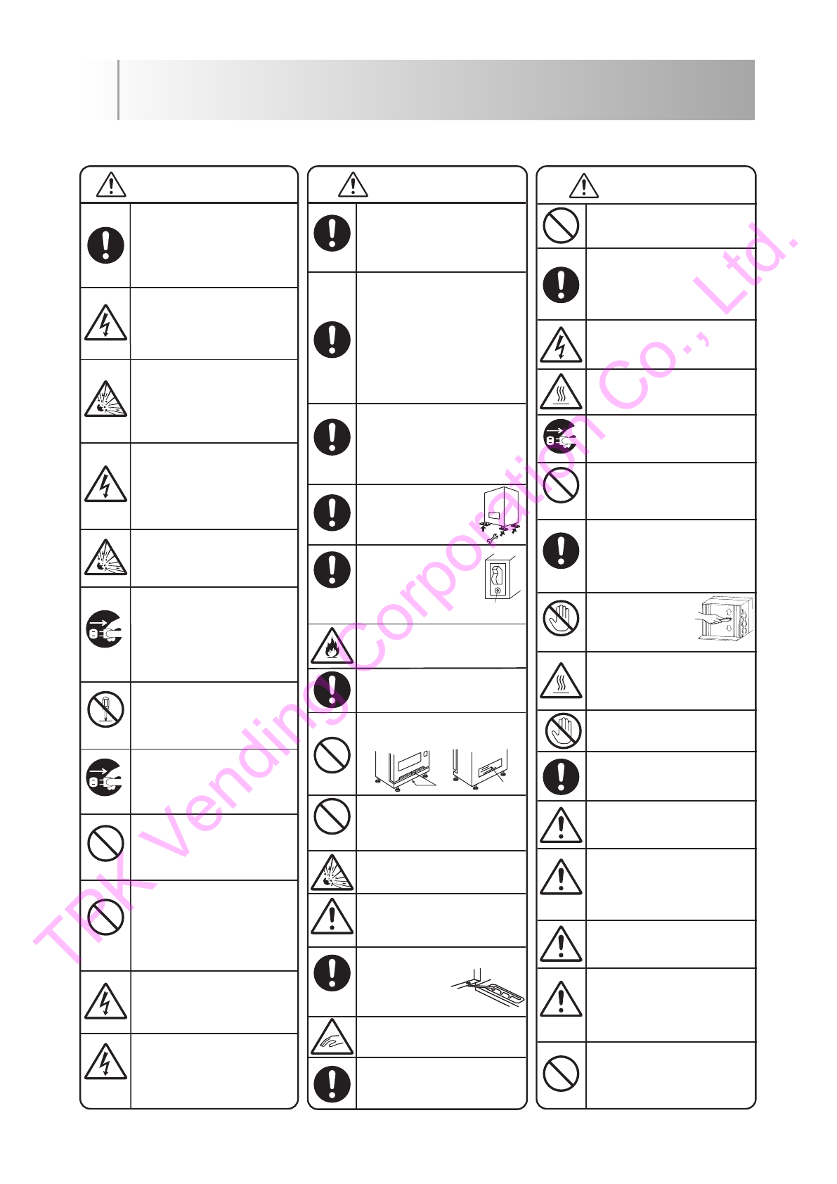
Use special outlet for power, be sure
to insert the plug until it reaches the
base.Use specified power capacity.
!Extension cords and octopus
wiring may cause fires.
When leakage breaker is working, do
not switch ON, request for inspection.
!Forced Switch ON may cause
electric shock or fires.
Do not install nor use flammable
substance (e.g. thinner) or gas or
highly volatile material near
the machine.
!May cause fire or explosion.
Soda drink cannot be warmed.
!Container may burst and it is very
dangerous.
In abnormal conditions, immediately
unplug the power, and contact
professional repairers or technicians.
!Continue operating under abnormal
conditions, may cause electric
shock or fire.
Do not overhaul or repair, unless by
professional.
!May cause injury, electric shock,
or fire.
When the machine is submerged,
immediately unplug power.
!May cause fire or electric shock.
Do not use water washed electrical
components and wiring anymore.
!May cause fire or electric shock.
Store vending machine in a warehouse
and lock the vending machine and
the warehouse.
!May be used for children
playground and cause fall
accident.
Do not operate electric plug and
switch using wet hands.
!May cause electric shock.
During product replenishment on
rainy or snowy days, beware not to
make internal electrical components
wet.
!May cause electric shock.
Do not modify, pull, place heavy
object on top, or damage the
power code.
!May cause fire or electric shock.
Clean and renew the warning
indication in order to be able read it
correctly.
!May cause accident if it can not be
read correctly.
When installing on the following
locations, discuss first with the fire
department.
!Get in the way of traffic or disaster
prevention
!
Around the fire extinguishing facilities
!
Area that handle flammable materials
or gas
!Gasoline station
!Passage and facilities for evacuation
When installing on the following locations,
discuss first with the supplier.
!Area exposed to briny air & corrosive
gases
!Area with great amount of shakes
and vibrations.
Regularly inspect installation
surface and its brackets.
!Incomplete installation
may cause fall accident.
Check operation of leakage
breaker more than
1x/month by pressing
the test button.
!Abnormal operation may
cause electric shock
Periodically clean the power plug, and
insert plug until it reaches the base.
!
Dust on the poor merge may cause fire.
Use only specified voltage and frequency.
!Operating under unspecified voltage
and frequency may cause accident.
Don’t block air inlets and outlets.
!
Poor ventilation may cause
accident.
Keep heating device away from the
power cord.
!May cause fire, electric shock if the
cord melts.
Use products without contents for display.
!
May explode as temperature increase,
and cause injury.
Be careful of passers or vehicles when
opening the door.
!May cause accident by passers or
vehicles.
When the opening the door,
fix it not to close.
!May cause injury
if the door suddenly
close due to wind.
When opening and closing the door,
be careful of fingers.
Test button
Load only the given products.
!Loading unspecified product may
cause accident.
CAUTION
This machine is designed for domestic
use only. Do not use in foreign country.
!Due to difference in voltage, may
cause fire, smoke, or burnout.
When disposing the machine, delete
device features for notes, cards,
coins identification.
!May cause criminal fraud and
forgery.
Do not look straight in to the LED
lighting for long time.
!May have bad effect on your eyes.
Do not load leaked or deformed products.
!May cause accident.
Use protective gears (gloves, long
sleeves) when touching column or
detaching components, except for
product packing or column setting.
!May cause injury.
㩷
Turn power off when replacing
fluorescent tubes(LED lamp).
!May cause electric shock.
Replace fluorescent tubes (LED lamp)
after cooling down.
!May cause burning.
Turn power off during cleaning and
inspection.
!
May cause electric shock and injuries.
During maintenance, do not apply water
directly by water hose or bucket.
!
May cause electric shock or
machine failure.
While cleaning the condenser, when
opening the cover, do not touch
the edges, use the holes on the left
and right side.
!May cause injury.
While cleaning the
condenser, do not touch
the fins.
!May cause injury.
Do not touch the delivery chute, when
compartment is heated.Turn off power,
wait untill it cools down.
!May cause burning.
Don’t touch moving part.
!May cause injury.
Destroy the key when disposing the
machine.
!May cause abuse.
When disposing the machine, Fluorescent
tubes, Freon, nickel-cadmium batteries
must be disposed of in accordance with
the prescribed method.
!
May cause environmental destruction
While cleaning the front panel and
display, beware of the projections.
!May cause injury.
CAUTION
1 SAFETY CHAPTER
- 2 -
Inlet outlet
TPK Vending Corporation Co., Ltd.

=
,
-
-
~
KB-GS20-S
- 3 -
Coin mech
e-money
Bill validator
Power
Cooling Unit
Refrigerator/volume
KB-GS30-S
1846
1160
794 (45+749)
50
290 kg
6 rows serpentine rack
-
R134a/220 g
LED x 4 pcs
1846
1160
839 (90+749)
50
285 kg
6 rows serpentine rack
-
R134a/220 g
LED x 3 pcs
KB-GS20-S
1846
999
712 (45+667)
50
235 kg
5 rows serpentine rack
-
AC-3C1101E
R134a/220 g
LED x 4 pcs
45 667
1846
999
External
!
"
#
$
%
!
&
$
'
Height
(mm)
Width
(mm)
Depth
(mm)
Required rear clearance
(mm)
Empty Weight
(Kg)
Selection
Vending Mechanic
20
Selection
(20 Selection
Button
) 30
Selection
(30 Selection
Button
)24
Selection
(24 Selection
Button
)
(
S
elenoid
Operated
)(
S
elenoid
Operated
)(
S
elenoid
Operated
)
Lamp
2-1 UNIT SPECIFICATIONS
2 SPECIFICATIONS
KB-GS24-S
Single phase AC2
3
0V 50Hz Single phase AC2
3
0V 50Hz Single phase AC2
30
V 50Hz
AC-3C110
2
E
AC-3C110
2
E
Factory default not equipped
Factory default not equipped Factory default not equipped
Factory default not equipped
TPK Vending Corporation Co., Ltd.

-
-
=
I
•
DD
•
-
g
D
- 4 -
KB-GS30-S
74945
1846
1160
1846
749
90
1160
1846
2-1 UNIT SPECIFICATIONS
2 SPECIFICATIONS
KB-GS24-S
TPK Vending Corporation Co., Ltd.

-
•
D
Ill
-
- 5 -
Levelling screw
Digital indicator
Bill insert
Door handle
Coin return
Dummy holder
Selection button
※Price indication
indication
Delivery port
Coin insert (option)
Return lever (option)
Coin insert (option)
Return lever (option)
KB-GS20-S
Levelling screw
Digital indicator
Bill insert
Door handle
Coin return
Dummy holder
Selection button
※Price indication
indication
Delivery port
KB-GS30-S
2-1 UNIT SPECIFICATIONS
※HOT/COLD
※HOT/COLD
2 SPECIFICATIONS
TPK Vending Corporation Co., Ltd.

DD
D
-
-
•
※Price
- 6 -
Levelling screw
Digital indicator
Bill insert
Coin insert (option)
Return lever (option)
Door handle
Coin return
Dummy holder
Selection button
※Price indication
indication
Delivery port
2-1 UNIT SPECIFICATIONS
※HOT/COLD
・HOT/COLD indication
2 SPECIFICATIONS
KB-GS24-S
HOT/COLD indication
Price indication
TPK Vending Corporation Co., Ltd.

}
- -
I
I
l!.!J.
U
.
ii
llll
ll
lll
n
rn
11
11
m
1111
m
11
11
L
lIIIl1
11n
111
111
o
rn
1m
1
0
1
1 1
110
11
11
i
/
1
1
1
111
1
111
011
1
11
1
1
1
0
1 1 1 1
l
u.itf
-flll
ll
l
:
:
:
n"
""
""
11
1l
fttt
U
IIIIIII
I
II
~
E]
~
v
§
::::,,
-
~
.,,.
~ ---
J
iT f-;:J
.
,
;..l
r.
A
...
- 7 -
KB-GS20-S
CN.D1 Connector
CN.D2 Connector
Leakage breaker
CN.CF Connector
CN.TH9 Connector
CN.C Connector
Ground
CN.S Connector
CN.DG Connector
Box power relay
Inner door (upper)
LED lamps
Bill Validator
Display door latch
Accessory case
Coin mech (option)
Remote keyboard
Display door
Cash box (option)
Product loading slot
Label product name
Serpentine column
(stocker)
Inner door (lower)
Inner door latch
Delivery chute
Condenser
Drain pan
Leakage breaker
Door holder
2-1 UNIT SPECIFICATIONS
Standard Rack Wide Rack Ex. Wide Rack
(behind display door)
2 SPECIFICATIONS
TPK Vending Corporation Co., Ltd.

- 8 -
KB-GS30-S
Door holder
Product
loading slot
Inner door (lower)
Inner door latch
Delivery chute
Condenser
Drain pan
Serpentine
column (stocker)
Label product
name
Inner door (upper)
LED lamps
Bill Validator
Display door latch
Display door
Accessory case
Coin mech (option)
Remote keyboard
Leakage breaker
Cash box (option)
CN.D1 Connector
CN.D2 Connector
Leakage breaker
CN.CF Connector
CN.TH9 Connector
CN.C Connector
Ground
CN.S Connector
CN.DG Connector
Box power relay
2-1 UNIT SPECIFICATIONS
Wide Rack
Standard Rack Ex. Wide Rack
(behind display door)
2 SPECIFICATIONS
TPK Vending Corporation Co., Ltd.

}
-
1--
= D
[ml}
mnrrm 111 111
1111
1111111111
~
c
1
111111
111
1111111
111
lll
lllttll
•
llllll
IIHff
- t
.
-
I
----,
r--
=-
.....
GJ
~
·
r
.......
.
l
o
l,
ar
1
10
-
II"
-1r
II I
I
I
.......,
==-=
...
..
- 9 -
Inner door (upper)
LED lamps
Bill Validator
Display door latch
Accessory case
Coin mech (option)
Remote keyboard
Display door
Cash box (option)
Product loading slot
Label product name
Serpentine column
(stocker)
Inner door (lower)
Inner door latch
Delivery chute
Condenser
Drain pan
Leakage breaker
Door holder
CN.D1 Connector
CN.D2 Connector
Leakage breaker
CN.CF Connector
CN.TH9 Connector
CN.C Connector
Ground
CN.S Connector
CN.DG Connector
Box power relay
2-1 UNIT SPECIFICATIONS
Wide Rack Ex. Wide Rack
(behind display door)
2 SPECIFICATIONS
KB-GS24-S
TPK Vending Corporation Co., Ltd.

~
.
.
.
-
- 10 -
Main controller
(Digital indicator)
Cover cord
cabinet
Back cover
Cooling unit
(compressor)
KB-GS20-S / KB-GS30-S
2-1 UNIT SPECIFICATIONS
Back View of Main controller
【Back cover remove】
2 SPECIFICATIONS
TPK Vending Corporation Co., Ltd.

11111
...
-
,
...
-
(Digital indicator)
Cover cord
cabinet
Back cover
Cooling unit
(compressor)
Back View of Main controller
【Back cover remove】
2 SPECIFICATIONS
2-1 UNIT SPECIFICATIONS
KB-GS24-S
- 11 -
TPK Vending Corporation Co., Ltd.

-
---
- 0
o
IL
(')
IL
---
10
}
--
C N
.
D
({
co
,
)'--
~
C N
.
~
:
;
f-
-------
-oE
r
P
Y
3>---------o
o
-------<~-.
FG
4
1-
WH
CE
L
BO
U
T
)
W
H
C
E
L
B
IN)
T
N
o
is
e
F
il
ter
B
oa rd
2
H
2
V
GS
~
F
U
SE
-
Y
A
S
E
8
A
x
s'.
::,
z
·
mm
mmm
co
()
>
0..
.....
(\J
-(\J
s::J"
2
I
I>
>
NO
(!)CJ)
Oo_
x
"'::eo.
-
o
z~
o
<
0
N
x
<
:,
4 5
6 7 8 9
I
2
3
4
5
6
A
D
R42G92
W
A
Po
w
e
r
Sup
p
l
v
.
....
N
.....
0,J-N
Z'-"'-''-''-''-''-"
o~~;;;;
~ ~
NN
+
+
('.)
(9
+ +
1
24V
:
3
A
5
A)
8V
,2.
5
A
-c
o
>-
IL
'
w
Ul
.>
IL
x
z
a_
0
I
l l
_l
I
2
3 4 5
I I I I
I I
1
2 3
4
5
6
ll
I
2
I
I
WH
{H
AN
S
OU
)
J J J
J
J
J
J J
I I I I
J
1
1
J
I
J
(D .... N
C":l '<;I'
r--
ID
(D
f'-
OCI
CO
Ol ....
-
....
0).....
.....
N
.
_J _J _J _J
.
_J _J _J _J
.
_J _J _J _J
.
_J
~
_J _J
.
_J _J _J _J
z o o o o a o o o o z o o o o a o o o o z o o o o
oUl U) U) Ul o
t»
(J) IJl U)
o
(J)
Ul (J) Ul
o
Ul (J] (fl U) o
co
Ul U) (J)
1
2 3 4
5
6
7t-----t
l
2
3 4
5 6
7t-----t
1
2
3 4 5 6
7t-----t
l
2 3
4
5 6
7
t-----t
1
2
3
4
5
6 7
"'l"
ID
r.D
ci r-
CO
Ol
O
"
_J
ID
::>
_J
ID
0
w
er
_J
w
::;
~
C\JCO
t'-O(D
lD
'SJ"
(")
O'J
O
- - ......... 0,
.....
co
-
r--
.....
.....
N
~
0
0
0000000000
0 0
O
U) U)
U)U)
U)U)U)U)
U)
U)U)U)
U)
I
(/)
I
I
I
2
3
4
5 6 7 8 9
1
0
1!
12
1
3
1415
1
6
!
7
1
8
1
9
20212223
2
4
C6
Su
b
Boa
r
d
Re
l
a
y
Bo
a
r
d
L!)
-'
N
I I
O"J
>
·
II
I
lD
Z;-,-
0
I
2
I-
I
2 3
.....
N
(")
":J"
-'NM
"'l"
lDtDO
OOO
z
'
o
o
o
ooooooo
O
U)
U)
U)U)
U)U)
U)
U)U)U)
I
1
2 3
4
5
6 7
8
9
1
0
1112
1
3
-
11
1
2
3 4
5 6
I
1
1 1
1
2
3
4
5
6 7 8 9
1
0
1
112
I
l
2
3
4
5 6
7
8 9
10
BO
X
.
AS
S
Y
(
R
e
I
o
&Po
w
e
,
S
p
p
I
y)
- N
> >
u,
u,
< <
'"
'"
x x
< s'.
:, ::,
2
0SC6GS
r-i
1
2
3
4
5
6 7 8
I
111
1
Q_
:,
0
I
,
-
--
~
0----
-
,j}!
o
)Q---
,
~
~2
~~;
3
i
---
-
------- J
~LLI~
:
.
~
I
~
i
-------------- ---
-------------
w
--
H
--
t
-
T
--
c
·
,
-------
_
_
,
I~
0 ' --
--
,
L
--
I
;---
'
092
BO~AN
J'.2
'
I
i
1
2
3
l
2
:1:;
'-
---------N
o~o)<9}
-0:-~o)<9)------
u'
:
~
·
:
I
I~
z
.
~
(/
r
_
,-
+
()
e
3
CF2
"
0
9
2
m
B
0
)-£_
A
N
I
m
;---
M
F
I
'
0
,-,'
Ul
-c
z
er
0
(o
"'
0
126
BOX
FA
N
:
R
r
g h
\
Co
m
p a
r
\m
en
t
1
L
e
i \
Co
mp
a
I
t
m
e
n\
1
-----
1
I
~
I
g
I
~
I
"
i
L.
-
B
OX
,
A
SS
Y
_
(
De
_
nge_
nl
}:
~
~~~
>~
0
0
0
'S;J"('.)
xx
z
n.
IU-
-
0
,
!
v
e
a e
e
v
c
LE
D
::e
u,
z
-c
I
0
w
::e
O
p
t!n
~
(C
O
IN
M
EC
H
A
NI
SM}
COI
N
M
ECH
A
N
I
SM
2
L
E
D
o u t(
So mp t
e
)
3
-
4
G
N
D
L
-----
-
-----
-
---
--
---
-
------------
-
------
------------
B
O
X
,
_
A
SS
Y
_
(M
D
B
_
B
o a
_
r
d
)
.J
CN
.
2
1
+
2 4
V
r--
>
-
C\JM
'T
lD
0
00
.
"<T>
l-
1-
1-1-f-
0
X
X
Z
z
NCO
::::>::::>
::::> ::::>
:::)
Z
O +
+00000
('.)
I
2
3
4
5
6 7
8
M
;-
z o
=>
()
I
(!) Q
1
2 3
4
5
6 7 8
910
z
0
-
N
C")"J
LD
00
I
f-
f-
1-
f-
f-
Ul
O:
=>
::::>::::>::::>
::::>
00
0
0
0
M
D
B-
C
B
o
a
r
d
- z
0
0
0
Sam
p
le
L
FS
7
0
624A
1
DB
L
ED
U
N
I
T
Sam
p
le
LF
S70624A
1
DB
L
ED
UNIT
S
a
m
p
l
e
LF
S7
06
24A
l OB
L
E
D
U
N
I
T
Sam
p
le
LF
S70624A
l OB
L E
D
U
NIT
"
I
2
_j_ j
I
2
3
4
0
12
6
B
OX
FA
N
CFI)
,___
S
V2)SV
I
::::)
(')
+ +
I
_J
.
oo O
mz
xxx
x
=
o
0: 0:
f-
f-
J
2
3 4
5
6
W
H
(
M
O
B
-
SE
l
G
YO)
>
'1>0
00U)
U)
0:
0
0:NOCIZ
VAL
V
E
R
t9
h
1
VA
LV
E
L
t
f1
>
(")
+
I
+
I
3:
'T>O
0
0000
Ul
NOCIZ
z
X
XXX
-'N -'C\J
-
N
-
N
xx xx
x
x xx
_J_J
_J_J _J_J
U)
U)
ECU
,
A
SS
Y
(Main
z
0
'
s
W
HCTC
-
KOGA
I)
M
~
~
--------
~
3
0)-;------12Q)-,
i
r
l~
?I
H
i
'
-
'
-----8'9--
'
~°=
0-
L
o)-
------
qr
J
l
l
1
0
,c
-
----------------
l
on
d
en
s
I
n
g
U
n
I
t
Comp
a
r
t
men t
c
W
H
(
T
US
I
N
)
-
N
-
>->-
-
c
q~<?>p-
-
U)
1°
2°
3
-
4
~
o~q1
8
~
-
~
~
z
.
>
I~
>- >-
o
O
Ou
1
u:
Li~
[
~
SSX
~
L
E
C
TIO
N
@w
l
T
CH
V
L
X
@:N
D
(Q
A
M
P
S
L
X
@'.)
L
O
O
UT
(QA
MP
RL
X
@,
ADY
(Q
AM
P
2-2 WIRING DIAGRAM
- 12 -
KB-GS20-S
2 SPECIFICATIONS
TPK Vending Corporation Co., Ltd.

;; ;; ;;
w w w
cc
c;
c:
N
;;::
;;:: ;;::
I
.
o
o
z
2
I
0 z z
"
u o
0 z z z
'"
u 0
"
o
----------------------------------------------------------------------------------------------------------------
-
---------------------------
-
---------------------------------------
-
-----------------------------
-
-----------------------------------
-
--------------------
-
---------
--
--
-
----------------
-
-------
-
----------------------
- 0
-----
-
----------
-
-------------------------- 0
o
u,
o
u,
Noise
F
l l
\
e
r
B
oa
r
d
2H2
VG
S
-'
0
u,
z
o
~
;
~
;:
0
"
-'
<r
a:
w
-'
Cl
o o
cc
Cl
OD
DC-
eo
N v
OD
r-
"'
-
N N N N N N
co
-' -' -' -' -' -'
.
-"
-' -'
.
-"
-' -' -' -' -' -'
0 0 0 0 0 0
z
o 0 0 zo 0 0 0 0 0 0
FUS
E
-
YA
F
B
FU
SE 8A
FU
S
E
-
Y
B
x
-c
:,;
AD
R
4
2G
92
W
A
Po
w
e
r
S
u
pp
\
y
x
-c
:,;
2
4
V
:
3A
(P
e
~
k
'1
. 5
A
l
8
V
:
2
.5
A
F
A
F
USE
8A
C
6
Su
b
Bo
1:1
r
d
2
·
m
mm
mmm
0
;:;::::~:::
~
'T2I
I
>>
C\J
O (fl(!)
- N
> >
'1>
u,
< <
c, c,
x x
< <
:,; :,;
Re
l
lly
B
oo
r
d
20SC
6GS
I
2
3
'
5
6
1
8
I
2
3
"'"
""
>
OO
O
' '
m
>
'
m
-
N >
'
"'
·
2;
~
m
zxx N
I
m
u.
u.
u.
u,
.
.,
{\J;:;;:;:;;:;:;;:;:;;:;:;;:;:;
(\J
:;:;
z
>
>
+>-I-
Cr:
0
U>
u, D
Z
N
'
'-'
'-''-''-''-''-' z
u "TOJ (!) z z u +
t;
~~
i
~
;
~
o
~~
"'
o
N
U u,u,
W
H
(
TC)
--
,
L
--------
-
--------------------------------------------------------------
-
--
-
---------------------------
-
-----------------
;l'QS>-
-
·
·----
-
---------
-
·
-
-
-
z
o
z
o
I
,_ ,_
'
'-------+-
~~~
~
~
~
~
J
.
I
--
-
-----
-
-----
-
-------
-
-
-
-
-
---- Z
~----------------------------
-
-------------------------------------------------------------------
_
_
j O
BOX
.
ASS
Y
(R
e
l
1:1
1
&
PowerSuppl
y
)
+
ulu-
z
u z
WH
(
T
C
-
K
OG
A
l
)
z
o
-c
z
0
"
VAL
V
E
V
A
L
V
E
L
1f
1
R
i
gh
t
;::
r
'
0
1
2
6
0
1
26
BO
X B
O
X
F
A
N
F
A
N
092
B
OX
F
AN
F
I
"
M
i
1
3
12
•
O
P
T
C
O
I
!':
i
S
t
ft
r
le
r
i
:
a..
: :
._
_ 0 '---------- 0
--
-
--- 0
~
1
1
10
"
"
'
:~ :~
:
.
"·
;
•
I
'
1
2
3
1
2
3:
i
'-
--------
-
~ 0 0 0
-
C\l
- 0 0
...
LL
ll..
ll..
;:
z
u
L
e
f
t
C
om
p a
r
1
men
1
..,
U
n
1
t
Co
m
p
1l
r
t
m
e n
t
W
H(TUSIN) 0
u
____
___
_
____
B
O
X
.
A
SSY_(O
e_ n 9 e_n
L)
i
0
o
u,
0
,
1
,e
Bo
n
r
d
z
-c
I
u
ur
:,;
DU,
O
I
2 3
2
·
O
o
o
o
_
_
__
______
____
__
_
__
BOX
,
_
A
S
S
Y
_
(
M
D
B
_
Bo
s
.
:
d)
:
129)
(30
)
124)
1
25)
126)
12
7) (28)
12
I)
12
2
)
1
2
3
)
CN
.
I
LED
(
S
)
I
-
2
+
2
4
V
3
GND
4
S
1l
mp
l
e
L
F
S7
0
6
2
4AIO
B
L
E D
UN
I
T
S
1:1
mp
t
e
LF
S
7062
"1A
I OB LED
UN
I
T
S
e
m
p
l
e
L
F
S7
0
62
"1
A
I
O
B
L
ED
UN
I
T
S
a
m
p
l
e
L
F
S
7062
"1A
I OB LED
U
N
JT
(
1
9
)
(
20
)
{
14)
(
1
5
)
(1
6
)
(17)
(1
8
)
(
I
I)
{12
) (
1
3)
,.
-
-
--
-
------
-
-------
-
----
----
------------------
-
--
----
--
----------------------
-
-
----------
--
,
'
'
-
0JM
"'llD
00
1
1
>>
o
MO
B
-C
B
oll
r
d
t-
1-1-
1-
1-
(!)Cr:
'TOO
Z
z
:)::)::):)
=:!
U
0
00
00
(")
~
~~
~
>
-
(\J(")
"<;f
~
I-
0
00
.
"'l>
l-
1-
1-1-1-
0
Z 0
=:>
XXZ
ZN
~
=>=>=>=>=>Z
o
1
(f)
1 1
0
o
++
OOOOO
O
l
2
3 4 5 6 7
8
9
1
0
l
2
3 4
5 6
7
8
W
H
{
M
OB-
S
E
I
G
YO
)
-
0J
(")-0J(")
.-0J(")-
NC"J
x
x
xxx
x
xx
xxxx
W
H
{OS
I
B
O
T
A
N)
S
S
X
~L
ECT
I
O
N
@w
!
TCH
V
LX
@,
ND
(b)AM
P
SLX
(§XJ
LD
OU
T
{b)
A
MP
RLX @:EADY (b)AMP
ECU
.
A
SS
Y
(M
a
l
n
-
M)
;
2-2 WIRING DIAGRAM
- 13 -
KB-GS30-S
2 SPECIFICATIONS
TPK Vending Corporation Co., Ltd.

;;
w
"'
;;
;; ;;
ur w ur
N u,
I lll
.
00
z2
I
() z
~ ~
~
z
~
z
"
0 o 0
0 z z z z
'"
0 () o 0
-r
W
H(HA
NS
O
U
)
CJ
.
"-
L- - - -
----------
--
--------------------------------
---
------------------------------------------------------------------------------------------------------------------------------------------------------------------------------------------------------------------------------------------------------------------------------------------- 0 ------------------------------------------- 0
o
u,
W
H
C
EL
B
I
NJ
E
_I
._B
CN
.
D
----0
!
0--
----0
~
...
0--
I
2
"
A
O
R.::12
G9
2WA
Po ii'
e
r
S
upp
l
5!
)
-
-----
--
---
--
----- 0
"
u,
r-
>
'sr
> 0
z NCO Z
0
+ +
;
I
CJ
1
2 3
4
5 6
1
2
3 4 5 6 7
8
MOB
Boa
r
d
~(\JCQ.-
~
OW ~
'-1
Mffi
O
.....
N
M
'-1
-
-
--
--
m
-
co
- ~
--
N N N N N
~
000000000
0000 0 0 0 0 0
o
(f)(f)(f)Ul
(f)UlUlUl(f)
(f)
Ul
(f)Ul
1
Ul1(f)
1
Ul
1Ul1(f)1
1
2
3
4
5
6 7 8 9
1011!
21
3 [
4
1
5
1
61
71819202122232
4
z
()
_J
w
>-
;;
;
z
>-
_J
cc
c:
_J
~
2
o
<I)
N -<')
"
to
<D
c r- 0 N <')
"
N
- - - - - -
N N N N
-
_J _J _J _J _J _J
.
-' _J _J
.
-' _J _J
0 0 0 0 0 0 zo 0 0
z
o 0 0
CN
.
FUSE-
Y
A
FB
FUS
E
BA
FA
FU
SE BA
0
z
"
N
oise
F
ilte
r
Board
2
H
2VR
F
GS
C
N
.
O
UT
PX
[f--
~~~~~~~~~
----1
'
py
3
e-
~~~~~~~~~
----1
,;r
-
88~~~~
~
z>
>
+
>-1--cr
o
O
'-TOO
(f)
Z
N + c,
R
el
or
Boor
d
30S
C
6G5
I
'
3
4
5
6
1
a
9
>-
-
N
II > >
z
·
':;
lll lll
00 <(
-c
0 0
x
-c
x x
~
-c -c
:, :,
l
2 3
4
5
6
7
8
>-
o,
z
0
>
lll
-c
z
0
"'
VAL
V
E
R
r
9h1
V
A
LVE
L•
1t
13
1
2
,
---------
,,
o,,-p
-
rc
--
0
~
S
t
o
rter
'
I
j-.
'
0
1
26
0
1
26
B
OX
BOX
F
AN
F
AN
0
92
B
OXFAN
F2
09
2
B
OX
FAN
I
r-.
'
"
S
M
z
0
W
H
(
TC
-KO
GA
I
)
I
r-.
'
fo-~e-n~-
n
9
U--;:;--T
tC0;-;~~;;-;:;-
1
--
'
c
I
-
o
:-
]
i
::
:
.
I :
~
I
"-="---------
=
I
I
I
0
o
u
W
H(T
U
S
I
N)
Uppe
r a
r
e
a
e
le
LF
4
C85
0
72XM
L E
D
Un
1
\
U
ppe
r
s
t
age
1,
Olll
L
F
4C8
507
2XM LED
Un
I
t
c
l
2 3
Lowe
r
s
t
age
·
Oo
o
~
"
s
e
n
1
,
LF4C8
50
7
2
XM
LED
Un
I
I
I
c.c.o.
>>
OZ
'-l"COZ O
N +(!)
+
+
I I
+
I I
I
I I I
I I I I
I I I
•
0000
Zxxxx
01--1--
a:
a:
>
-r
()N
O
+
~
1
?PPPPPa
W
H
(
RS
232C
)
.-
0,J
.-
0,J
-
N
xx xx xx
_J_J
...J ...J
(I)
Ul
00
xx
SSX
~
LE
CT
!
ON
@,'i!
T
CH
VL
X
@sND
(b)AM
P
SLX ~LO
OU
T
(b)AMP
R
LX
@cADY
(b)A
M
P
C
N
.
U
1
W
H(O
S
I
BOT
AN
)
r
E
CU
.
ASS
Y
(
Marn
M
W
E
B)
1
2-2 WIRING DIAGRAM
- 14 -
2 SPECIFICATIONS
KB-GS24-S
TPK Vending Corporation Co., Ltd.

Ill
'
-
-~·
·~
t:
~
.........................................
~
-----
liiilm'
.............
t
-
c
66745999
280982.4
1846
50
22
564.5
57.5
961
17
602 45
21
667
999
955
22
KB-GS20-S
1636 50
1604
605 999
30
128゜
999 30
128゜
Back Clearance
Front view Side view
Levelling location
Back
Required space
At least 50mm
Make sure there is enough space to open the front door
Front
3-1 SPACE INSTALLATIONS
※Dimension with mm
Picture installation size
3 INSTALLATION
for loading. Vending machine also needs clearance
for adequate air flow for the condensing unit in order
to perform effectively.
- 15-
TPK Vending Corporation Co., Ltd.

•
D
KB-GS30-S
22
646.5
57.5
1122
17
684 45
21
749
1160
1116
22
1879 50
1862
702 1160
30
128゜
1160 30
128゜
74945
1160
210982.4
1846
50
300
Back clearance
Front view Side view
Back
Levelling position
Required space
At least 50mm
※Dimension with mm
Front
3 INSTALLATION
3-1 SPACE INSTALLATIONS
Picture installation size
Make sure there is enough space to open the front door
for loading. Vending machine also needs clearance
for adequate air flow for the condensing unit in order
to perform effectively.
- 16 -
TPK Vending Corporation Co., Ltd.
Other manuals for KB-GS-20S
1
This manual suits for next models
2
Table of contents
Other Kubota Vending Machine manuals
Popular Vending Machine manuals by other brands

SandenVendo
SandenVendo Snack Safety Point User and maintenance manual

LAI Games
LAI Games Lighthouse Operator's manual

Anvil
Anvil POPCORN MACHINE 8oz Installation, Operation and Care Manual

AMS
AMS Sensit 3 39 VRM Operation and service manual

Samsung
Samsung 460I-S user manual

Seaga
Seaga INFINITY Series Service and parts manual

Seaga
Seaga N2G5000 owner's manual

Coastal Amusements
Coastal Amusements BLACK TIE user manual

Royal Vendors
Royal Vendors Merlin IV Service and parts manual

One-Touch Drinks
One-Touch Drinks Columbia user manual

Voce
Voce Freshbrew Operator's manual

SandenVendo
SandenVendo Snack Safety Point SVE SSP Programming manual