Kusam-meco 275 HP User manual

G-17, Bharat Industrial Estate, T. J. Road, Sewree (W), Mumbai - 400 015. INDIA.
Sales Direct.: 022 -24156638, Tel. : 022-241224540, 24181649, Fax : 022 - 24149659
An ISO 9001:2008 Company
®
All Specifications are subject to change without prior notice
Navin.com/D.drive/sandeep gupta/New catlog Dec 2011/ 500HP.cdr275HP-
An ISO 9001:2008 Company
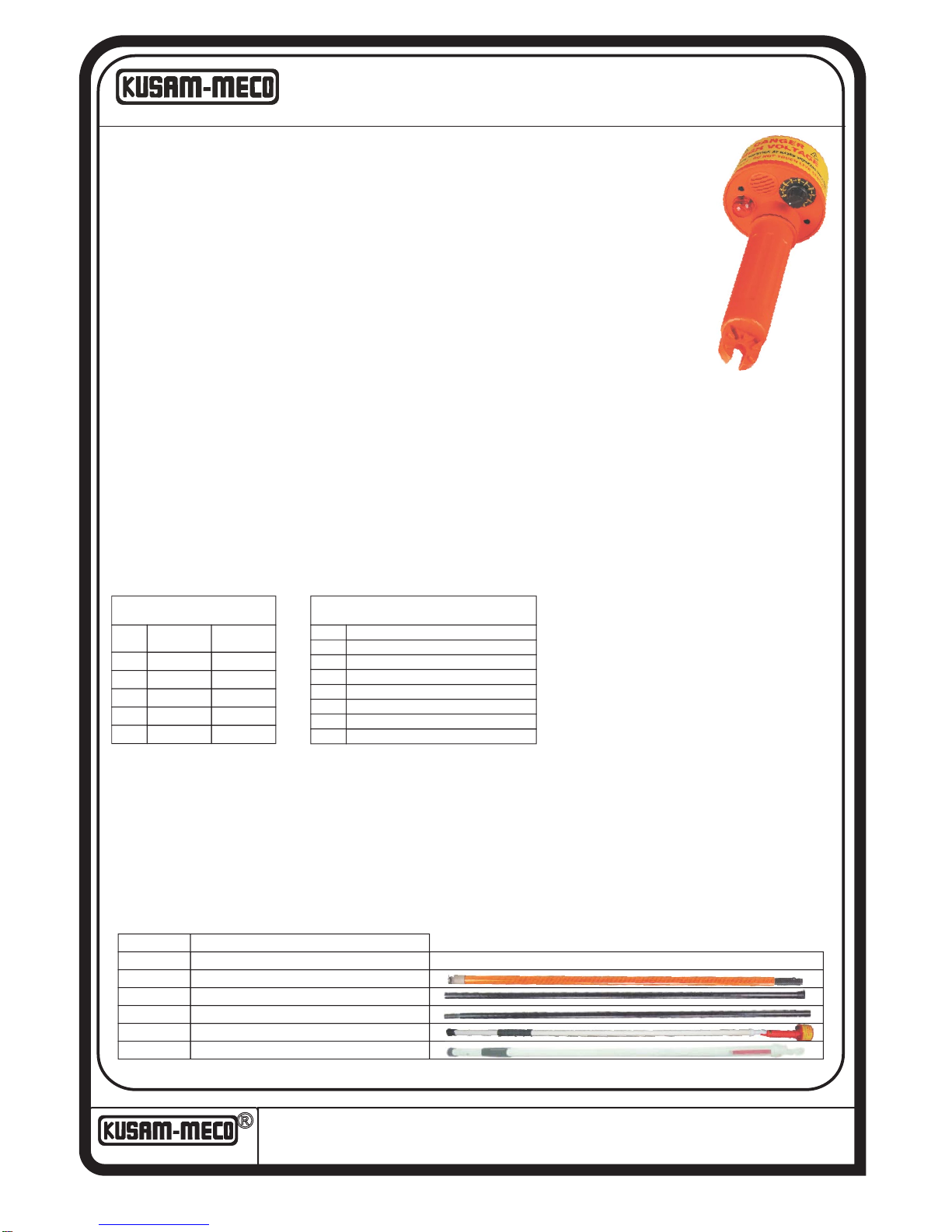
®HIGH VOLTAGE PROXIMITY DETECTOR
Model 275 HP (Upto 275KV) / 500 HP (Upto 500KV)
The 275HP / 500HP is a HIGH VOLTAGE proximity detector. 275HP has eight voltage detection settings from 240Vac to 275KVac. & 500HP
has 10 Voltage detection settings from 240V to 500KV. The 275HP / 500HPconsists of an internal pickup sensor plate, a sensitivity selector,
a visual and a sound annunciator. With the 275HP / 500HP physical contact with electrical conductors is not necessary when testing for live
lines. This tester works by proximity.
Checking or proofing the tester is easy. Switch the sensitivity to 240V AC and place the dome against a low voltage live conductor or rub the dome with a cloth or
against an item of clothing as this generates a static DC which triggers the detection of circuit. The light and beeper should go “on” as if a live wire is being approached.
Approaching the dome near a computer screen or a TV screen (not liquid crystal display type) should also trigger the tester while on 240V selection.
Its sensor senses the radiated field which surrounds live conductors. Radiated field strength increases with voltage & decreases quickly with
distance or earth shielding. The radiated field from a cable of closely bunched conductors supplied by three phase power tends to cancel
(See “Limitations of use” paragraph). Detecting distance of a 250Vac single live wire is approximately 10cm. With a bunched neutral and
earth cable, as in a flexible cable, the distance is reduced to 5cm.
Some of the typical users are : identify and check live cables; find fault in flexible cables; check earth equipment; service neon lightning;
trace live wires; check high frequency radiation ; detect residual or induced voltages. For example, faults in damaged flexible cables are
found by applying low voltage to each conductor. Earthing the remainder and moving the tester along the cable until the change in condition
is obtained. (Flexible cables which are used in mining and building industries, are readily repairable when the break in the cable is located.)
When using for high voltage, the rotary switch (attenuator) is used to identify and differentiate various HV live cables. The tester must be
used in conjunction with a long and insulating rod when measuring high voltage (KV). However, the 275 HP / 500HP is a non contact
tester and it is advised that the tester should never come in to contact with cables (KV) as this tester is merely a non-contactAC proximity
tester.
FEATURES :
SAFETY:
?Meets EN61000-3-2; EN61000-3-3; EN61326-1; EN55011 EN61000-4-2; EN61000-4-3; EN61000-4-4; EN61000-4-5; EN61000-4-6; EN61000-4-11.
Typical observation of test
results made in the fields
11KV
22KV
33KV
132KV
275KV
Range MinDetection
Voltage (MDV)
MDV as % of
Line Voltage
1KV
2KV
3.1KV
12.5KV
22.5KV
9.1%
9.1%
9.4%
9.5%
8.2%
Expected test results
(laboratory testing):
Range Operated From
240V
2KV
6KV
11KV
22KV
Variable from 80V or depending on the type of source
250V
500V
33KV
132KV
1000V
1500V
4000V
8000V
LIMITATIONS OF USE :
It is recommended that the 275HP / 500HPis not used in HV yards of mixed voltages. In the presence of mixed voltages, the tester can become unreliable.
Problems can arise when the tertiary circuit of a 275/133/11KV transformer is tested. The electric field of the HV and MV bus bars can trigger the detector when it is
above 3m above the ground. This is common with most of the electric field voltage detectors, and the users should be aware of it. The tester can pick up adjacent
circuit to the one being tested and indicate the wrong information to the user.
8 Voltage Settings : 240V , 2KV, 6KV, 11KV, 22KV, 33KV, 132KV and 275KVAC (Model 275HP).
?10 Voltage Settings : 240V, 3.3KV, 11KV, 22KV, 33KV, 66KV,110KV, 220KV, 330KV, 500KV (Model 500HP).
?Self test selection.
?High bright LEDs visual indication.
?Sound indication.
?
?Non-contact work by proximity.
?Detect low voltage on any systems.
?Compatible with most link sticks.
?Use 3 x 1.5V “C” batteries
?Easy access to batteries.
?High impact nylon casing.
?Sealed by “0” rings
?Suitable for indoor and outdoor use.
?Light weight, robust, & compact.
?Weight :Approx. 500g.
The distance for detection of the voltage depends upon the
range selected & actual Voltage of the conductor.
e.g. If the range selected is PC11KV, the minimum distance for
detection of the PC11KV voltage is 22cm. But if the range
selected is PC22KV, you need to be closer (14cm) to detect
the PC11KV conductor.
HOT STICK Model HSR - 120 / 120A / 120B / 120C / 121 / 122
“KUSAM-MECO” Hot Stick is suitable for use with Non Contact High Voltage Detector Model 275HP & 500HP. It’s construction is Telescopic. It is constructed from
highly insulating reinforced Fibre Glass rod. The reinforcement gives high mechanical strength. It has a rubber gripper for holding it firmly when making
measurements of H.T. Lines. It is supplied with carry bag.
Model Length
HSR 120
HSR 120A
HSR 120B
HSR 120C
HSR 121
HSR 122
1 x 1.2m Orange stick & 3 x 1.8m Black stick.
1 x 3.0m Retractable stick.
1 x 5.0m stick.Retractable
1 x 1.2m Orange stick
1 x 1.8m Black stick
1 x 1.8m Black stick with handle
Combination of 3 Models Sticks HSR 120A, 120B & 120C

HI - PROX 275HP - TEST REPORT NOTES -
o
1. The distance for 10cm at an angle of 90 .
275HP
Setting Angle V for Sound and
G
Light Trigger Distance
MEASURED
240Vac
2kV
6kV
11kV
22kV
33kV
o
90
o
90
o
90
o
90
o
90
o
90
162Vac
1350Vac
4800Vac
10kV
14kV
27kV
10cm
10cm
10cm
10cm
10cm
10cm
From a distance of 10cm form the conductor, the 275HP can detect 162Vac while on the 240Vac
setting. From a distance of 10cm, it will however only start to detect 1350Vac on the 2kV position,
4800Vac on the 6kV position, 10kV on the 11kV position, 14kV on the 22kV position and 27kV on
the 33kV position.
o
2. The distance for 5cm at an angle of 90 .
The results are as follows :
275HP
Setting Angle V for Sound and
G
Light Trigger Distance
MEASURED
240Vac
2kV
6kV
11kV
22kV
33kV
o
90
o
90
o
90
o
90
o
90
o
90
90Vac
1300Vac
2800Vac
5500Vac
8200Vac
15500Vac
5cm
5cm
5cm
5cm
5cm
5cm
From a distance of 5cm form the conductor, the 275HP can detect 90Vac while on the 240Vac
setting. From a distance of 5cm, it will start to detect 1300Vac on the 2kV position, 2800Vac on
the 6kV position, 5500V on the 11kV position, 8200V on the 22kV position and 15500V on the
33kV position.
3. The Voltage of the generator (V ) set at a fixed voltage and the voltage setting on
G
the 275HP is selected on the rotary setting switch.
The Voltage setting of 240Vac position selected.
275HP
Setting Angle V on the
G
generator
Distance
For Detection
MEASURED
240Vac
240Vac
240Vac
240Vac
240Vac
240Vac
o
90
o
90
o
90
o
90
o
90
o
90
500Vac
1000Vac
2000Vac
6000Vac
11000Vac
22000Vac
32cm
48cm
75cm
124cm
146cm
226cm
If you don’t know the actual voltage to expect on a conductor, better try with
240Vac first. At 32cm, it will already detect 500Vac. While on the 240Vac position,
from a distance of 2.26Meter, you would detect a conductor with 22kVac.

4. The rotary setting selector is now positioned on the 2kV position.
The Higher the voltage, the smaller the distance of detection.
275HP
Setting Angle V on the
G
generator
Distance
For Detection
MEASURED
2kVac
2kVac
2kVac
2kVac
2kVac
2kVac
o
90
o
90
o
90
o
90
o
90
o
90
1000Vac
2000Vac
6000Vac
11000Vac
22000Vac
33000Vac
10cm
21cm
40cm
52cm
60cm
92cm
5. The rotary setting selector is now positioned on the 6kV position.
275HP
Setting Angle V on the
G
generator
Distance
For Detection
MEASURED
o
90
o
90
o
90
o
90
o
90
o
90
1000Vac
2000Vac
6000Vac
11000Vac
22000Vac
33000Vac
11cm
18cm
44cm
61cm
75cm
105cm
On the 6kV position, the 275HP detect 22000Vac from a distance of 75cm. On the previous test,
while on the 2kV position, the 275HP needed only 60cm to detect 22000V. So if you suspect the
conductor to be of a certain voltage, refers to the tables of these tests to help you approximating the
voltage.
6kVac
6kVac
6kVac
6kVac
6kVac
6kVac
6. The rotary setting selector is now positioned on the 11kV position.
As you increase the selected voltage on the rotary switch, you need more voltage on the
conductor to trigger the 275HP or you need to be closer (more volt per meter).
275HP
Setting Angle V on the
G
generator
Distance
For Detection
MEASURED
11kVac
11kVac
11kVac
11kVac
11kVac
11kVac
o
90
o
90
o
90
o
90
o
90
o
90
3500Vac
4000Vac
6000Vac
11000Vac
22000Vac
33000Vac
1cm
6cm
11cm
22cm
35cm
42cm

7. The rotary setting selector is now positioned on the 22kV position.
We increased the selection voltage to 22kV and now, you need to be closer to detect the 11kV
conductor. While on the previous test (11kV position), you could have been as far as 22cm before
detecting 11kV, now while on the 22kV position (position on the 275HP), you need to be as close as
14cm from the conductor to detect 11kV.
275HP
Setting Angle V on the
G
generator
Distance
For Detection
MEASURED
22kVac
22kVac
22kVac
22kVac
22kVac
22kVac
o
90
o
90
o
90
o
90
o
90
o
90
3000Vac
4000Vac
6000Vac
11000Vac
22000Vac
33000Vac
----
1cm
9cm
14cm
25cm
36cm
8. The rotary setting selector is now positioned on the 33kV position.
275HP
Setting Angle V on the
G
generator
Distance
For Detection
MEASURED
33kVac
33kVac
33kVac
33kVac
33kVac
33kVac
o
90
o
90
o
90
o
90
o
90
o
90
1000Vac
2000Vac
7000Vac
11000Vac
22000Vac
33000Vac
----
----
1cm
7cm
11cm
16cm
9. The rotary setting selector is now positioned on the 132kV position.
275HP
Setting Angle V on the
G
generator
Distance
For Detection
MEASURED
132kVac
132kVac
132kVac
o
90
o
90
o
90
18000Vac
22000Vac
33000Vac
1cm
7cm
10cm

®
17, Bharat Industrial Estate, T. J. Road, Sewree (W), Mumbai-400015. INDIA
Sales Direct: 24156638 (022)2412 4540, 2418 1649
Fax:(022)2414 9659 E-mail : [email protected],
Tel.:
WARRANTY
Each “KUSAM-MECO” product is warranted to be free from defects in
material and workmanship under normal use & service. The warranty period
is one year (12 months) and begins from the date of despatch of goods. In
case any defect occurs in functioning of the instrument, under proper use,
within the guarantee period, the same will be rectified by us free of charges,
provid ed the to a nd fro freight charges a re b orn e by you.
This warranty extends only to the original buyer or end-user customer of a
“ K U S A M - M E C O ” a u t h o r i z e d d e a l e r .
This warranty does not apply for damaged Ic’s, fuses, disposable batteries,
carrying case, test leads, or to any product which in “KUSAM-MECO’s”
opinion, has been misused, altered, neglected, contaminated or damaged by
acc ide n t or a bn o rma l co n dit ion s of o p er a tio n or h a nd l in g .
“KUSAM-MECO” authorized dealer shall extend this warranty on new and
unused products to end-user customers only but have no authority to extend a
gr ea te r o r diffe rent wa rr anty on be ha lf of “KUSAM -M EC O” .
“KUSAM-MECO’s” warranty obligation is limited, at option, free of charge
repair, or replacement of a defective product which is returned to a “KUSAM-
MECO” authorized service center within the warranty period.
THIS WARRANTY IS BUYER’S SOLE AND EXCLUSIVE REMEDY AND IS
IN LIEU OF ALL OTHER WARRANTIES, EXPRESS OR IMPLIED,
INCLUDING BUT NOT LIMITED TO ANY IMPLIED WARRANTY OF
MERCHANTABILITY OR FITNESS FOR A PARTICULAR PURPOSE.
“KUSAM-MECO” SHALL NOT BE LIABLE FOR ANY SPECIAL, INDIRECT,
INCIDENTAL OR CONSEQUENTIAL DAMAGES OR LOSSES, INCLUDING
LOSS OF DATA, ARISING FROM ANY CAUSE WHATSOEVER.
All transaction are subject to Mumbai Jurisdiction.
An ISO 9001:2008 Company
HIGH VOLTAGE A.C.
PROXIMITY DETECTOR HI-PROX
INSTRUCTION MANUAL
Model : 275HP

®
INDEX
Safety Rules
.................................................
03
04
General Description
.....................................
05
Low Voltage Testing
.....................................
Page
Front Panel Layout
.......................................
06
Preparation for Use
......................................
07
Checking and Proofing the Unit 07
...................
Typical Uses 08
..................................................
Broken Wires in Cables 08
...............................
High Voltage Testing 09
.....................................
09
Limitations of the 275HP Hi-Prox ................
Laboratory and Field Test Result 10
.................
Changing Batteries 10
......................................
11
12
Specifications
Limited Warranty
...............................................
...........................................
Caution, risk of electric shock.
Caution, refer to the user manual.
02
®
Specifications
Electrical
Detecting Ranges
Selection
Detects voltage from
240V
2kV
6kV
11kV
22kV
33kV
132kV
275kV
Variable from 80V
or depending on type of source
250V
500V
1000V
1500V
4000V
8000V
22kV
Mechanical
Bump Test :
Vibration Test :
Drop Test :
Impact Test :
Case Height :
Case Width :
Weight :
IEC68-2-29
IEC1010, clause 8.3
IEC1010, clause 8.4
IEC1010, clause 8.2
229 mm
96 mm
0.59 kg ( Batteries included )
Environmental
Operating Temperature :
Storage Temperature :
Humidity :
Cold Temperature :
Dry Heat :
Damp Heat :
-15°C to + 55°C
-20°C to + 65°C
93% RH @ 40°C
IEC68-2-1
IEC68-2-2
IEC68-2-3
11

®
03
Safety Rules
The 275HP Hi-Prox has been designed with safety in mind.
However, no design can completely protect against
incorrect use.
Electrical circuits are dangerous and lethal through
lack of caution or poor safety practice. The following
rules should reduce the danger:
Read the user manual carefully and completely before
using the tester. Fully understand the instructions before
using this product. Follow the instructions for every test.
Take all the necessary precautions. Do not exceed the
limits of this instrument.
The 275HP Hi-Prox must never be in physical contact
with any conductor higher than 1kV. This is a proximity
detector, not a detector which works by contact.
Always use a fiber glass rod or any authorized stick.
A high voltage test is carried out with the tester attached to
an operating stick, sometimes called “links stick”.
Verify the rotary switch setting before measuring. Make
sure it is on the correct setting for your application.
Always check that the 275HP Hi-Prox is working before
and after the test.
Do not touch any exposed wiring, connections, or other
“live” parts of an electrical circuit.
This instrument should only be used by a competent,
suitably trained person who understands this test
procedure fully. Personnel working with high voltage
should be trained regularly.
®
Laboratory And Field Test Results
Expected test results ( laboratory testing )
Range Operated from
240V
2kV
6kV
11kV
22kV
33kV
132kV
275kV
Variable from 80V
or depending on type of source
250V
500V
1000V
1500V
4000V
8000V
22kV
Typical observation of test results made in the
field
Range Voltage(MDV) Line Voltage
Min. Detection MDV as % of
11kV
22kV
33kV
132kV
275kV
1kV
2kV
3.1kV
12.5kV
22.5kV
9.1%
9.1%
9.4%
9.5%
8.2%
Changing Batteries
The 275HP Hi-Prox uses 3x1.5V “C” cells batteries. Open
the battery cover (turn counter-clockwise) to remove the
batteries. Ensure polarity is respected.
10

®
High Voltage Testing
The rotary switch (attenuator) is used to identify and
differentiate various HV live cables. The tester must be
used in conjunction with a long and insulating rod when
measuring high voltage (kV).
Non-Contact
It is advised that the tester should never come into contact
with cables (kV) as this tester is merely a non-contact AC
proximity tester.
Limitations On The 275HP Hi-Prox
It is recommended that this tester is not used in HV
yards of mixed voltages. In the presence of mixed
voltages, the tester can become unreliable.
Problems can arise when the tertiary circuit
of a 275/133/11kV transformer is tested. The
electric field of the HV and MV bus bars can
trigger the detector when it is about 3m above
the ground. This is common with most of the
electric field voltage detectors. Users should
be aware of it. The tester can pick up
adjacent circuit to the one being tested and
indicates the wrong information to the user.
09
®
General Description
The 275HP Hi-Prox consists of an internal pickup sensor
plate, a rotary switch as sensitivity selector, a sound
annunciator (high pitch, high power buzzer), a visual
indicator (high bright LEDs), and three “C” size batteries.
The 275HP Hi-Prox detects AC voltages using the sensor
plate. The sensor plate collects part of the radiated electric
field (V/M). The electric field is seen by the internal circuitry
and triggers the input of a CMOS integrated circuit. The
integrated circuit charges a capacitor via a diode. Once that
capacitor reaches a certain level, the buzzer and LEDs
annunciator are turned “ON”.
The trigger level is fixed (CMOS logical level change). The
“self-test” inserts a voltage on the sensor plate, just like if the
sensor would pick up a voltage. The 275HP Hi-Prox allows
identification of AC voltages from 220Vac to 275kVac. The
enclosure is made out of industrial grade polyurethane. The
enclosure can be attached to a link stick. The small cylinder
part of the 275HP Hi-Prox fits into most link stick adaptors.
04

®
Low Voltage Testing
The 275HP Hi-Prox works by proximity. Physical contact
with electrical conductors is not necessary when testing for
live lines. Its sensor senses the radiated field which
surrounds live conductors. It is recommended not to touch
high voltage wires with the 275HP Hi-Prox.
Radiated field strength increases with voltage and
decreases quickly with distance or earth shielding. The
radiated field from a cable of closely bunched conductors
supplied by three phase power, tends to cancel (See
“Limitations of the 275HP Hi-Prox” on page 9).
Detecting distance of a 250Vac single live wire is about 10
cm and with a bunched neutral and earth cable, as seen in a
flexible cable, the distance is reduced to 5 cm.
05
®
Typical Uses
Identify and check live cables
Check and detect live high voltage cables (using
extension hot stick)
Find fault in flexible cables
Check earth equipment
Service neon lighting
Trace live wires
Check high frequency radiation
Detect residual or induced voltages
Broken Wires In Cables
Faults in damaged flexible cables are found by applying low
voltage to each conductor. Earthing the remainder (the
wires that do not need to be traced. Do not earth the live
wire, so that they can be detected by the 275HP Hi-Prox.)
and moving the tester along the cable until the change in
condition is obtained. (Flexible cables, as used in mining
and building industries, are readily repairable when the
break in the cable is located).
08

®
Preparation for Use
When unpacked, the tester should be inspected for any
visible signs of damage, and the preliminary checks
described in the user manual should be performed to ensure
that it is operating correctly. If there is any sign of damage,
or if the instrument does not operate correctly, return it to
your nearest supplier.
This instrument is powered by three “C” type batteries.
Checking And Proofing The Tester
Switch the sensitivity to “SELF-TEST”. The buzzer of the
275HP Hi-Prox should beep and the LEDs should light.
This indicates that the 275HP Hi-Prox is operational.
Verify the working of this unit by selecting 240Vac and place
the dome against a low voltage live conductor or rub the
dome with a cloth or against an item of clothing as this
generates a static DC which triggers the detection of circuit.
The light and beeper should go “on” as if a live wire is being
approached.
Approaching the dome near a
computer screen or a TV screen
(not liquid crystal display type)
should also trigger the tester
while on the 240V selection.
2kV
240Vac
6kV 11kV
22kV
33kV
132kV
275kV
OFF
Self
Test
07
®
Front Panel Layout
OFF
Self-Test
240Vac
2kV
6kV
11kV
22kV
33kV
132kV
275kV
Buzzer
LEDs
Battery Holder
- Turn the pick-up sensor off
- Check if the entire circuitry is working
- 240Vac selection
- 2kVac selection
- 6kVac selection
- 11kVac selection
- 22kVac selection
- 33kVac selection
- 132kVac selection
- 275kVac selection
- High noise level buzzer
- High bright low current LEDs
Buzzer
Rotary Selector
LEDs
Battery Holder
06
This manual suits for next models
1
Table of contents
Other Kusam-meco Security Sensor manuals
Popular Security Sensor manuals by other brands

STEINEL
STEINEL IS 360 D TRIO operating instructions

B.E.G.
B.E.G. LUXOMAT LC-Click 140 Installation and operation instruction

Gewiss
Gewiss CHORUS GW 13 756 installation instructions

Winland
Winland WaterBug WB-800 Installation & operation instructions

IMI SENSORS
IMI SENSORS 682B05 operating guide

CAME
CAME R Series manual