Kuzma 313VTA User manual

1
KUZMA STOGI REF 313VTA TONEARM
Instruction manual Serial Number: …..
2009-11

2
KUZMA LTD
INSTRUCTION MANUAL FOR 313 VTA tonearm
The Stogi Ref 313VTA tonearm is a very precisely engineered piece of equipment, however,
the construction is robust and requires minimal maintenance for optimal performance.
Fig.1
CONTENTS: Page
General description 3
Basic Setup 4
Setting up the tonearm 4-5
Adjustment of tracking force 6
Adjustment of tangential geometry 6
Adjustment of VTA 6
Adjustment of azimuth 7
Adjustment of bias 7
Adjustment of cueing device 8
Maintenance 8
Transport 8
Problems 8
Appendix 1 (tangential geometry) 9-11
Appendix 2 (fine azimuth) 12
Appendix 3 (fine bias) 13
Protractors 14
VTA tower&knob VTA lock
azimuth lock
Cueing device adjust. azimuth adjustmentRing fixing

3
General description :
The whole construction is mounted on a rigid VTA tower which allows very precise VTA
adjustment while playing, without any loss of rigidity, yet with up to 0.01 mm of precision
and zero play.
The main tube is constructed and machined from solid aluminium, similar to our tangential
Air line arm. The main counterweight balances the tonearm. Azimuth can be adjusted in
small repeatable increments with zero play, by means of an Allen key.
A feature of the tonearm is a unique detachable headshell. The electrical connection is via
standard pins but the headshell can be simply removed by unscrewing with an Allen key. The
headshell is fixed with a precise hexagonal locking system giving the same rigidity as with a
fixed headshell. The tonearm itself is mounted in the standard position, despite its longer
effective length.
Technical data:
Mass: 1700 gr
Effective length : 313 mm ( 12,3 inch)
Mounting distance: 212 mm
Offset angle: 17.50 degrees
Distance from spindle to
horizontal bearing: 300 mm
Effective mass: 13 g
VTA adjustment: yes
Azimuth adjustment: yes
Bias adjustment: yes
Cables: single
Arm mount: Kuzma-Air line

4
1. Unpacking
Open the box carefully and remove the top covers.
First remove the armbase and prepare it for fixing onto the turntable. Be sure that the
armboard on the turntable has the correct cut-out (main central hole must be 40 mm in
diameter).
2. Basic set up
Armbase:
Mount the armbase on the turntable. If the pre-cut has a thread, then use three screws and fix
them from the top through the armbase into the armboard thread. A second way is to use a
ring underneath and fix three screws into this ring, which will then hold the armbase very
tightly. Be sure that you position the armbase so as to give access to an Allen key for fixing
arm into the armbase (towards the back of the turntable). Also check, when mounting the arm
on other turntables, that you allow enough clearance for counterweights and correct position
of the tube in relationship to the platter.
VTA arm tower:
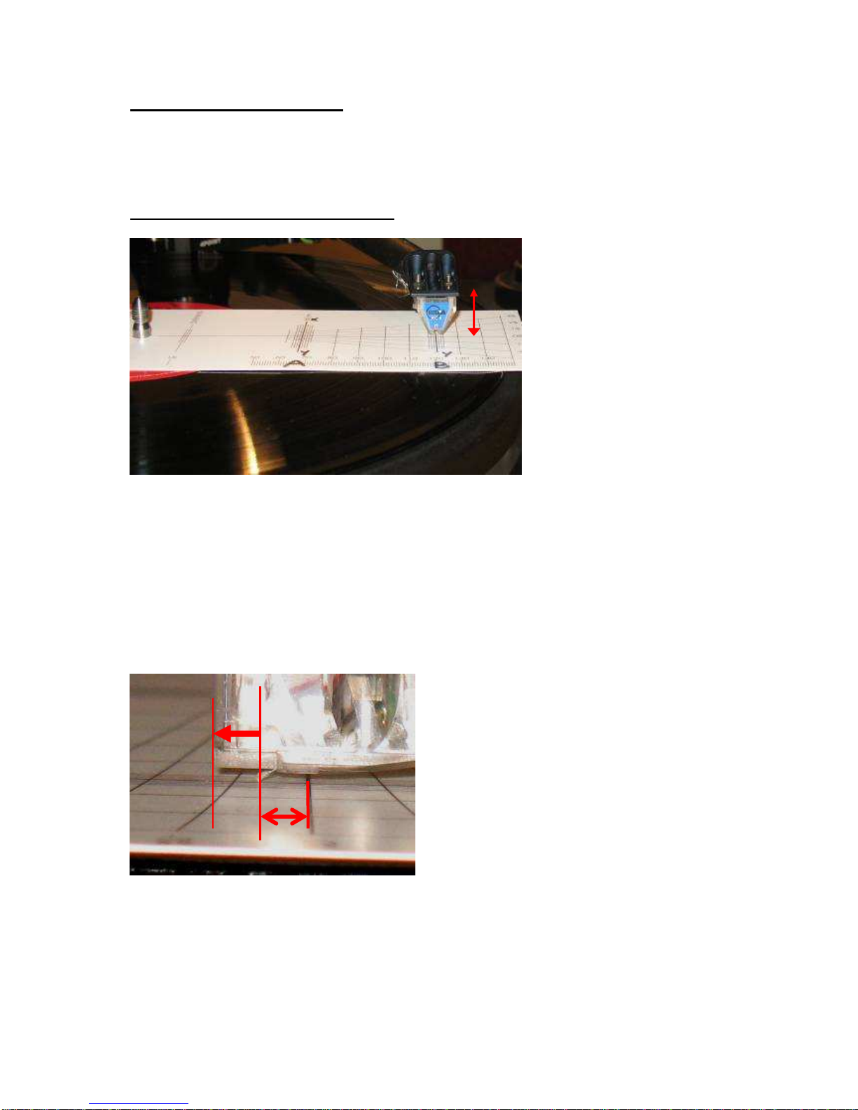
Insert the VTA arm tower into the armbase. Ensure that the height is such, that the bottom
surface of the platform holding the cueing device is at the same height as the record. Fix it
with an Allen key. Also check that the VTA adjustment is in the middle position, to allow fine
VTA adjustment up and down 5 mm each way.
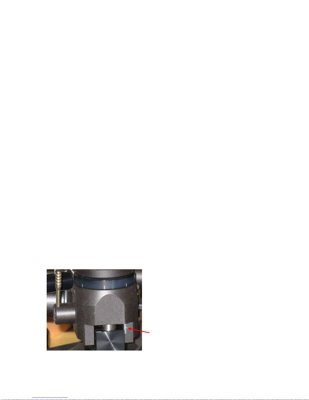
With 1.5 mm Allen key, release the small ring which is on the fixing pillar below the VTA
arm tower. Now it will drop down and touch the armbase. Fix the ring again and release the
VTA arm tower. You now have the correct height but you can freely rotate the VTA arm
tower horizontally. Rotate it to such a position that the distance from the centre of the record
to the centre of the horizontal bearing is 300 mm. Now fix VTA arm tower.
3. Setting up the tonearm
Connecting tonearm:
Check the horizontal movement of the tube to ensure that the headshell will reach the inner
grooves.
Due to the high tonearm mass, turntable levelling and suspension should be checked and
adjusted according to the turntable manual.
Cartridge mounting:
Mount the cartridge with the appropriate set of 2.5 mm screws and check its travel above the
record with cueing device in upper position!

5
Headshell removal and fixing:
This tonearm has a detachable headshell and fixing and positioning it has no negative effect
on tonearm performance. The whole headshell is fixed with one Allen key 2 mm. Insert it in
the top hole and release screw with Allen key for at least one turn (ACW). (Fig.2&3)
Disconnect cartridge pins, remove Allen key and pull out the headshell. (Fig.4)
Fix the cartridge and return headshell back in to the tube. If it can not be inserted easily,
rotate the screw a little more in ACW direction. Then fix it back in CW direction with gentle
force, around one turn.
Fig.2 Locked Fig.3 Unlocked
Note: Do not over-tighten the screw which locks the headshell.
Fig.4 Removing headshell
Balancing of the tonearm:
Fix cartridge pins. Balance the tonearm to zero tracking force by rotating counterweight along
the thread.

6
4. Adjustment of tracking force
Balance the tonearm with the tracking scale, which must be at record height. Rotate the
counterweight towards the tube to increase tracking force. Rotating the counterweight for
one red dot changes tracking force for approximately 0.15 g.
Check that the cueing device is at the correct height (see paragraph 9)!
5. Adjustment of tangential geometry
Put a record on the platter and adjust VTA in such a way, that the central axis of the tube will
be parallel to the record. This is only a starting point for VTA.
Using the protractor, adjust geometry at two null points. Rough guidance is by the edges of
the cartridge body, but accurate adjustment is by observing whether the cantilever and lines
are parallel at the two null (zero) points.
See appendix 1.
6. Adjustment of VTA
It is extremely easy to set up VTA on this tonearm. Just unlock the lever at the back and
rotate the VTA knob. VTA knob rotation CW- VTA down (Fig.1)
VTA adjustment between any two lines is 0.1 mm (the whole rotation is then 0.8 mm) which
allows for very fine repeatable adjustment. The rigidity of the assembly is such that even in
the unlocked position you will not feel slack. Move the tonearm VTA to the desired height.
Simply lock the lever back with gentle force. Observe the 1 mm scale at the left hand side of
tonearm tower (Fig.5). If you run out of range (10 mm), then you must reposition the tonearm
height in the armbase. However take into account what is the optimal VTA by listening.
Once you find out the correct VTA, rotate outer ring of the VTA main knob and position it
into null position. This is now your starting point for very fine tuning.
Fig. 5 VTA tower side-rough scale

7
7. Adjustment of azimuth
To make azimuth adjustments, release the two screws locking the mechanism at the centre top
of the main tonearm tube, with Allen key 2mm. Under the main tube is a tiny rod with a
hexagonal screw. Insert the Allen key 2 mm into the screw (it may feel loose), rotate it
slightly and it will alter the azimuth. (Fig.1)
Rotating it back will bring azimuth to its previous position. Changes can be seen by
misalignment of the white lines on the top of the centre of the tube. Even 15 degrees rotation
of the Allen key will make a significant difference.
See appendix 2.
8. Bias
The bias should be adjusted roughly according to the tracking force. Using Allen key 1.5
mm, unlock the screw on the bias weight and position it to the equivalent of gap X to your
chosen tracking force. Lock the screw back, when in position.
Fig. 6 Bias adjustment
For maximum tracking, it is advisable to set the bias by use of an appropriate test record, ie.
those with tracking bands. Please do not use test records with blank space where the tip of the
needle sits on the surface rather than in the groove. (Fig.9&9a)
See appendix 3.
X P
mm gr
0 1.00
3 1.25
8 1.50
13 1.75
18 2.00
bias lock
X

8
9. Cueing device adjustment
Should you find that in the ‘up’ position the cartridge is too high or too low above the record
then the cueing device can be raised or lowered. This can be done simply by using Allen key
1.5 mm:
Insert key into screw on side of arm rest.
Release screw, raise or lower device and retighten.
Rotation of cueing device can affect the drift of cartridge while travelling vertically down.
The cueing device may lift slightly as the screw is retightened. Do not over-tighten as this
may cause the cueing device to stick in the ‘up’ position. Should this occur, slightly release
the screw. (Fig.1)
10. Maintenance
The bearing does not need maintenance. Clean dust from the tonearm with a soft cloth.
11. Transport
During transport the tube should be locked in the armrest and counterweight removed.
12. Problems
1. Cartridge jumps in the inner grooves: See if the tube can travel towards the centre of the
record- check that position of the tonearm is correct with protractor for distance.
2. Cartridge is too close to the record edge: Check if the tube travels too much toward the
centre of the record- check that position of the tonearm is correct with protractor for distance.
3. Headshell cannot be removed- check that the screw is released enough with Allen key.
Kuzma Ltd
Hotemaze 17A
SI-4205 PREDDVOR
SLOVENIJA
P: +386 4 25 35 450
F: +386 4 25 35 454
www.kuzma.si

9
APPENDIX 1
Tangential Cartridge geometry adjustment
Once the cartridge has been mounted, it is necessary to ensure that the cartridge is tangential
to the record grooves in order to minimize tracking distortion during playing. As the cartridge
moves in an arc across the record, tracking distortion occurs and is minimized by the tonearm
geometry and the angle of the cartridge in the headshell.
With optimum tonearm geometry, very low distortion levels (below 1 %) can be obtained
across the entire playing surface. Cartridges have zero distortion at two points on a record
and these points are used when aligning the cartridge. In practice these points lie at 66 mm
and 121 mm from the record centre (see protractor). Other protractors make use of different
zero points due to the use of different parameters in calculation. In this case 60 mm has been
chosen as the inner groove and 146 mm as the outer groove which still has optimum tracking
distortion.
1. Ensure bias is on minimum or switch off.
2. Place protractor over spindle on platter.
Note:
If you have difficulty seeing the cantilever it may help to raise the arm a few mm, taking care
that the protractor does not rotate. This also prevents tilting of the cantilever due to the effect
of bias force. It may also be helpful to fix the platter by inserting a wedge between platter and
plinth and by inserting a sheet of white paper to give a clear background while observing the
cartridge. Use a strong light.
3. Alignment at zero point 66 mm (A):
Place tip of stylus on point A (ie. zero point 66 mm). With a strong light observe cartridge
from front. The cantilever and the line on protractor should be in perfect alignment.
If the cantilever is not, then the body of the cartridge will have to be rotated slightly.
Do not adjust cartridge by observing body of cartridge only. (Fig.14)
Fig. 14 Alignment at A

10
To rotate or readjust cartridge:
4. Slightly loosen the screws which attach the cartridge to the headshell.
5. Holding headshell in one hand slightly rotate the body of the cartridge.
6. Recheck alignment at position A and continue adjustment until line described in point 3 is
achieved.
7. Alignment at zero point 121 mm (B):
Reposition protractor and check alignment at position B.
Fig. 15 Alignment at B
8. If the cantilever is not in alignment then rotate protractor until it is in alignment somewhere
along the line “x-y” though stylus will probably not be at zero point B. Raise the cueing
device a bit for better viewing. (Fig.15)
9. If stylus is in front of point B, pull the cartridge forward (along side) in the slots of the
headshell for approximately the same distance “S” as stylus is overhanging zero point B. If it
is behind point B, push cartridge backwards towards the pivots of the tonearm for distance
“S1” (Fig. 16)
Fig.16 Stylus tip is in front of zero point B.
“S”
B
“S”
0%

11
10. Now rotate protractor and again position stylus at zero point A as described in 5 and 6
above, ensuring that the position of the cartridge in the slots alongside is not changed but only
rotated for alignment of the cantilever in zero point A. (Fig.17)
Fig.17 Rotation at A
11. Recheck alignment of the cantilever at zero point B. If cantilever is not aligned here,
rotate protractor to find where on line “x- y” the cantilever is aligned again. (Fig.18&15)
Fig. 18 Alongside line “X-Y” alignment at B
If the stylus is still in front of zero point B on the line “x-y” as before, but nearer to point B,
then again pull cartridge slightly forward for distance “S” and repeat the whole process by
aligning at zero point A until the stylus will be at zero point B.
If stylus end up behind the zero point B on line “x-y” then move cartridge in opposite
direction to before, backwards and realign it at zero point A.
If stylus is still behind the B point, the cartridge should be pushed back and realign at zero
point A and realigned again at zero point B.
12. Continue until the stylus is in alignment at both points.
REMEMBER STEPS:
a) Put stylus at zero point A and by rotation align cantilever along XY line.
b) Align cantilever along XY line at zero point B by rotating protractor and see where stylus
is on the line XY- in front or behind zero point B.
c) Move cartridge along (not rotating it) for the same distance as stylus is overhanging zero
point B for the same distance to increase the overhang.
d) Repeating these steps (a,b,c,a,b,c,…) will ensure that stylus& cantilever are in alignment at
both zero points A&B.
NOTE: Ensure that cantilever is not twisted due to bias force.

12
Appendix 2
Fine Azimuth Adjustment
This can be done using an oscilloscope and a test record or by using good records in a good
system and listening to the sound. Cartridges with fine profiles (VDH, Microline etc.) are
more sensitive to this adjustment. On the other hand cheaper cartridges are not made so well,
making fine adjustment more useful.
With an oscilloscope we measure the differences in crosstalk between both channel. The idea
is that on both channels this is equally small. For that we need a test record with tracks
recorded for left and right channels separately. Then we compare crosstalk from the left
channel on the right channel- which is a very small signal, to the same type of signal from the
other channel. By adjusting azimuth, crosstalk on both channels should be made equal.
Listening from LP:
Start listening with the tube in zero position, with the marking lines aligned. Listen to the
sound-stage, the focus and the stability of the instruments. Release the two locking screws
and rotate the Allen key so that tube rotates for approximately the width of the mark. Listen
and then rotate tube for a similar amount in the opposite direction and again listen. Adjust the
arm to the position in which the best sound was obtained. In this position make further
adjustments by turning the Allen key for a quarter turn in one direction, listening and then
turning a quarter turn in the other direction and listening.
Continue this process making ever decreasing adjustments, 1/8 of a turn, then 1/l6 and so on.
When optimum results are obtained fix the locking screws. To remember the position of the
azimuth, imagine that the inserted Allen key acts as a dial on the clock.
NOTE: During fine adjustment only gently fix locking screws during listening.
The adjustment screw is highly sensitive and the smallest pressure on the Allen key will alter
the azimuth and sound.
Do not attempt any adjustment when the locking mechanism is locked. Although no damage
can be done.
Significantly improved sound can be obtained by paying attention to azimuth adjustment prior
to final VTA adjustment.

13
Appendix 3
Fine bias adjustment
1. Set bias and tracking force as previously described and listen to mistracking on highly
Modulated tracking bands on test record. On higher modulated bands mistracking can be
heard as impure tones and there will be more overtones. (See instructions on test record)
2. If mistracking is apparent, increase or decrease bias until minimum mistracking is found.
If mistracking is heard on the right channel only then the bias is too low, if on both
channels the bias is too high or the trackability limit of the cartridge has been reached.
3. Finally further decrease mistracking by increasing tracking force to the maximum
Recommended for the cartridge.
4. It is best to have the highest possible tracking force and low bias force.

14
Cartridge Protractor ( Not in correct scale) Tonearm mounting protractor
A X Y
S
B X Y
This manual suits for next models
1
Table of contents
Other Kuzma Turntable manuals

Kuzma
Kuzma Kuzma Stabi Reference Turntable User manual

Kuzma
Kuzma Air Line User manual

Kuzma
Kuzma Air Line User manual

Kuzma
Kuzma Stabi S User manual

Kuzma
Kuzma XL AIR KIT User manual

Kuzma
Kuzma Stogi S User manual

Kuzma
Kuzma 4Point User manual

Kuzma
Kuzma Stabi XL User manual

Kuzma
Kuzma Stabi S12 User manual

Kuzma
Kuzma Stogi S User manual

Kuzma
Kuzma STABI REF PS 2 User manual

Kuzma
Kuzma STABI R User manual

Kuzma
Kuzma 4Point User manual

Kuzma
Kuzma STABI R User manual

Kuzma
Kuzma STABI M User manual

Kuzma
Kuzma XL DC User manual

Kuzma
Kuzma Stabi S PS User manual

Kuzma
Kuzma Stabi XL2 User manual

Kuzma
Kuzma STABI S PS AC User manual

Kuzma
Kuzma Stabi XL4 User manual