Kuzma Stabi XL User manual

1
KUZMA STABI XL TURNTABLE (with Air line tonearm)
Instruction manual

2
KUZMA LTD
INSTRUCTION MANUAL FOR STABI XL turntable
The Stabi XL turntable is a very precisely engineered piece of equipment. However the
construction is robust and requires minimal mainentance for optimal performance.
CONTENTS: Page
General 3
Unpacking 4
Basic Setup 5-6
Setting up turntable 7-8
Use and Adjustment 9
Mainentance 10
Problems 11

3
General Description: The turntable is packed in three boxes. Some parts are very heavy so
handle boxes with care .
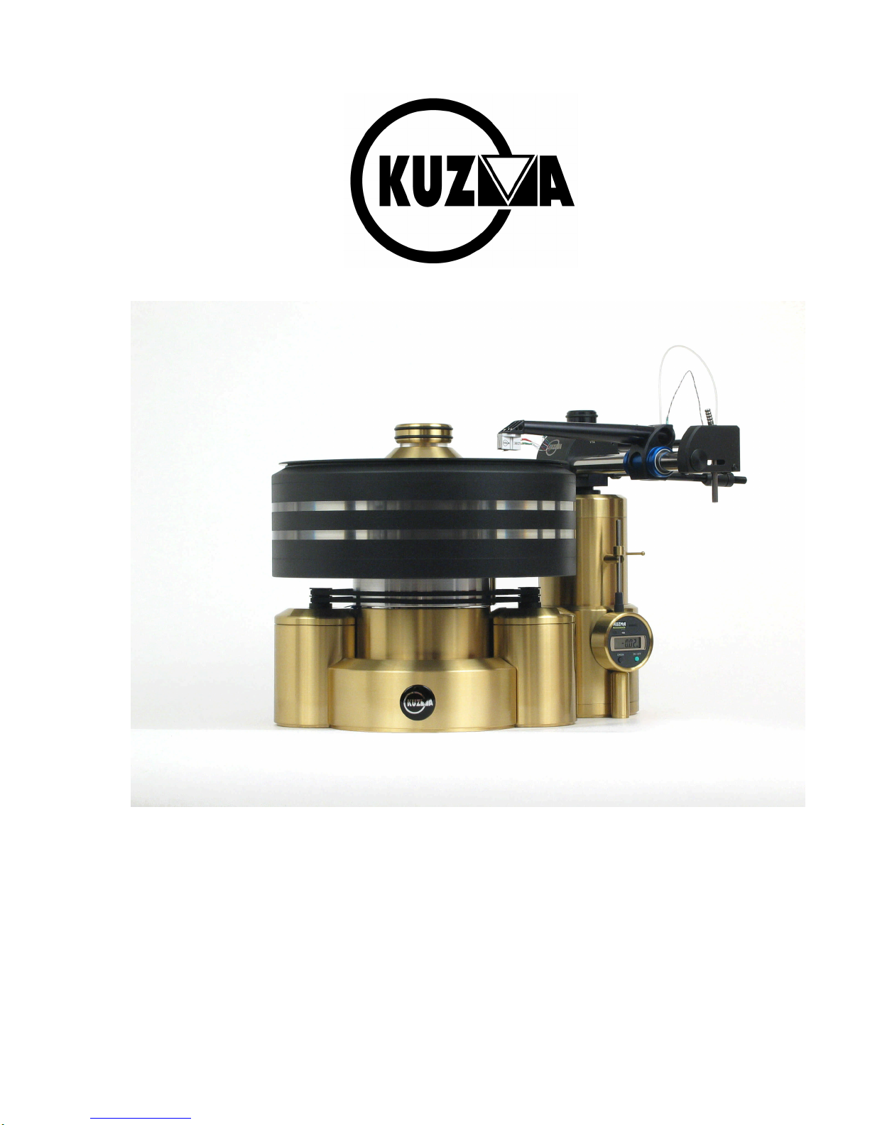
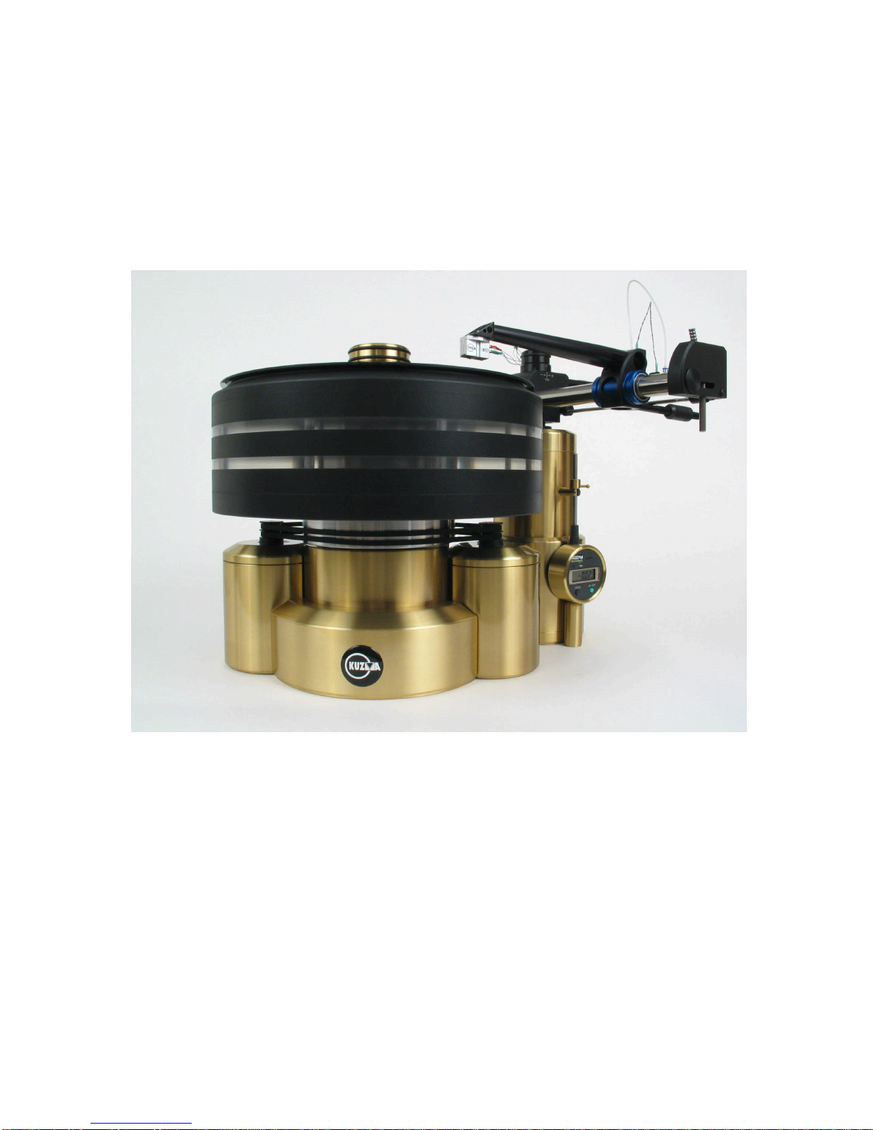
The base is of solid brass which is clamped together from two pieces and has good damping
properties. The main shaft, which is 28 mm in diameter, is fixed into this base. The platter is
a sandwich construction of aluminium and acrylic plates screwed together in a pre-stressed
form to damp all unwanted vibration. Hard non-metalic material is used for the bearing
which, together with a ruby ball, is lubricated in an oil pool to provide one point contact
ensuring minimal vibration and noise. The position of the platter is further stabilised by a
sliding non –metal ring, precisely matched to the shaft diameter and immersed in a second
large oil pool.
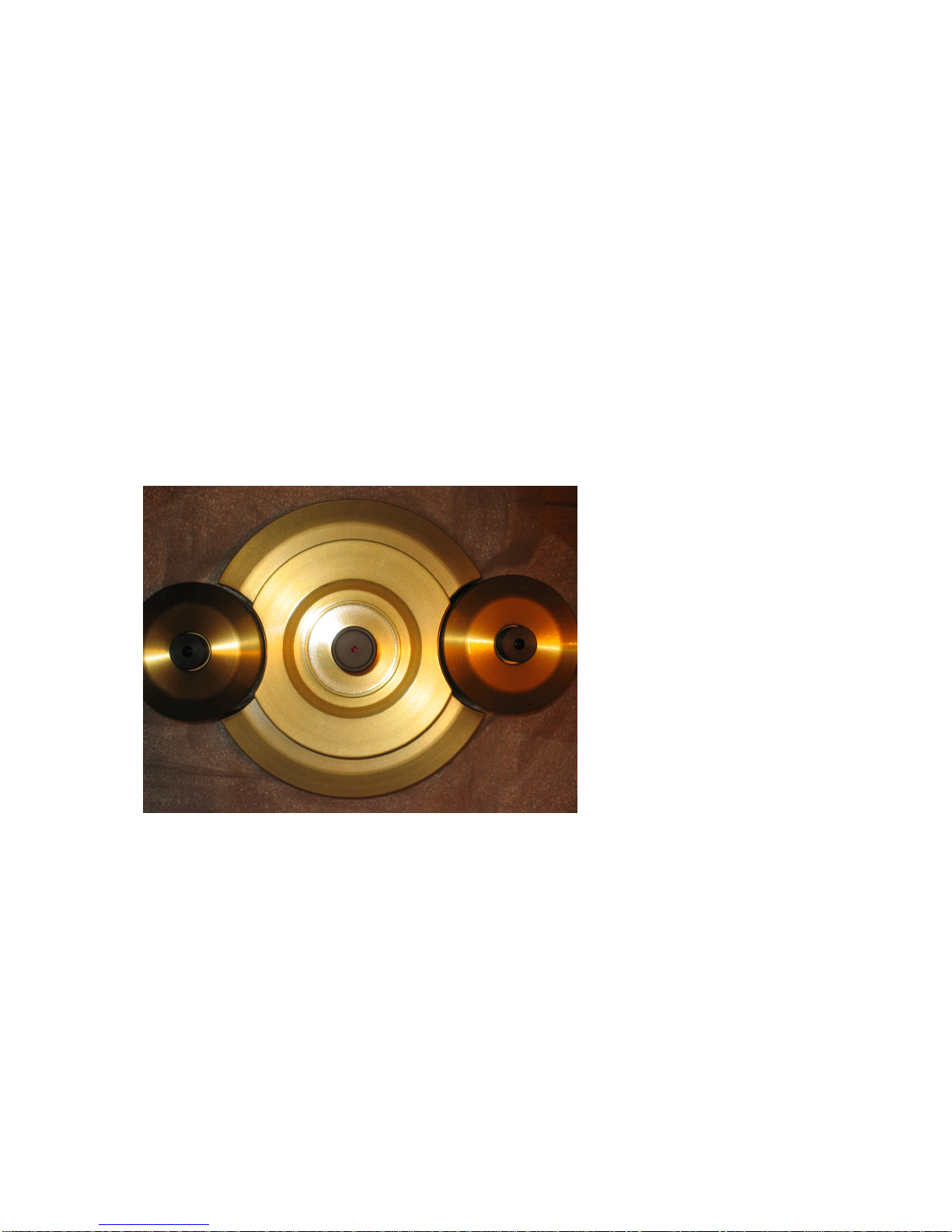
Two motors are mounted separately in their own heavy brass towers. Two pulleys, via two
belts, give stable symetrical drive to the subplatter. The electronic power supply generates
controlled feed from a quartz to both motors, in such a way that the vibration of the motors is
minimised. A heavy threaded brass and acrylic clamp provides additional damping of
vibration caused by playback, as well as flattening curved records. The record is pressed
securely to the platter-mat, which is a semi-hard combination of rubber and textile.
The tonearm tower is a massive brass unit and the armboard can be exchanged to
accommodate various tonearms. The mass of the tower gives structural and damping rigidity
to the tonearm. The unit allows for VTA adjustment during playback without loss of rigidity
or azimuth. The movable part is supported via a linear ball bearing 30 mm in diameter and
100 mm in length. This gives firm support while allowing VTA to be changed. Adjustments
can be made over a range of 60 mm, each turn of knob representing 1 mm precisely. In order
to simplify adjustment, a micrometer gives a digital readout over a range of 12mm at an
exactitude of 0.01 mm. These adjustments are repeatable.
Stabi XL turntable :Technical data
Mass (total w/o PS) : 77kg
Platter: 22 kg
Base: 27kg
Motor towers: 2x 7kg
Tonearm tower: 14 kg
Speeds (fine adjust): 33, 45 rpm
Dimension: 450x 400 x 300 mm
Power supply: 110V or 240 V , 50/60Hz (factory set)
Optional: use of more than one tower, tower without VTA for Air Line tonearm,
Safety Precautions:
Electrical connection to the power supply from the mains comes via the cable. Please keep
PS away from moisture and be careful not to damage the mains cable. The same precaution
applies to cables feeding the motor towers.

4
Unpacking:
Stabi XL comes packed in three boxes. Be aware that the two larger boxes are very heavy.
These two boxes have double packaging. Inside are cutouts in the packaging blocks of firm
foam for various parts of the turntable. Some parts are very heavy, so handle with care while
lifting from the boxes and placing them on the assembly surface.
Contents:
Box 1:
Platter and two motor towers
Box 2:
Tonearm tower, base, subplatter, clamp, VTA guage.
Box 3:
Power supply, belts 2x, motor cables 2x, bearing oil bottle 2x, clamp washers 2x, power cord,
Allen keys: 1.5 , 2 , 2.5, 3 mm, Instruction manual.

5
Basic Setup:
Note: Some parts are very heavy, so be careful when handling!
Note: Choose a suitable supporting table which can hold over 80 kg without warping.
Note: While the parts are packed in plastic bags for protection, these are not intended to be
strong enough to lift or carry the contents.
Open all three boxes and remove top covers.
Base:
Locate the main brass base with the shaft. This is very heavy. Lift, being careful not to
scratch against metal parts of clothing, and position in the middle of the supporting board.
The Kuzma logo should face forward. Use a ruler to position the centre of the base.
Motor towers:
Remove the two brass motor towers with black pulleys being careful not to touch the pulleys
with any force. Position each motor separately in the rounded cutout on each side of the
main base, so that the connectors are at the rear side. The gap between the base and the motor
towers should be 2 mm and both perimeters should appear parallel. See Fig 1.
Distance of motors. Fig. 1.
Subplatter:
Remove the protection cover from the shaft and see if there are any dirt particles in the area
of shaft and ruby ball. Remove these using a soft cloth and further clean the area if
necessary with a cloth soaked in alcohol.
Oil should be poured into the reservoir on top of the shaft (where the ruby ball is located )
until it is full and oil starts to run into the lower reservoir. Then empty the rest of oil into
this lower reservoir. The level of oil is not critical due to the construction of the bearings.
Note: there is a spare bottle of oil!
Carefully put the aluminium subplatter over the shaft as vertically as possible and gently
lower by rotating it back and forth. When lowered, ensure that rotation of the subplatter feels
free and firm. If your hands are sweaty or sticky from the oil, clean the outer surfaces of the
subplatter with a cloth soaked in alcohol.

6
Belts:
Place one belt over both motor pulleys in the lower running grooves and subplatter and
check by manual rotation that the belt runs smoothly in the middle of the grooves. Then place
the second belt in the top running grooves on the motor pulleys and subplatter. Recheck the
position of belts. See Fig. on page 2.
Power supply (PS):
Position the PS on a firm surface away from signal cables and ensure there is adequate
ventilation, ie. leave a gap of at least 2 cm above the unit. Locate the 2 pieces of connecting
cables with DIN connectors. On the rear plate of the power supply and at the back of the
motor towers are DIN connectors, one for each motor. Connect cables by inserting plugs into
the sockets and rotate locking collars. It does not matter where each motor is connected. Plug
in the mains cable. Press the black switch on the front panel and the red LED should light
up. Rotate the brass knob to the 33 position, the red colour should change to green and the
subplatter should start rotating. Check the belts again to ensure they run smoothly in the
appropriate grooves.
Platter:
Carefully put the platter on the subplatter. The best way to do this is for one person to hold
the platter while another person positions it over the subplatter, helping to lower it down. Be
careful not to scratch the platter with jewellery etc. Check that the platter is resting on the
subplatter. Full speed should be obtained within 30 seconds (15-20). See front page.
Tonearm tower:
Position the tonearm tower in the approximate normal tonearm position. Ensure that the
tonearm tower is not touching the platter, base, or motor towers. Position the tower so that
the VTA toothed knob is facing away from the platter and that the parts holding the
measuring guage are facing towards the front. For Kuzma tonearms the gap between platter
and tower is 5 mm. See Fig. on page 2.
By rotating the VTA knob conterclockwise, raise the height of tonearm tower to slightly
below the top surface of the platter (10-20 mm). If your tonearm tower comes with an
appropriate cutout for your tonearm, measure the distance from the spindle to the centre of the
tonearm tower. When used with our tonearms this should be 212 mm. The top brass round
plate is removable and different tonearm cutout brass plates are available from your dealer.
Rotation of the top brass plate against the tonearm tower is easily done. Just release the two
side screws with Allen key 3 mm. The position of the tonearm tower in relation to the
perimeter of the platter does not affect the tonearm geometry, so the tower should be placed
for convenience of use. The only critical parameter is the distance to the platter centre.
Underneath the toothed VTA knob is a screw for securing the VTA , to prevent this being
accidentally changed ( using Allen key 1.5 mm).

7
Setting up the turntable:
Tonearm:
Ensure that the supporting stand is completely horizontal. When the Air Line tangential
tonearm is used additional fine adjustment of turntable horizontality is mandatory.
Mount the chosen tonearm according to instructions. Firmly secure the armbase onto the
tonearm top brass plate and secure it with two screws, using Allen key 3 mm, at the side of
the tower. See Fig.2
Fixing screws on top of the tonearm tower.Fig.2.
Raise the tonearm to an appropriate height above the platter. Position the tonearm cable
towards the back of the turntable towards the phono input. Check the length.
Check again the spindle to tonearm distance and rotate tower to be in an optimal operating
position.
VTA Guage:
Hang the digital display on the front of the tonearm tower using the lever and screw at the
bottom of the tower. Ensure that the display does not touch the platter or motor towers. See
Fig. on page 2.
The display can be left in the 'ON' position for up to three years (battery). Pressing 'origin'
will cause 0.00mm to show. Switching to + or –will cause this sign to appear in front of the
numbers. Pressing (press and hold for about one sec) to 'origin' again, resets the display to
zero. Due to the limits of height measurement (12 mm), the display should show the middle
of the measurement. An appropriate height for the tonearm is when the tube is parallel to the
record after the cartridge is mounted.

8
Setting the VTA Guage:
With Allen key 1.5 mm release the small brass weight which holds the display in the upper
position. The display will show minimum. Reset and the measurement will show zero. Lift
the vertical rod for about 6-7 mm (middle) and with Allen key, secure this position with the
screw on the brass weight. Then again reset and it will show that this new position is zero.
Raising the VTA by rotating the toothed knob, will show increased height above this
reference point in mm and lowering it will show minus numbers. The precision achieved by
this is 0.01 mm. If the change in height of the tonearm comes outside this range of
measurement, the brass weight can be repositioned. The measuring device will not be
damaged by being outside its range. Each rotation of the knob corresponds to 1mm change
in VTA and can even be moved while playing records.

9
Use and adjustments:
Platter rotation:
Ensure that the red LED lights up when switched on. Rotate the brass knob so that the red
dot matches the chosen speed.
Speed selection:
Select speed by rotation of the brass knob on the PS front panel. For 'on' the red LED
shows, for 33 rpm the green LED and for 45 rpm the orange LED. The power supply can be
left permanently switched on.
Fine Speed adjustment:
Fine speed change can be made by carefully rotating the small dial on the top of the PS with
a screwdriver. On the dial is an arrow which, when pointing to the small red dot nearby,
indicates precise 50 Hz output.
Turning the dial in a clockwise direction from the red dot lowers the speed (a total of 8 steps)
and in a counterclockwise direction the speed is increased, again for 8 steps in 0.05%
increments.
Clamp:
The clamp can be used without washers. Gently screw down the clamp on top of the record.
Put a washer under the LP (thin for thick records and thick for thin records) and start
screwing the clamp down. Observe the outer edge of the LP. To start with, this edge will be
above the mat but will slowly lower to touch the mat. With fingers hold the LP so that it
does not rotate. If the clamp is further screwed, the outer edge will rise. Pressure should then
be released by slightly unscrewing the clamp until the outer edge is touching the mat again.
This is the position in which the record is held in firmest contact with the mat.
Withpractise there is no need to stop spinning the platter while changing LPs or using the
clamp.
VTA change:
Rotation of the toothed knob at the base of tonearm tower raises and lowers the top part of the
tonearm tower (seen from the top, counterclockwise rotation raises VTA). Adjustments can
be in repeatable increments below 0.01 mm. Rigid construction allows for this to be done
while records are playing, without changing azimuth. For more details see the sections on
tonearm tower and VTA clock.

10
Mainentance:
Mat:
The top surface of the mat can be cleaned using a roller textile cleaner.
Bearing:
Oil in the bearing will last for 3-4 years or more. Running the bearing without oil will do no
harm due to the choice of materials and type of construction.
Oil should be added if the top reservoir (with ruby ball ) is totally dry. The oil level will be
below the ruby ball as, when the subplatter is lowered onto the shaft, the bearing surface
increases the level of oil above the ruby ball. When the subplatter is removed you can see the
level of oil inside its sliding ring ( brown colour). If it is above the sliding ring in the
subplatter, there is plenty of oil. If excess oil is added it will run into the appropriate extra
reservoir.
Belts:
Periodically remove the platter and remove the belts. Clean belts and running surfaces of the
motor pulleys and the subplatter with a soft cloth soaked in alcohol (every 8-12 months).
For best performance replace belts every three years.
VTA Guage:
The sign 'B' in the top left corner of the clock indicates that the battery should be replaced.
Remove the battery cap by turning it counterclockwise with a coin and remove old battery
replacing with a new battery with the + side facing up. Secure the battery cap. Immediately
after the battery has been set, a meaningless display or 'E' will appear. This is quite normal
so merely continue to set up 'origin' again.

11
Problems:
Platter not rotating:
Power supply-check if the red LED is on
-check selector to 33 rpm
-check connection cables from PS to motor
Consult dealer or qualified electrician.
Very slow start:
Only one motor is connected or one output channel of the PS has failed. Remove the platter
and belts and check that the motor pulleys are rotating. If only one motor pulley rotates,
disconnect the mains and connecting cables from the PS and reconnect the non-rotating
motor to the output of the second motor to check is there is a motor failure or a failure of
the PS.
Transportation:
For short distances dismantle the platter, remove belts and disconnect all cables. The base
with the subplatter can be transported as one, providing that it will not be tilted, as this may
cause oil leakage.
All parts are heavy, however, and can be easily damaged by sliding around a transport
vehicle. Repacking in original cutouts and boxes is , therefore, recommended.
Kuzma Ltd
Hotemaze 17A
SI-4205 PREDDVOR
SLOVENIJA
Phone:+ 386 4 25 35 450
Fax: + 386 4 25 35 454
www.kuzma.si
Table of contents
Other Kuzma Turntable manuals

Kuzma
Kuzma Stabi XL4 User manual

Kuzma
Kuzma Stabi S PS User manual

Kuzma
Kuzma STABI REF PS 2 User manual

Kuzma
Kuzma Stabi S User manual

Kuzma
Kuzma STABI R User manual

Kuzma
Kuzma 4POINT 9 User manual

Kuzma
Kuzma 4Point User manual

Kuzma
Kuzma Stogi S User manual

Kuzma
Kuzma Stogi S User manual

Kuzma
Kuzma STABI M User manual

Kuzma
Kuzma XL DC User manual

Kuzma
Kuzma Kuzma Stabi Reference Turntable User manual

Kuzma
Kuzma 4Point User manual

Kuzma
Kuzma STABI S PS AC User manual

Kuzma
Kuzma XL AIR KIT User manual

Kuzma
Kuzma STABI R User manual

Kuzma
Kuzma Stabi XL2 User manual

Kuzma
Kuzma Air Line User manual

Kuzma
Kuzma 313VTA User manual

Kuzma
Kuzma Stabi S12 User manual