Kuzma 4Point User manual

1
Instruction manual
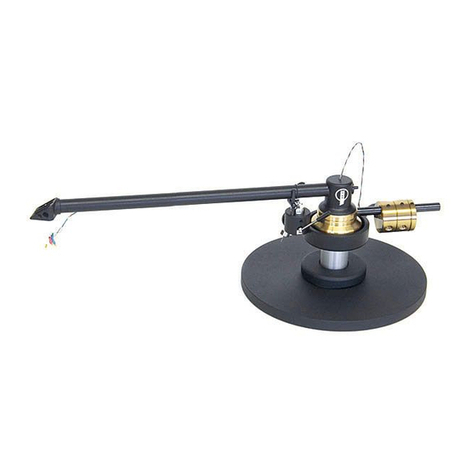
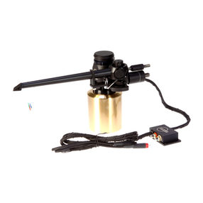
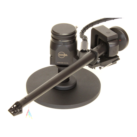
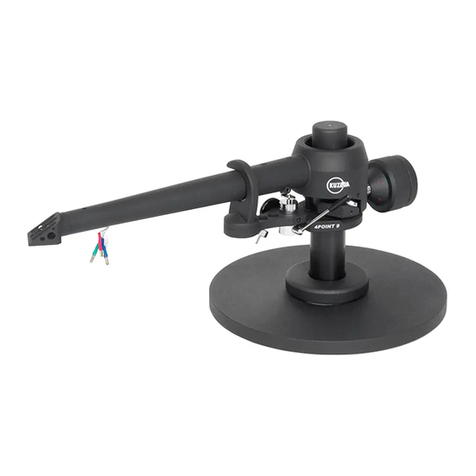
KUZMA 4POINT 14 inch TONEARM
Serial Number: …..
2016-09

2
KUZMA LTD
INSTRUCTION MANUAL OR 4POINT 14 tonearm
The 4POINT 14 tonearm is a very precisely engineere piece of equipment, however, the
construction is robust an requires minimal maintenance for optimal performance. It iffers from
stan ar 4Point ue almost 3 inches longer tube. It this requires ifferent mounting istance.
Fig.1
CONTENTS: Page
General description 3
Product registration and warranty extension 3
Technical data 4
Unpacking and Basic Setup 5-6
Setting up the tonearm 7-9
Adjustment of tracking force 9
Adjustment of tangential geometry 9
Adjustment of VTA 10
Adjustment of azimuth 10
Adjustment of bias 11
Damping 11-12
Adjustment of cueing device 12
Maintenance 13
Transport 13
Troubleshooting 13
hea shell lock vertical pa le vert. pa le lock horizontal bearing assembly VTA tower
VTA lock
Wire loop
pin for cable
cable - play position
counterweight tracking force
main counterweights horizontal trough lock trough–horizontal
horizontal pa le
main tube assembly
trough - vertical
fine VTA in icator
Armbase
lock screw

3
General description
This tonearm iffers from other arms by incorporating several unique features. The zero play bearing
is configure on 4 points (spikes). There is very precise VTA a justment an , espite a longer
effective length of 353 mm (14 inches), fits the mounting istance of 291 mm ( as for 12 inches
arms).
The heart of the new construction is a unique 4 point bearing. The first set of two points
(similar to a ouble unipivot bearings) allows vertical movement. The secon set of two points
allows horizontal movement. All four points have minimal friction an zero play in all playing
irections thus ensuring the cartri ge platform an the cartri ge itself to move with very low friction
an minimal vibration across the recor . It is normal to feel slack in the bearings in certain
irections.
The whole construction is mounte on a rigi VTA tower which allows very precise VTA a justment
while playing, without any loss of rigi ity, yet with up to 0.01 mm of precision an zero play.
The main tube is constructe an machine from soli aluminium. The counterweights set balances
the tonearm an there is a secon small counterweight with which the tracking force can be finely
a juste . Azimuth can be a juste in small repeatable increments with zero play, by means of an
Allen key.
A feature of the tonearm is a unique etachable hea shell ( one spare inclu e as stan ar ). The
electrical connection is via stan ar pins but the hea shell can be simply remove by unscrewing
with an Allen key. The hea shell is fixe with a precise hexagonal locking system giving the same
rigi ity as with a fixe hea shell.
Two separate troughs amp vertical an horizontal resonances an can be finely a juste
in epen ently. The troughs can be remove from the tonearm.
Internal wiring is of superior special alloy silver wires. Set of 4 wires runs unbroken from the
cartri ge pins into a 1.4 m long tonearm cable with silver bullet connectors.
Product registration and warranty extension
Kuzma pro ucts have a non transferable 2 year limite warranty on parts an labour, which may
vary in each country.
To obtain the 5 year limite warranty from us, you nee to register the pro uct on our web site
within 30 ays of purchase. We suggest registration of pro ucts in any case because this will also
help you to receive our technical support more easily an with resale of pro ucts.
Simply register on our web site, complete the forms an you will receive an exten e five year
warranty car on your email within a few ays.

4
Fig. 2
Technical data:
Mass: 2150 gr
Effective length : 353 mm ( 14 inch) ( Lofgren “A”)
Mounting istance: 291 mm( 291, 50 mm )
Offset angle: 15.35 egrees
Distance from spin le to
horizontal bearing: 340 mm ( 338-348 mm)
Effective mass: 19 g
VTA a justment: yes
Azimuth a justment: yes
Bias a justment: yes
Vertical amping: yes
Horizontal amping: yes
Detachable hea shell: yes ( one extra supplie )
Cables: silver
Arm mount: Kuzma cut
Optional: extra hea shells, hea shell containers, ifferent wiring option
azimuth lock VTA scale - fine horizontal bearing assembly
vertical bearing point
azimuth a justment bias

5
1. Unpacking
Open the box carefully an remove top covers.
The tube with vertical bearing points is packe separately (tube assembly) on the top of the box.
Please o han le with care an when put asi e, ensure that nothing is touching the bearing points.
Bear in min how you will han le tube with output cable.
The horizontal bearing assembly is permanently mounte on the main VTA arm tower. This is
blocke uring transport. (Fig. 3)
First remove the armbase an prepare it for fixing onto the turntable. Be sure that the armboar on
the turntable has the correct cut-out on correct istance (main central hole must be 40 mm in
iameter).
2. Basic set up
Armbase:
Mount the armbase on the turntable’s armboar on istance of 291-292 mm. If the pre-cut has a
threa , then use three screws an fix them from the top through the armbase into the armboar
threa s. A secon way is to use a ring un erneath an fix three screws through holes into this ring,
which will then hol the armbase very tightly. Be sure that you position the armbase so as to give
access to an Allen key for fixing arm into armbase (towar s the back of the turntable). Also check,
when mounting the arm on other turntables, that you allow enough clearance for counterweights an
correct position of the tube in relationship to the platter. Due to the bearing construction, there is
only a limite arc which the arm tube can travel in a horizontal way. Rotation of the VTA arm tower
of the arm, to achieve the correct istance of 340 mm ( 338-348 mm ) is one by measuring istance
from pivot to centre of the horizontal tower bearing. Fig.4. Due long tube this istance is not so
critical.
VTA arm tower:
Insert the VTA arm tower into the armbase. Ensure that the height is such, that the top surface of the
platform hol ing cueing evice is at the same height as the recor . Fix it with an Allen key. The
vertical bearing cups shoul be at the same height as the recor . This are all only starting height- later
this will change when you set up precise VTA. Also check that the VTA a justment is in the mi le
position, to allow fine VTA a justment up an own 5 mm each way.
Fig.3. Pull out fixing foam on the horizontal bearing assembly
Height ring

6
With 1.5 mm Allen key, release the height ring ( Fig. 3.) which is on the fixing pillar below the VTA
arm tower. Now it will rop own an touch the armbase. Fix the ring again an release the VTA
arm tower. You now have the correct height but you can freely rotate the VTA arm tower
horizontally. Rotate it to such a position that the istance from the centre of the recor to the centre
of the horizontal bearing is 340 mm ( 338-348 mm) Fig. 4. Now fix VTA arm tower.
Fig.4. Distance for pivot to spin le Fig.5. Black cable hol er
Remove the fixing foam on the horizontal bearing assembly ( Fig.3.). When tonearm is shipped by
airmail, courier service, insert foam back! Check that the bias threa is fixe an gently rotate
horizontal bearing assembly from one to another extreme. It is normal to feel slack in the bearings.
Tube assembly:
Carefully take the tube assembly with cable gently position it aroun the horizontal bearing assembly
so that both two points will fit into the appropriate bearing cups. Position it into the armrest.
(Fig. 6.)
Remove cable from the tube assembly by releasing the black cable hol er from the transport position
with the 1.5 mm Allen key. Fix it to the empty pin at the back of the VTA tower, below the VTA
locking lever. Fix it in such way, that the nake wires will go upwar s towar s the tube in a loop (
Fig 5). Be sure, that the VTA arm tower is fixe in the armbase, because the weight of the cable
might otherwise rotate it.
Fig.6. Assembling the tube onto the horizontal bearing tower.
vertical bearing point
vertical bearing cup

7
3. Setting up the tonearm
Connecting tonearm:
Check the horizontal movement of the tube to ensure that the hea shell will reach the inner grooves
(approximately to the e ge of recor label), but will not travel to the centre of the recor . Also check
the arm wire loop an connect the tonearm cable into the phono sockets of the preamp. (Fig.5)
Due to the high tonearm mass, turntable levelling an suspension shoul be checke an a juste
accor ing to the turntable manual.
Cartridge mounting:
Mount the cartri ge with the appropriate set of M 2.5 mm screws. When fixing cartri ge pins be sure
that you o not amage wires un er insulation tubes! If you wish you can fix fingerlift at the si e of
the hea shell- no key require .( Fig. 8)
Headshell removal and fixing:
This tonearm has a etachable hea shell an fixing an positioning it has no negative effect on
tonearm performance. The whole hea shell is fixe with Allen key 2 mm.
Insert it in the top hole an release screw with Allen key for at least one turn (ACW).
Disconnect cartri ge pins, remove Allen key an pull out the hea shell. (Fig.7-7B)
Fix the cartri ge an return hea shell back in to the tube. If it can not be inserte easily, rotate the
screw a little more in ACW irection. Then fix it back in CW irection with gentle force, aroun one
turn.
Fig.7. Locke Fig.7A Unlocke
Note: Do not over-tighten the screw which locks the hea shell.
Fig.7B Removing hea shell Fig.8. Hea shell’s fingerlift

8
Balancing of the tonearm:
Fix cartri ge pins. A extra counterweights to the lower threa e carrier as per chart below, until
the tonearm is roughly balance . Fig. 9.
Knowing the approximate mass of the cartri ge( a aprox 1 gr for screws an 1 gr for fingerlift),
enables choice of the correct configuration of ifferent counterweights. Aim for roughly zero
balance. Even if the counterweights are not screwe to the en , as long as you rotate two against each
other, they will be fixe on the threa .
The main long counterweight (40 mm) remains fixed on the tonearm all the time. You can use
any mix as long as you can achieve the esire tracking force.
Fig. 9. Full counterweight complement
Counterweight configuration:
Lenght: mass:
40 mm 235 gr main counterweight ( 1 pc)
14 mm 80 gr ( 1 pc)
12 mm 70 gr ( 1 pc)
4 (3.8) mm 20 gr ( 4 pcs)
Cartri ge total weight: main ( 40) + counterweights configuration (mm)
0-4 gr +4
6gr +4
8g +4+4
10g +4+4
12g +4+4+4
14g +12
16g +12
18g +12+4
20g +14+4
22g +14+4+4
24g +14+4+4
26g +12+4+4+4
28g +14+4+4+4
30-32g +12+4+4+4+4
Move the small upper counterweight for more precise balance, by rotating it. The tonearm's centre
of gravity is chosen to be aroun the height of vertical rotation. Therefore balancing the tonearm to

9
zero is very ifficult. A just it to be roughly balance an increase tracking force with upper
smaller counterweight.
If this is too loose, hol the front part of the counterweight an rotate the rear part until there is a
tighter fit, or lock it into position on the threa e carrier. Opposite rotation will make the smaller
counterweight looser.
4. Adjustment of tracking force
Balance the tonearm with the tracking scale, which must be at recor height. Rotate the smaller
upper counterweight towar s the tube. Rotation for one turn (observe re ots) will change tracking
force for approximately 0.1g. If you are unable to obtain the correct tracking force, a or remove
counterweights. By rotating two counterweights along the threa you can obtain the esire balance.
Then simply rotate them one against other an this will fix them. (Fig.1)
Check that the cueing evice is at the correct height (See paragraph 10).
5. Adjustment of tangential geometry
Put a recor on the platter an a just VTA in such a way, that the central axis of the tube will be
parallel to the recor . This is only a starting point for VTA.
Using the two zero point protractor, a just geometry at two null points. Rough gui ance is by the
e ges of the cartri ge bo y, but accurate a justment is by observing whether the cantilever an lines
are parallel at the two null (zero) points. See our web site for more information.
6. Adjustment of VTA
It is extremely easy to set up VTA on this tonearm. Just unlock the lever at the back an rotate the
VTA knob. VTA knob rotation CW- VTA own (Fig.1, Fig. 10.)
VTA a justment between any two lines is 0.1 mm (the whole rotation of VTA knob is 0.8 mm)
which allows for very fine repeatable a justment. The rigi ity of the assembly is such that even in the
unlocke position you will not feel slack. Move the tonearm VTA to the esire height. Simply lock
the lever back with gentle force. Observe the 1 mm scale at the left han si e of tonearm tower. If
you run out of range (10 mm), then you must reposition the tonearm height in the armbase. ( Fig. 10)
However take into account what is the optimal VTA by listening.
Once you fin out the correct VTA, rotate outer ring of the VTA main knob an position it into null
position. This is now your starting point for very fine tuning. You can use igital microscope an
laptop an a just VTA- for most cartri ges angle for iamon tip is 92 eg. See our web site for
more information.

10
Fig. 10. VTA tower si e-rough scale
7. Adjustment of azimuth
To make azimuth a justments, release the two screws locking the mechanism at the centre top of the
main tonearm tube, with Allen key 2mm. Un er the main tube is a tiny ro with a hexagonal screw.
Insert the Allen key 2 mm into the screw (it may feel loose), rotate it slightly an it will alter the
azimuth. (Fig.2)
Rotating it back will bring azimuth to its previous position. Changes can be seen by misalignment of
the white lines on the top of the centre of the tube. Even 15 egrees rotation of the Allen key will
make a significant ifference in soun . See our web site for more information.
8. Bias
The bias shoul be a juste roughly accor ing to the tracking force. Using Allen key 1.5 mm,
unlock the screw on the bias weight an position it to the equivalent of gap X to your chosen tracking
force. Lock the screw back, when in position. Fig. 11-11A.
Fig. 11. Bias a justment
X P
mm gr
0 1.00
4 1.50
8 2.00
10 2.25
12 2.50
x
Cue evice lock
bias lock

11
Fig. 11A Bias istance “X”
For maximum tracking, it is a visable to set the bias by use of an appropriate test recor , ie. those
with tracking ban s. Please o not use test recor s with blank space where the tip of the nee le sits
on the surface rather than in the groove. If in oubt use less then more bias force!
9. Damping
This tone arm has two in epen ent amping systems. The lower trough is for horizontal amping an
the secon trough on the arm tube assembly is for vertical amping. (Fig.1)
Both troughs are removable.
The horizontal hol er with pa le is permanently fixe on the horizontal bearing assembly.
Vertical& horizontal damping:
The vertical pa le is inserte after the tube assembly. Fix hol er in the hole with 1.5 mm Allen key.
(Fig. 12.)
The pa les long screws (1.5 mm Allen key) are fixe with fingers by a small black plastic nut. Start
with both at zero amping. The more the pa le is inserte into the liqui , the stronger the amping.
First start with horizontal, then a vertical, but feel free to experiment.
Be sure that you o not a just the pa le in the trough so that it touches the bottom.
Fig.12. Fixing vertical amping hol er
Pa les are fixe by hol ing a screw with Allen key 1.5mm an ACW rotation with fingers of the
small black nut.
X

12
Adding damping oil:
First insert silicone amping oil into the troughs. Let the liqui settle, before a ing more. Stop
filling, when you reach the silver lines about 3mm below the e ge of the troughs.
Removing trough:
Removing trough using Allen keys 1.5 mm (vertical- Fig .13) an 2.5 mm (horizontal- Fig.14).
Release fixing screw an pull away trough. But firstly put pa les in the vertical position out of the
oil so that oil will rip off. Fig. 15.
Fig.13 Removing vertical trough Fig.14 Removing horizontal trough
Fig.15 Both troughs remove
10. Cueing device adjustment
Shoul you fin that in the ‘up’ position the cartri ge is too high or too low above the recor then the
cueing evice can be raise or lowere .( ue VTA changes) This can be one simply by using Allen
key 1.5 mm. (Fig. 11.)
Insert key into screw on si e of arm rest.
Release screw, raise or lower evice an retighten.
Rotation of cueing evice can affect the rift of cartri ge while travel vertically own.
The cueing evice may lift slightly as the screw is retightene . Do not over-tighten as this may cause
the cueing evice to stick in the ‘up’ position. Shoul this occur, slightly release the screw.

13
11. Maintenance
The bearing oes not nee maintenance. Clean ust from the tonearm with a ry cloth or brush an
use a soft cloth an alcohol to remove silicone oil.
12. Transport
During transport the tube assembly with cable must be remove from the horizontal bearing
assembly. To o this you must remove the vertical pa le. Remove vertical trough an reposition
cable on the tube assembly. REMOVE ALL SILICONE OIL!
Always return fixing foam below tower of the horizontal bearing assembly! See ig. 16=3.
If you transport a turntable with tonearm, ensure that har vibration from the car oes not transmit
irectly to the tonearm. Placing soft material such as rubber, foam or a thick blanket below the
turntable is helpful in filtering rough vibrations even when the platter is remove .
Fig.16. Insert fixing foam by lifting horizontal tower- see same Fig. 3
13. Troubleshooting
1. Cartri ge jumps in the inner grooves: See if the tube can travel towar s the e ge of the recor
label- check that position of the tonearm is correct with protractor for istance of 344 mm.
2A. Cartri ge is too close to the recor e ge: Check if the tube travels too much towar the centre of
the recor - check that position of the tonearm is correct with protractor for istance an spin le to
armbase istance is 291 mm.
2B: Cartri ge is not reaching inner grooves: check that position of the tonearm is correct with
protractor for istance 344 mm an spin le to armbase istance is 291 mm.
3. Hea shell cannot be remove - check that the screw is release enough with Allen key.
Kuzma Ltd
Hotemaze 17A
SI-4205 PREDDVOR
SLOVENIJA
P: +386 4 25 35 450, : +386 4 25 35 454
E mail:[email protected], www.kuzma.si
Other manuals for 4Point
1
Table of contents
Other Kuzma Turntable manuals

Kuzma
Kuzma XL DC User manual

Kuzma
Kuzma STABI S PS AC User manual

Kuzma
Kuzma Stabi S PS User manual

Kuzma
Kuzma STABI R User manual

Kuzma
Kuzma 4Point User manual

Kuzma
Kuzma Air Line User manual

Kuzma
Kuzma XL AIR KIT User manual

Kuzma
Kuzma Stabi S User manual

Kuzma
Kuzma STABI REF PS 2 User manual

Kuzma
Kuzma Kuzma Stabi Reference Turntable User manual

Kuzma
Kuzma STABI R User manual

Kuzma
Kuzma 313VTA User manual

Kuzma
Kuzma Stabi S User manual

Kuzma
Kuzma Stabi XL4 User manual

Kuzma
Kuzma Stabi XL2 User manual

Kuzma
Kuzma Stogi S User manual

Kuzma
Kuzma Stabi XL User manual

Kuzma
Kuzma Air Line User manual

Kuzma
Kuzma STABI M User manual

Kuzma
Kuzma Stabi S12 User manual