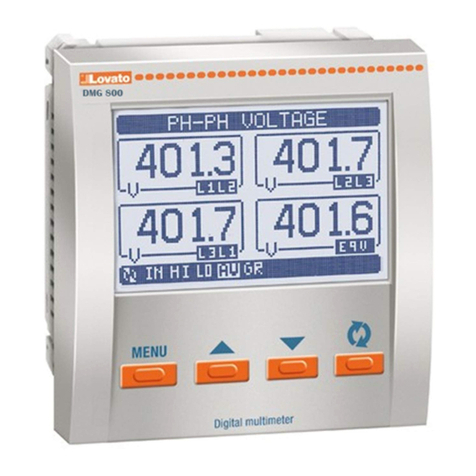
Lovato DMK40 User manual

p. 1 / 25
Doc. code:AHIT303$0500.doc Date: 20/02/2006
77
MULTIMETRO DIGITALE DIGITAL MULTIMETER
DMK40 DMK40
PROTOCOLLO DI COMUNICAZIONE COMMUNICATION PROTOCOL
MODBUS RTU® MODBUS RTU®
ADDENDUM ADDENDUM
I 153 I GB 0206

p. 2 / 25
Doc. code:AHIT303$0500.doc Date: 20/02/2006
INTERFACCIA SERIALE RS-485
Il modello DMK40 è provvisto di una interfaccia seriale RS-485 half duplex optoisolata.
L’impostazione della porta di comunicazione si effettua nel setup del multimetro
tramite alcuni parametri dedicati.
IMPOSTAZIONE DEI PARAMETRI
Premere contemporaneamente il pulsanti C e D per 5 secondi. Sul display 1 apparirà il
parametro P.01. Premere il tasto D sino alla visualizzazione del parametro P.41
indicato nella tabella sottostante.
TABELLA PARAMETRI
PAR Funzione Range Default
P.41 Indirizzo 1 ÷ 255 1
P.42 Baud rate
OFF
1200
2400
4800
9600
19200
9600
P.43 Parità
0 - nessuna parità
1 - parità pari
2 - parità dispari
0
P.44 Protocollo 0 – ASCII
1 - RTU 1
P.45 Modem 0 - no risposta aut.
1 – risposta aut. 0
P46 Bit x byte 0 – 7 bit
1 – 8 bit 1
PROTOCOLLO MODBUS® RTU
Se si seleziona il parametro P.44 come protocollo Modbus® RTU, la struttura del
messaggio di comunicazione è così costituito:
T1
T2
T3
Indirizzo
( 8 bit)
Funzione
(8 bit)
Dati
(N x 8 bit)
CRC
(16 bit)
T1
T2
T3
•il campo Indirizzo contiene l’indirizzo dello strumento slave cui il messaggio viene
inviato.
•il campo Funzione contiene il codice della funzione che deve essere eseguita dallo
slave.
•il campo Dati contiene i dati inviati allo slave o quelli inviati dallo slave come risposta
ad una domanda.
•il campo CRC consente sia al master che allo slave di verificare se ci sono errori di
trasmissione.
Questo consente, in caso di disturbo sulla linea di trasmissione, di ignorare il
messaggio inviato per evitare problemi sia dal lato master che slave.
•la sequenza T1 T2 T3 corrisponde al tempo durante il quale non devono essere
scambiati dati sul bus di comunicazione, per consentire agli strumenti collegati di
riconoscere la fine di un messaggio e l’inizio del successivo. Questo tempo deve
essere pari a 3.5 caratteri.
Il multimetro misura il tempo trascorso tra la ricezione di un carattere e il successivo e
se questo tempo supera quello necessario per trasmettere 3.5 caratteri, riferiti al baud
rate impostato, il prossimo carattere viene considerato l’inizio di un nuovo messaggio.
FUNZIONI MODBUS®
Le funzioni disponibili sono:
04 = Read input
register
Consente la lettura delle
misure disponibili nel
multimetro.
06 = Preset single
register
Permette di modificare i
parametri del setup
07 = Read exception Permette di leggere lo stato
dello strumento
16 = Preset multiple
register
Permette di modificare più
parametri del setup
contemporaneamente
17 = Report slave ID
Permette di leggere
informazioni relative al
multimetro
RS 485 SERIAL INTERFACE
The model DMK40 has a built-in isolated Half duplex RS-485 serial interface.
The communication port setting is obtained through dedicated setup parameters, as
follows.
PARAMETER SETTING
Press keys C and D together for 5 seconds. Display 1 will show parameter P.01. Press
D key to move to parameter P.41, shown on the following table.
PARAMETERS TABLE
PAR Function Range Default
P.41 Address 1 - 255 1
P.42 Baud rate
OFF
1200
2400
4800
9600
19200
9600
P.43 Parity
0 – No parity
1 –even parity
2 – odd parity
0
P.44 Protocol 0 – ASCII
1 - RTU 1
P.45 Modem 0 - no auto response
1 – auto response 0
P46 Bit x byte 0 – 7 bit
1 – 8 bit 1
MODBUS® RTU PROTOCOL
If one selects Modbus® RTU protocol in the parameter P44., the communication
message has the following structure:
T1
T2
T3
Address
( 8 bit)
Function
(8 bit)
Data
(N x 8 bit)
CRC
(16 bit)
T1
T2
T3
•The Address field holds the serial address of the slave destination device.
•The Function field holds the code of the function that must be executed by the slave.
•The Data field contains data sent to the slave or data received from the slave in
response to a query
•The CRC field allows the master and slave devices to check the message integrity. If
a message has been corrupted by electrical noise or interference, the CRC field allows
the devices to recognize the error and thereby to ignore the message.
•The T1 T2 T3 sequence corresponds to a time in which data must not be exchanged
on the communication bus to allow the connected devices to recognize the end of one
message and the beginning of another. This time must be at least 3.5 times the time
required to send one character.
The multimeter measures the time that elapses from the reception of one character
and the following one. If this time exceeds the time necessary to send 3.5 characters
at the selected baud rate, then the next character will be considered as the first of a
new message.
MODBUS® FUNCTIONS
The available functions are:
04 = Read input
register
Allows to read the multimeter
measures.
06 = Preset single
register
Allows to set the setup
parameters
07 = Read exception Allows to read the device
status
16 = Preset multiple
register
Allows to set more than one
parameter at the same time.
17 = Report slave ID
Allows to read information
about the multimeter.

p. 3 / 25
Doc. code:AHIT303$0500.doc Date: 20/02/2006
FUNZIONI
Per esempio, se si vuole leggere dal multimetro con indirizzo 8 il valore della tensione
concatenata equivalente che si trova alla locazione 16 (10 Hex), il messaggio da
spedire è il seguente:
08 04 00 0F 00 02 41 51
Dove:
08 = indirizzo slave.
04 = funzione di lettura locazione.
00 0F = indirizzo della locazione diminuito di un’unità, contenete il valore di tensione
concatenata equivalente.
00 02 = numero di registri da leggere a partire dall’indirizzo 0F.
4151 = checksum CRC.
La risposta del multimetro è la seguente:
08 04 04 00 00 00 64 63 6A
Dove:
08 = indirizzo del multimetro (Slave 08).
04 = funzione richiesta dal Master.
04 = numero di byte inviati dal multimetro.
00 00 00 64 = valore esadecimale della tensione concatenata equivalente 100 V.
63 6A = = checksum CRC.
FUNZIONE 04: READ INPUT REGISTER
La funzione 04 permette di leggere più grandezze consecutive in memoria. Ogni
grandezza è definita come “unsigned long” e quindi occupa 2 registri (4 byte). E’
possibile leggere fino a 30 grandezze consecutive.
L’indirizzo di ciascuna grandezza e’ indicato nella Tabella 2 riportata nelle pagine
seguenti. Come da standard Modbus®, l’indirizzo specificato nel messaggio va
diminuito di 1 rispetto a quello effettivo riportato nella tabella.
Se l’indirizzo richiesto non è compreso nella tabella o il numero di grandezze richieste
è maggiore di 30 il multimetro ritorna un messaggio di errore ( vedi tabella errori).
Richiesta Master:
Indirizzo slave 08h
Funzione 04h
MSB Indirizzo registro 00h
LSB Indirizzo registro 09h
MSB Numero registri 00h
LSB Numero registri 08h
MSB CRC 21h
LSB CRC 57h
Nell’esempio vengono richiesti allo slave numero 8, 8 registri consecutivi a partire
dall’indirizzo 10h.
Quindi vengono letti i registri dall’ 10h al 17h.Il comando termina sempre con il valore
di checksum CRC.
Risposta Slave:
Indirizzo slave 08h
Funzione 04h
Numero di byte 10h
MSB Dato 10h 00h
LSB Dato 10h 00h
--------------------------------------------------- ----
MSB Dato 17h 00h
LSB Dato 17h 00h
MSB CRC 5Eh
LSB CRC 83h
La risposta è composta sempre dall’indirizzo dello slave, dalla funzione richiesta dal
Master e dai dati dei registri richiesti. La risposta termina sempre con il valore di
checksum CRC.
FUNCTIONS
For instance, to read the value of the equivalent phase-to-phase voltage, which
resides at location 16 (10 Hex) of the multimeter with serial address 08, the message
to send is the following:
08 04 00 0F 00 02 41 51
Whereas:
08 = slave address
04 = Modbus® function ‘Read input register’
00 0F = Address of the required register (equivalent phase-to-phase voltage)
decreased by one
00 02 = Number of registers to be read beginning from address 000F
4151 = CRC Checksum
The multimeter answer is the following:
08 04 04 00 00 00 64 63 6A
Whereas:
08 = Multimeter address (Slave 08)
04 = Function requested by the master
04 = Number of bytes sent by the multimeter
00 00 00 64 = Hex value of the equivalent phase-to-phase voltage (100 V)
63 6A = CRC checksum
FUNCTION 04: READ INPUT REGISTER
The Modbus® function 04 allows to read one or more consecutive measures from the
slave memory. In this case, each measure is defined as ‘unsigned long’, so it has a
length of 2 registers (4 bytes). It is possible to read up to 30 consecutive measures.
The address of each measure is given in Table 2 (see following pages). As for
Modbus® standard, the address in the query message must be decreased by one
from the effective address reported in the table.
If the measure address is not included in the table or the number of requested
measures exceeds 30, the multimeter will return an error code (see error table)
Master query:
Slave address 08h
Function 04h
MSB address 00h
LSB address 09h
MSB register number 00h
LSB register number 08h
MSB CRC 21h
LSB CRC 57h
In the above example, slave 08 is requested for 8 consecutive registers beginning with
address 10h.
Thus, registers from 10h to 17h will be returned. As usual, the message ends with the
CRC checksum.
Slave response:
Slave address 08h
Function 04h
Byte number 10h
MSB register 10h 00h
LSB register 10h 00h
--------------------------------------------------- ----
MSB register 17h 00h
LSB register 17h 00h
MSB CRC 5Eh
LSB CRC 83h
The response is always composed of the slave address, the function code requested
by the master and the contents of the requested registers. The answer ends with the
CRC.

p. 4 / 25
Doc. code:AHIT303$0500.doc Date: 20/02/2006
Il multimetro formatta le misure automaticamente con i coefficienti di k (1000) e M
(1000000).
Nel protocollo in esame le grandezze vengono trasferite in base all’unità elencata
nella Tabella 2 e sono tutte composte da 4 byte.
Per i valori di power factor, cosφ, potenze attive e reattive, qualora i valori siano
negativi viene posto a 1 il bit 31.
Per i valori di cosφper indicare se il valore è
capacitivo o induttivo viene posto rispettivamente a 1 o 0 il bit 30.
Se il valore di tensione o corrente sono a zero il valore di power factor e cosφviene
inviato con il bit 29 a 1.
FUNZIONE 06: PRESET SINGLE REGISTER
Tale funzione permette di impostare i parametri del setup.
I parametri di setup modificati vengono automaticamente salvati nella memoria
ritenitiva (eeprom) e qualora il valore impostato non rientri nel valore minimo e
massimo della tabella il multimetro risponderà con un messaggio di errore.
Altresì se viene richiesto un parametro ad un indirizzo inesistente verrà risposto
con un messaggio di errore. L’indirizzo ed il range valido per i vari parametri
può essere trovato nella Tabella 3.
Con la funzione 06 e’ inoltre possibile eseguire dei comandi ( come il reset dei
contatori di energia) utilizzando gli indirizzi ed i valori riportati nella Tabella 4.
Richiesta Master:
Indirizzo slave 08h
Funzione 06h
MSB Indirizzo registro 20h
LSB Indirizzo registro 01h
MSB Dato 00h
LSB Dato 0Ah
MSB CRC 53h
LSB CRC 54h
Nell’esempio viene richiesto di modificare il registro 2 (rapporto TA) con il
valore 10 (il valore 10 corrisponde a 1.0).
Risposta Slave:
La risposta è un eco della domanda, cioè viene inviato al master l’indirizzo del dato da
modificare e il nuovo valore del parametro.
FUNZIONE 07: READ EXCEPTION STATUS
Tale funzione permette di leggere lo stato in cui si trova lo strumento.
Richiesta Master:
Indirizzo slave 08h
Funzione 07h
MSB CRC 47h
LSB CRC B2h
La tabella seguente riporta il significato del byte inviato dal multimetro come risposta:
BIT SIGNIFICATO
0 Funzionamento normale
1 Setup base abilitato
2 Setup esteso abilitato
The multimeter automatically formats the measures with the coefficient of k (1000) and
M (1000000).
The measures transferred by the protocol are expressed in the unit of measure listed
in Table 2, and they are all 4 byte long.
For power factor, cosφ, active and reactive power reading, when the values are
negative, the 31st bit of the value is set to 1.
For cosφvalues, to indicate capacitive or inductive, the 30th bit is set
respectively to 1 or 0.
If voltage or current value is 0, then power factor and cosφvalues are transmitted with
the 29th bit set to 1.
FUNCTION 06: PRESET SINGLE REGISTER
This function allows to set the setup parameters.
Modified parameters are automatically saved in the non-volatile EEPROM
memory. If the value is not in the correct range, the multimeter will answer with
an error message. In the same way, if the parameter address is not recognised,
the multimeter will send an error response.
The address and the valid range for each parameter are indicated in Table 3.
With function 06, some commands (like the energy meters reset) can be
possibly executed sending the addresses and the values given in Table 4.
Master message:
Slave address 08h
Function 06h
MSB register address 20h
LSB register address 01h
MSB data 00h
LSB data 0Ah
MSB CRC 53h
LSB CRC 54h
In the above message, the master wants to set the register 2 (CT ratio) to a value
of 10 (i.e. 1.0).
Slave response:
The slave response is an echo to the query that is the slave sends back to the master
the address and the new value of the variable.
FUNCTION 07: READ EXCEPTION STATUS
This function allows to read the status of the instrument.
Master query:
Slave address 08h
Function 07h
MSB CRC 47h
LSB CRC B2h
The following table gives the meaning of the status byte sent by the multimeter as
answer:
BIT MEANING
0 Normal operation
1 Basic setup enabled
2 Advanced setup enabled

p. 5 / 25
Doc. code:AHIT303$0500.doc Date: 20/02/2006
FUNZIONE 16: PRESET MULTIPLE REGISTER
Questa funzione permette di modificare più parametri consecutivamente o parametri
composti da più di 2 byte. L’indirizzo ed il range valido per i vari parametri possono
essere trovato nella Tabella 3.
Nell’esempio viene richiesta la modifica del parametro rapporto TA e TV
rispettivamente al valore 50.0 e 166.7.
Richiesta Master:
Indirizzo slave 08h
Funzione 10h
MSB Indirizzo registro 20h
LSB Indirizzo registro 01h
MSB Numero registri 00h
LSB Numero registri 02h
MSB Dato 01h
LSB Dato F4h
MSB Dato 06h
LSB Dato 83h
MSB CRC 55h
LSB CRC 3Ah
Risposta Slave:
Indirizzo slave 08h
Funzione 10h
MSB Indirizzo registro 20h
LSB Indirizzo registro 01h
MSB Numero byte 00h
LSB Numero byte 04h
MSB CRC 9Bh
LSB CRC 53h
FUNZIONE 17: REPORT SLAVE ID
Questa funzione permette di identificare il tipo di strumento.
Richiesta Master.
Indirizzo slave 08h
Funzione 11h
MSB CRC C6h
LSB CRC 7Ch
Risposta Slave:
Indirizzo slave 08h
Funzione 11h
Numero byte 04h
Dato 1 (Modello multimetro) 20h
Dato 2 (Revisione software) 00h
Dato 3 (Checksum) 1Eh
Dato 4 (Checksum) B1h
MSB CRC 3Bh
LSB CRC 55h
Il Dato 1 rappresenta il modello del multimetro, mentre il Dato 2 la revisione del
software. l Dato 3 e 4 rappresentano il checksum.
FUNCTION 16: PRESET MULTIPLE REGISTER
This function allows to modify multiple parameters with a single message, or to preset
a value longer than one register. The address and the valid range for each parameter
are stated in Table 3.
In the following example, the master requests to modify the CT and VT ratios together,
respectively to a value of 50.0 and 166.7.
Master message:
Slave address 08h
Function 10h
MSB register address 20h
LSB register address 01h
MSB register number 00h
LSB register number 02h
MSB data 01h
LSB data F4h
MSB data 06h
LSB data 83h
MSB CRC 57h
LSB CRC 22h
Slave response:
Slave address 08h
Function 10h
MSB register address 20h
LSB register address 01h
MSB byte number 00h
LSB byte number 04h
MSB CRC 9Bh
LSB CRC 53h
FUNCTION 17: SLAVE ID REPORT
This function allows to identify the type of instrument.
Master query.
Slave address 08h
Function 11h
MSB CRC C6h
LSB CRC 7Ch
Slave response:
Slave address 08h
Function 11h
Byte number 04h
Data 1 (Type of multimeter) 20h
Data 2 (Software revision) 00h
Data 3 (Checksum) 1Eh
Data 4 (Checksum) B1h
MSB CRC 3Bh
LSB CRC 55h
Data 1 represents the multimeter type while Data 2 holds the software revision.
Data 3 and 4 represent checksum values.

p. 6 / 25
Doc. code:AHIT303$0500.doc Date: 20/02/2006
FUNZIONE 23: Read/Write 4X Registers)
Questa funzione permette di combinare lettura e scrittura in un unico comando.
E’ possibile leggere un gruppo di registri e scrivere un altro diverso gruppo.
Richiesta Master:
Indirizzo slave 08h
Funzione 17h
Legge MSB Indirizzo registro 30h
Legge LSB Indirizzo registro 01h
MSB Numero registri da leggere 00h
LSB Numero registri da leggere 04h
Scrive MSB Indirizzo registro 2Fh
Scrive LSB Indirizzo registro FFh
MSB Numero registri da scrivere 00h
LSB Numero registri da scrivere 01h
Numero di Bytes 02h
Scirve dato 1 MSB 00h
Scrive dato 1 LSB 01h
MSB CRC 90h
LSB CRC 2Ch
Risposta Slave:
Indirizzo slave 08h
Funzione 17h
Numero byte 04h
Dato 1 20h
Dato 2 00h
Dato 3 1Eh
Dato 4 B1h
MSB CRC 3Bh
LSB CRC 55h
La risposta è composta sempre dall’indirizzo dello slave, dalla funzione richiesta dal
Master e dai dati dei registri richiesti. La risposta termina sempre con il valore di
checksum CRC.
La funzione 23 viene utilizzata solo per impostare il record all’ indirizzo 3002h e
per leggere i dati del record dall’indirizzo 3100h. Con il resto degli indirizzi
questa funzione non è utilizzata. Questa funzione è stata implementata per
aumentare le prestazioni di trasferimento dei record.
TABELLA ERRORI
Nella seguente tabella vengono riportati i codici di errore inviati dallo slave al
master.
01 Funzione non valida
02 Indirizzo registro illegale
03 Valore del parametro di setup fuori range
04 Formato variabile non valido
FUNCTION 23: Read/Write 4X Registers
This function allows to combine reading and writing all in one command.
It is possible to read a set of registers and write another different set.
Master query:
Slave address 08h
Function 17h
Read MSB register address 30h
Read LSB register address 01h
MSB number of registers to read 00h
LSB number of registers to read 04h
Write MSB register address 2Fh
Write LSB register address FFh
MSB number of registers to read 00h
LSB number of registers to read 01h
Number of Bytes 02h
Write Data 1 MSB 00h
Write Data 1 LSB 01h
MSB CRC 90h
LSB CRC 2Ch
Slave response:
Slave address 08h
Function 17h
Number of byte 04h
Data 1 20h
Data 2 00h
Data 3 1Eh
Data 4 B1h
MSB CRC 3Bh
LSB CRC 55h
The response is always composed by the slave address, the Master query function
and the data of the required registers. The response always ends with a checksum
value CRC.
Function 23 is only used to set the record at the 3002h address and to read the record
data at the 3100h address. This function is not used with the remaining addresses. It
has been implemented to increase the record transfer performance.
ERROR TABLE
The following table shows the error codes that the slave returns in case of
invalid queries.
01 Invalid function
02 Invalid register address
03 Parameter value out of bounds
04 Invalid variable format

p. 7 / 25
Doc. code:AHIT303$0500.doc Date: 20/02/2006
PROTOCOLLO MODBUS® ASCII
Se si seleziona il parametro P.44 come protocollo Modbus® ASCII, la struttura del
messaggio di comunicazione è così costituito:
:
Indirizzo
(2 chars)
Funzione
(2 chars)
Dati
(N chars)
LRC
(2 chars)
CR
LF
•il campo Indirizzo contiene l’indirizzo dello strumento slave cui il messaggio viene inviato.
•il campo Funzione contiene il codice della funzione che deve essere eseguita dallo slave.
•il campo Dati contiene i dati inviati allo slave o quelli inviati dallo slave come risposta
ad una domanda.
•il campo LRC consente sia al master che allo slave di verificare se ci sono errori di
trasmissione.
Questo consente, in caso di disturbo sulla linea di trasmissione, di ignorare il
messaggio inviato per evitare problemi sia dal lato master che slave.
• Il messaggio termina sempre con i caratteri di controllo CRLF (0D 0A).
FUNZIONI MODBUS®
Le funzioni disponibili sono:
04 = Read input
register
Consente la lettura delle
misure disponibili nel
multimetro.
06 = Preset single
register
Permette di modificare i
parametri del setup
07 = Read exception Permette di leggere lo stato
dello strumento
16 = Preset multiple
register
Permette di modificare più
parametri del setup
contemporaneamente
17 = Report slave ID
Permette di leggere
informazioni relative al
multimetro
Esempio:
Per esempio, se si vuole leggere dal multimetro con indirizzo 8 il valore
della tensione concatenata equivalente che si trova alla locazione 16
(10 Hex), il messaggio da spedire è il seguente:
: 0 8 0 4 0 0 0 F 0 0 02 E 3 CRLF
Dove:
08 = indirizzo slave.
04 = funzione di lettura locazione.
00 0F = indirizzo della locazione diminuito di un’unità, contenente il valore di tensione
concatenata equivalente.
00 02 = numero di registri da leggere a partire dall’indirizzo 0F.
E3 = checksum LRC.
La risposta del multimetro è la seguente:
: 0 8 0 4 0 4 0 0 0 0 0 1 A 0 4 F CRLF
Dove:
08 = indirizzo del multimetro (Slave 08).
04 = funzione richiesta dal Master.
04 = numero di byte inviati dal multimetro.
00 00 01 A0 = valore esadecimale della tensione concatenata equivalente 416 V.
4F = checksum LRC.
FUNZIONE 04: READ INPUT REGISTER
La funzione 04 permette di leggere più grandezze consecutive in memoria. Ogni
grandezza è definita come “unsigned long” e quindi occupa 2 registri (4 byte). E’
possibile leggere fino a 14 grandezze consecutive.
L’indirizzo di ciascuna grandezza e’ indicato nella Tabella 2 riportata nelle pagine
seguenti. Come da standard Modbus®, l’indirizzo specificato nel messaggio va
diminuito di 1 rispetto a quello effettivo riportato nella tabella.
Se l’indirizzo richiesto non è compreso nella tabella o il numero di grandezze richieste
è maggiore di 14 il multimetro ritorna un messaggio di errore ( vedi tabella errori).
MODBUS® ASCII PROTOCOL
If one selects Modbus® ASCII protocol at parameter P.44, the communication
message has the following structure:
:
Address
(2 chars)
Function
(2 chars)
Data
(N chars)
LRC
(2 chars)
CR
LF
•The Address field holds the serial address of the slave destination device.
•The Function field holds the code of the function that must be executed by the slave.
•The Data field contains data sent to the slave or data received from the slave in
response to a query.
•The LRC field allows the master and slave devices to check the message integrity.
If a message has been corrupted by electrical noise or interference, the LRC field
allows the devices to recognize the error and thereby ignore the message.
• The message terminates always with CRLF control character (0D 0A).
MODBUS® FUNCTIONS
The available functions are:
04 = Read input
register
Allows to read the multimeter
measures.
06 = Preset single
register
Allows to set the setup
parameters
07 = Read exception Allows to read the device
status
16 = Preset multiple
register
Allows to set more than one
parameter at the same time.
17 = Report slave ID Allows to read information
about the multimeter.
Example:
For instance, to read the value of the equivalent phase-to-phase
voltage, which resides at location 16 (10 Hex) from the multimeter with
serial address 08, the message to send is the following:
: 0 8 0 4 0 0 0 F 0 0 02 E 3 CRLF
Whereas:
08 = Slave address
04 = Modbus® function ‘Read input register’
00 0F = Address of the required register (equivalent phase-to-phase voltage)
decreased by one
00 02 = Number of registers to be read beginning from address 0F
E3 = LRC Checksum
The multimeter answer is the following:
: 0 8 0 4 0 4 0 0 0 0 0 1 A 0 4 F CRLF
Whereas:
08 = Multimeter address (Slave 08)
04 = Function requested by the master
04 = Number of bytes sent by the multimeter
00 00 01 A0 = Hex value of the equivalent phase-to-phase voltage (416 V)
4F = LRC checksum
FUNCTION 04: READ INPUT REGISTER
The Modbus® function 04 allows to read one or more consecutive measures from the
slave memory. In this case, each measure is defined as ‘unsigned long’, so it has a
length of 2 registers (4 bytes). It is possible to read up to 14 consecutive measures.
The address of each measure is given in Table 2 (see following pages). As for
Modbus® standard, the address in the query message must be decreased by one
from the effective address reported in the table.
If the measure address is not included in the table or the number of requested
measures exceeds 14, the multimeter will return an error code (see error table).

p. 8 / 25
Doc. code:AHIT303$0500.doc Date: 20/02/2006
Richiesta Master:
:
Indirizzo slave 0 8
Funzione 0 4
MSB Indirizzo registro 0 0
LSB Indirizzo registro 0 9
MSB Numero registri 0 0
LSB Numero registri 0 8
LRC 5 7
CRLF
Nell’esempio vengono richiesti allo slave numero 8, 8 registri consecutivi a partire
dall’indirizzo 10h.
Quindi vengono letti i registri dall’ 10h al 17h.Il comando termina sempre con il valore
di checksum LRC.
Risposta Slave:
:
Indirizzo slave 0 8
Funzione 0 4
Numero di byte 1 0
MSB Dato 10h 0 0
LSB Dato 10h 0 0
--------------------------------------------------- ----
MSB Dato 17h 0 0
LSB Dato 17h 0 0
LRC 8 3
CRLF
La risposta è composta sempre dall’indirizzo dello slave, dalla funzione richiesta dal
Master e dai dati dei registri richiesti. La risposta termina sempre con il valore di
checksum LRC. Il multimetro formatta le misure automaticamente con i coefficienti di
k (1000) e M (1000000).
Nel protocollo in esame le grandezze vengono trasferite in base all’unità elencata
nella Tabella 2 e sono tutte composte da 4 byte.
Per i valori di power factor, cosφ,potenze attive e reattive, qualora i valori siano
negativi viene posto a 1 il bit 31.
Per i valori di cosφper indicare se il valore è capacitivo o induttivo viene posto
rispettivamente a 1 o 0 il bit 30.
Se il valore di tensione o corrente sono a zero il valore di power factor e cosφviene
inviato con il bit 29 a 1.
FUNZIONE 06: PRESET SINGLE REGISTER
Tale funzione permette di impostare i parametri del setup. I parametri di setup
modificati vengono
automaticamente salvati nella memoria ritenitiva (eeprom) e qualora il valore
impostato non rientri nel valore minimo e massimo della tabella il multimetro
risponderà con un messaggio di errore. Altresì se viene richiesto un parametro ad un
indirizzo inesistente verrà risposto con un messaggio di errore. L’indirizzo ed il range
valido per i vari parametri può essere trovato nella Tabella 3.
Con la funzione 06 e’ inoltre possibile eseguire dei comandi ( come il reset dei
contatori di energia) utilizzando gli indirizzi ed i valori riportati nella Tabella 4.
Richiesta Master:
:
Indirizzo slave 0 8
Funzione 0 6
MSB Indirizzo registro 2 0
LSB Indirizzo registro 0 1
MSB Dato 0 0
LSB Dato 0 A
LRC C 7
CRLF
Nell’esempio viene richiesto di modificare il registro 2 (rapporto TA) con il
valore 10 (il valore 10 corrisponde a 1.0).
Master query:
:
Slave address 0 8
Function 0 4
MSB register address 0 0
LSB register address 0 9
MSB register number 0 0
LSB register number 0 8
LRC 5 7
CRLF
In the above example, slave 08 is requested for 8 consecutive registers beginning with
address 10h.
Thus, registers from 10h to 17h will be returned. As usual, the message ends with the
LRC checksum.
Slave response:
:
Slave address 0 8
Function 0 4
Byte number 1 0
MSB Data 10h 0 0
LSB Data 10h 0 0
--------------------------------------------------- ----
MSB Data 17h 0 0
LSB Data 17h 0 0
LRC 8 3
CRLF
The response is always composed of the slave address, the function code requested
by the master and the contents of the requested registers. The answer ends with the
LRC. The multimeter automatically formats the measures with the coefficient of k
(1000) and M (1000000).
The measures transferred by the protocol are expressed in the unit of measure listed
in Table 2, and they are all 4 byte long.
For power factor, cosφ, active and reactive power readings, when the values are
negative, the 31st bit of the value is set to 1.
For cosφvalues, to indicate capacitive or inductive, the 30th bit is set
respectively to 1 or 0.
If the voltage or current value is 0, then power factor and cosφvalues are transmitted
with the 29th bit set to 1.
FUNCTION 06: PRESET SINGLE REGISTER
This function allows to set the setup parameters.
Modified parameters are automatically saved in the non-volatile EEPROM memory. If
the value is not in the correct range, the multimeter will answer with an error message.
In the same way, if the parameter address is not recognised, the multimeter will send
an error response.
The address and the valid range for each parameter are indicated in Table 3.
With function 06, some commands (like the energy meters reset) can be possibly
executed using the addresses and the values given in Table 4.
Master query:
:
Slave Address 0 8
Function 0 6
MSB register address 2 0
LSB register address 0 1
MSB Data 0 0
LSB Data 0 A
LRC C 7
CRLF
In the above message, the master wants to set register 2 (CT ratio) to a value of
10 (i.e. 1.0).

p. 9 / 25
Doc. code:AHIT303$0500.doc Date: 20/02/2006
Risposta Slave:
La risposta è un eco della domanda, cioè viene inviato al master l’indirizzo del dato da
modificare e il nuovo valore del parametro.
FUNZIONE 07: READ EXCEPTION STATUS
Tale funzione permette di leggere lo stato in cui si trova lo strumento.
Richiesta Master:
:
Indirizzo slave 0 8
Funzione 0 7
LRC F 1
CRLF
La tabella seguente riporta il significato del byte inviato dal multimetro come risposta:
BIT SIGNIFICATO
0 Funzionamento normale
1 Setup base abilitato
2 Setup esteso abilitato
FUNZIONE 16: PRESET MULTIPLE REGISTER
Questa funzione permette di modificare più parametri consecutivamente o parametri
composti da più di 2 byte. L’indirizzo ed il range valido per i vari parametri possono
essere trovato nella Tabella 3.
Nell’esempio viene richiesta la modifica del parametro rapporto TA e TV
rispettivamente al valore 50.0 e 166.7.
Richiesta Master:
:
Indirizzo slave 0 8
Funzione 1 0
MSB Indirizzo registro 2 0
LSB Indirizzo registro 0 1
MSB Numero registri 0 0
LSB Numero registri 0 2
MSB Dato 0 1
LSB Dato F 4
MSB Dato 0 6
LSB Dato 8 3
LRC 4 7
CRLF
Risposta Slave:
:
Indirizzo slave 0 8
Funzione 1 0
MSB Indirizzo registro 2 0
LSB Indirizzo registro 0 2
MSB Numero byte 0 0
LSB Numero byte 0 4
LRC C 2
CRLF
Slave response:
The slave response is an echo to the query that is the slave sends back to the master
the address and the new value of the variable.
FUNCTION 07: READ EXCEPTION STATUS
This function allows to read the status of the instrument.
Master query:
:
Slave Address 0 8
Function 0 7
LRC F 1
CRLF
The following table gives the meaning of the status byte sent by the multimeter as
answer:
BIT MEANING
0 Normal operation
1 Basic setup enabled
2 Advanced setup enabled
FUNCTION 16: PRESET MULTIPLE REGISTER
This function allows to modify multiple parameters, with a single message, or to preset
a value longer than one register. The address and the valid range for each parameter
are stated in Table 3.
In the following example, the master requests to modify the CT and VT ratios together,
respectively to value 50.0 and 166.7.
Master query:
:
Slave Address 0 8
Function 1 0
MSB register address 2 0
LSB register address 0 1
MSB register number 0 0
LSB register number 0 2
MSB Data 0 1
LSB Data F 4
MSB Data 0 6
LSB Data 8 3
LRC 4 7
CRLF
Slave response:
:
Slave Address 0 8
Function 1 0
MSB register address 2 0
LSB register address 0 2
MSB byte number 0 0
LSB byte number 0 4
LRC C 2
CRLF

p. 10 / 25
Doc. code:AHIT303$0500.doc Date: 20/02/2006
FUNZIONE 17: REPORT SLAVE ID
Questa funzione permette di identificare il tipo di strumento.
Richiesta Master.
:
Indirizzo slave 0 8
Funzione 1 1
LRC C 6
CRLF
Risposta Slave:
:
Indirizzo slave 0 8
Funzione 1 1
Numero byte 0 4
Dato 1 2 0
Dato 2 2 8
Dato 3 2 1
Dato 4 2 B
LRC 4 F
CRLF
Il Dato 1 rappresenta il modello del multimetro, mentre il Dato 2 la revisione del
software.Il Dato 3 e 4 rappresentano il checksum.
FUNZIONE 23: Read/Write 4X Registers
Questa funzione permette di combinare lettura e scrittura in un unico comando.
E’ possibile leggere un gruppo di registri e scrivere un altro diverso gruppo.
Richiesta Master:
:
Indirizzo slave 0 8
Funzione 1 1
Legge MSB Indirizzo registro 1 E
Legge LSB Indirizzo registro 0 1
MSB Numero registri da leggere 0 0
LSB Numero registri da leggere 0 4
Scrive MSB Indirizzo registro 2 F
Scrive LSB Indirizzo registro F F
MSB Numero registri da scrivere 0 0
LSB Numero registri da scrivere 0 1
Numero di Bytes 0 2
Scirve dato 1 MSB 0 0
Scrive dato 1 LSB 0 1
LRC 7 A
CRLF
Risposta Slave:
:
Indirizzo slave 0 8
Funzione 1 1
Numero byte 0 4
Dato 1 1 4
Dato 2 0 0
Dato 3 1 E
Dato 4 B 1
LRC E E
CRLF
La risposta è composta sempre dall’indirizzo dello slave, dalla funzione richiesta dal
Master e dai dati dei registri richiesti. La risposta termina sempre con il valore di
checksum CRC.
FUNCTION 17: SLAVE ID REPORT
This function allows to identify the instrument type.
Master query:
:
Slave Address 0 8
Function 1 1
LRC C 6
CRLF
Slave response:
:
Slave Address 0 8
Function 1 1
Byte number 0 4
Data 1 2 0
Data 2 2 8
Data 3 2 1
Data 4 2 B
LRC 4 F
CRLF
Data 1 represents the multimeter type while Data 2 the software revision.
Data 3 and 4 represent checksum.
FUNCTION 23: Read/Write 4X Registers
This function allows to combine both reading and writing all in one command.
It is possible to read one set of registers and write another different set.
Master query:
:
Slave address 0 8
Function 1 1
Read MSB register address 1 E
Read LSB register address 0 1
MSB Number of registers to read 0 0
LSB Number of registers to read 0 4
Write MSB register address 2 F
Write LSB register address F F
MSB Number of registers to write 0 0
LSB Number of registers to write 0 1
Number of Bytes 0 2
Write data 1 MSB 0 0
Write data 1 LSB 0 1
LRC 7 A
CRLF
Slave response:
:
Slave address 0 8
Function 1 1
Number of byte 0 4
Data 1 1 4
Data 2 0 0
Data 3 1 E
Data 4 B 1
LRC E E
CRLF
The response is always composed by the slave address, the Master query function
and the data of the required registers. The response always ends with a checksum
value CRC.

p. 11 / 25
Doc. code:AHIT303$0500.doc Date: 20/02/2006
Algoritmo di calcolo del CRC
CRC calculation algorithm
CALCOLO DEL CRC (CHECKSUM)
Esempio di calcolo:
Frame = 0207h
Inizializzazione CRC 1111 1111 1111 1111
Carica primo byte 0000 0010
Esegue xor con il primo 1111 1111 1111 1101
Byte della frame
Esegue primo shift a dx 0111 1111 1111 1110 1
Carry=1,carica polinomio 1010 0000 0000 0001
Esegue xor con il 1101 1111 1111 1111
polinomio
Esegue secondo shift dx 0110 1111 1111 1111 1
Carry=1,carica polinomio 1010 0000 0000 0001
Esegue xor con il 1100 1111 1111 1110
polinomio
Esegue terzo shift 0110 0111 1111 1111 0
Esegue quarto shift 0011 0011 1111 1111 1
Carry=1, carica polinomio 1010 0000 0000 0001
Esegue xor con il 1001 0011 1111 1110
Polinomio
Eseque quinto shift dx 0100 1001 1111 1111 0
Eseque sesto shift dx 0010 0100 1111 1111 1
Carry=1, carica polinomio 1010 0000 0000 0001
Esegue xor con polinomio 1000 0100 1111 1110
Esegue settimo shift dx 0100 0010 0111 1111 0
Esegue ottavo shift dx 0010 0001 0011 1111 1
Carry=1, carica polinomio 1010 0000 0000 0001
Carica secondo byte 0000 0111
della frame
Esegue xor con il 1000 0001 0011 1001
Secondo byte della frame
Esegue primo shift dx 0100 0000 1001 1100 1
Carry=1, carica polinomio 1010 0000 0000 0001
Esegue xor con il 1110 0000 1001 1101
polinomio
Esegue secondo shift dx 0111 0000 0100 1110 1
Carry=1, carica polinomio 1010 0000 0000 0001
Esegue xor con il 1101 0000 0100 1111
polinomio
Esegue terzo shift dx 0110 1000 0010 0111 1
Carry=1, carica polinomio 1010 0000 0000 0001
Esegue xor con il 1100 1000 0010 0110
polinomio
Esegue quarto shift dx 0110 0100 0001 0011 0
Esegue quinto shift dx 0010 0100 0000 1001 1
Carry=1, carica polinomio 1010 0000 0000 0001
Esegue xor con il 1001 0010 0000 1000
polinomio
Esegue sesto shift dx 0100 1001 0000 0100 0
Esegue settimo shift dx 0010 0100 1000 0010 0
Esegue ottavo shift dx 0001 0010 0100 0001 0
Risultato CRC 0001 0010 0100 0001
12h 41h
Nota: Il byte 41h viene spedito per primo
(anche se e’ il LSB), poi viene trasmesso 12h.
CALCOLO DEL LRC (CHECKSUM)
Esempio di calcolo:
Indirizzo 0 1 00000001
Funzione 0 4 00000100
Start address hi. 0 0 00000000
Start address lo. 0 0 00000000
Numero registri 0 8 00001000
Somma 00001101
1° Complemento 11110010
+ 1 00000001
2° Complemento 11110011
Risultato LRC F3
CRC CALCULATION (CHECKSUM)
Example of CRC calculation:
Frame = 0207h
CRC initialization 1111 1111 1111 1111
Load the first byte 0000 0010
Execute xor with the first 1111 1111 1111 1101
Byte of the frame
Execute 1st right shift 0111 1111 1111 1110 1
Carry=1,load polynomial 1010 0000 0000 0001
Execute xor with the 1101 1111 1111 1111
polynomial
Execute 2nd right shift 0110 1111 1111 1111 1
Carry=1,load polynomial 1010 0000 0000 0001
Execute xor with the 1100 1111 1111 1110
polynomial
Execute 3rd right shift 0110 0111 1111 1111 0
Execute 4th right shift 0011 0011 1111 1111 1
Carry=1,load polynomial 1010 0000 0000 0001
Execute xor with the 1001 0011 1111 1110
polynomial
Execute 5th right shift 0100 1001 1111 1111 0
Execute 6th right shift 0010 0100 1111 1111 1
Carry=1,load polynomial 1010 0000 0000 0001
Execute xor with the 1000 0100 1111 1110
polynomial
Execute 7th right shift 0100 0010 0111 1111 0
Execute 8th right shift 0010 0001 0011 1111 1
Carry=1,load polynomial 1010 0000 0000 0001
Load the second byte 0000 0111
of the frame
Execute xor with the 1000 0001 0011 1001
Second byte of the frame
Execute 1st right shift 0100 0000 1001 1100 1
Carry=1,load polynomial 1010 0000 0000 0001
Execute xor with the 1110 0000 1001 1101
polynomial
Execute 2nd right shift 0111 0000 0100 1110 1
Carry=1,load polynomial 1010 0000 0000 0001
Execute xor with the 1101 0000 0100 1111
polynomial
Execute 3rd right shift 0110 1000 0010 0111 1
Carry=1,load polynomial 1010 0000 0000 0001
Execute xor with the 1100 1000 0010 0110
polynomial
Execute 4th right shift 0110 0100 0001 0011 0
Execute 5th right shift 0010 0100 0000 1001 1
Carry=1,load polynomial 1010 0000 0000 0001
Execute xor with the 1001 0010 0000 1000
polynomial
Execute 6th right shift 0100 1001 0000 0100 0
Execute 7th right shift 0010 0100 1000 0010 0
Execute 8th right shift 0001 0010 0100 0001 0
CRC Result 0001 0010 0100 0001
12h 41h
Note: The byte 41h is sent first (even if it
is the LSB), then 12h is sent.
LRC CALCULATION (CHECKSUM)
Example of LRC calculation:
Address 0 1 00000001
Function 0 4 00000100
Start address hi. 0 0 00000000
Start address lo. 0 0 00000000
Number of registers 0 8 00001000
Sum 00001101
1° complement 11110010
+ 1 00000001
2° complement 11110011
Result LRC F3
CRC xor BYTE = CRC
n = 0
CRC right shift
carry over
CRC xor POLY = CRC
n = n + 1
next BYTE
end message
End
n > 7
Hex FFFF = CRC
no
no
yes
yes

p. 12 / 25
Doc. code:AHIT303$0500.doc Date: 20/02/2006
SETUP SISTEMA ACQUISIZIONE DATI
IMPOSTAZIONE DMK40
Il DMK40 viene prodotto con parametri di default che disabilitano il data-
logger. L’abilitazione del data-logger può essere facilmente effettuata
mediante il software Lovato o altro software di controllo tramite protocollo di
comunicazione MODBUS. L’attivazione del data-logger tramite MODBUS
RTU comporta l’impostazione dei seguenti parametri:
1. Impostare anno orologio datario all’indirizzo 2150h.
2. Impostare mese orologio datario all’indirizzo 2152h.
3. Impostare giorno orologio datario all’indirizzo 2154h.
4. Impostare ora orologio datario all’indirizzo 2156h.
5. Impostare minuti orologio datario all’indirizzo 2158h.
6. Impostare secondi orologio datario all’indirizzo 215Ah.
7. Impostare il tempo campionamento in ore all’indirizzo 215Ch.
8. Impostare il tempo campionamento in minuti all’indirizzo 215Eh.
9. Impostare il tempo campionamento in secondi all’indirizzo 2160h.
10. Impostare le misure da acquisire dall’ indirizzo 2162h all’ indirizzo
21A0h (massimo 32 misure). Il valore inviato a questi indirizzi deve
essere compreso nell’ intervallo tra 1 e 238 della tabella 2.
11. Salvare le impostazioni eseguite inviando il valore 1 all’indirizzo 2406h.
12. Una volta eseguite le impostazioni sopradescritte il sistema di
acquisizione viene automaticamente avviato. Quando si vuole fermare
o riavviare il sistema di acquisizione dati è necessario inviare il valore 1
o 0 all’indirizzo 2602h.
DOWNLOAD DEI DATI
Il trasferimento dei dati dal data-logger del DMK40 a PC può essere
facilmente effettuato mediante il software Lovato o altro software di controllo
tramite protocollo di comunicazione MODBUS. Il trasferimento dei dati da
DMK40 a PC tramite protocollo MODBUS, comporta l’esecuzione della
seguente procedura:
1. Leggere all’indirizzo 3000h il numero di record memorizzati.
2. Settare all’indirizzo 3002h il record da ricevere.
3. Leggere I valori del record in base a come è stato settato il sistema di
acquisizione. I valori richiesti dall’ indirizzo 3100h all’indirizzo 310Ah
rappresentano la data e ora in cui il record è stato memorizzato. In base
al numero di misure settate nel sistema di acquisizione leggere le
misure del record richiesto a partire dall’ indirizzo 310Ch. Il buffer della
porta seriale è di 300 caratteri utili contenere il record completo con
data , ora e 32 misure (sia con Modbus® RTU o ASCII).
Per velocizzare la richiesta di un record è indispensabile utilizzare la funzione
Modbus 23. Questa funzione permette di settare il record da trasferire e
leggere il numero di byte del record.
DATA-LOGGER SYSTEM SETUP
DMK40 SETTING
The DMK40 is supplied with default parameters that disable the data-logger.
Enabling the data-logger is easily obtained through the Lovato or other
control software using Modbuscommunication protocol. The activation of
the data-logger by the ModbusRTU is obtained by setting the following
parameters:
1. Set the year time clock to the 2150h address.
2. Set the month time clock to the 2152h address.
3. Set the day time clock to the 2154h address.
4. Set the hours time clock to the 2156h address.
5. Set the minutes time clock to the 2158h address.
6. Set the seconds time clock to the 215Ah address.
7. Set the time sampling in hours to the 215Ch address.
8. Set the time sampling in minutes to the 215Eh address.
9. Set the time sampling in seconds to the 2160h address.
10. Set the measurement acquisition to the addresses from 2162h to 214A0h
(32 measurements maximum). The value sent to these addresses must
be included in the interval between 1 and 238 of Table 2.
11. Save the settings made by sending the value 1 to the 2406h address.
12. Once the above-stated settings have been made, the acquisition
system will automatically begin. When the data acquisition system must
be stopped or restarted, the value 1 or 0 must be respectively sent to
the 2602h address.
DATA DOWNLOAD
The data download from the DMK40 data-logger to PC can be easily
achieved by using the Lovato or other control software with the Modbus
communication protocol. The data download from the DKM40 to PC by
Modbusprotocol can be obtained with the following procedure:
1. Read the number of stored records at the 3000h address.
2. Set the record in response at the 3002h address.
3. Read the values of the record according to the way the acquisition system
has been set. The values required from the 3100h address to the 310Ah
address represent the date and time the record was stored. According to
the number of measurements set in the acquisition system, read the
measurement of the required record by starting with the 310Ch address.
The serial port buffer consists of 300 characters sufficient to hold the
complete record with date, time and 32 measurements (either with
Modbus® RTU or ASCII).
To speed up the record query, it is essential to use the Modbusfunction 23.
This function consents to set the record to be downloaded and read the
number of byte of the record.

p. 13 / 25
Doc. code:AHIT303$0500.doc Date: 20/02/2006
TABELLA 2: TABLE 2:
MISURE FORNITE DAL PROTOCOLLO DI COMUNNICAZIONE MEASURES SUPPLIED BY SERIAL COMMUNICATION PROTOCOL
Nr.
No.
INDIRIZZO
ADDRESS
WORDS MISURA MEASURE UNITA’
UNIT
FORMATO
FORMAT
1 02h 2 Tensione di fase L1 L1 Phase voltage V Unsigned long
2 04h 2 Tensione di fase L2 L2 Phase voltage V Unsigned long
3 06h 2 Tensione di fase L3 L3 Phase voltage V Unsigned long
4 08h 2 Tensione di fase equivalente Total phase voltage V Unsigned long
5 0ah 2 Tensione concatenata L1-L2 L1-L2 phase-to-phase voltage V Unsigned long
6 0ch 2 Tensione concatenata L2-L3 L2-L3 phase-to-phase voltage V Unsigned long
7 0eh 2 Tensione concatenata L3-L1 L3-L1 phase-to-phase voltage V Unsigned long
8 10h 2 Tensione di linea equivalente Equivalent line voltage V Unsigned long
9 12h 2 Corrente di fase L1 L1 Phase current A / 100 Unsigned long
10 14h 2 Corrente di fase L2 L2 Phase current A / 100 Unsigned long
11 16h 2 Corrente di fase L3 L3 Phase current A / 100 Unsigned long
12 18h 2 Corrente equivalente Equivalent current A / 100 Unsigned long
13 1Ah 2 Potenza attiva equivalente Total active power W Unsigned long
14 1Ch 2 Potenza reattiva equivalente Total reactive power Var Unsigned long
15 1Eh 2 Potenza apparente equivalente Total apparent power VA Unsigned long
16 20h 2 Fattore di potenza equivalente Total power factor Unsigned long
17 22h 2 Energia attiva importata Active energy (import) Wh * 100 Unsigned long
18 24h 2 Energia attiva erogata Active energy (export) Wh * 100 Unsigned long
19 26h 2 Energia reattiva importata Reactive energy (import) Varh * 100 Unsigned long
20 28h 2 Energia reattiva esportata Reactive energy (export) Varh * 100 Unsigned long
21 2Ah 2 Potenza attiva di fase L1 L1 Phase active power W Unsigned long
22 2Ch 2 Potenza attiva di fase L2 L2 Phase active power W Unsigned long
23 2Eh 2 Potenza attiva di fase L3 L3 Phase active power W Unsigned long
24 30h 2 Potenza reattiva di fase L1 L1 Phase reactive power Var Unsigned long
25 32h 2 Potenza reattiva di fase L2 L2 Phase reactive power Var Unsigned long
26 34h 2 Potenza reattiva di fase L3 L3 Phase reactive power Var Unsigned long
27 36h 2 Potenza apparente di fase L1 L1 Phase apparent power VA Unsigned long
28 38h 2 Potenza apparente di fase L2 L2 Phase apparent power VA Unsigned long
29 3Ah 2 Potenza apparente di fase L3 L3 Phase apparent power VA Unsigned long
30 3Ch 2 Fattore di potenza L1 L1 Power factor Unsigned long
31 3Eh 2 Fattore di potenza L2 L2 Power factor Unsigned long
32 40h 2 Fattore di potenza L3 L3 Power factor Unsigned long
33 42h 2 CosφL1 L1 CosφUnsigned long
34 44h 2 CosφL2 L2 CosφUnsigned long
35 46h 2 CosφL3 L3 CosφUnsigned long
36 48h 2 Frequenza Frequency Hz / 10 Unsigned long
37 4Ah 2 Average Tensione di fase L1 Average L1 Phase voltage V Unsigned long
38 4Ch 2 Average Tensione di fase L2 Average L2 Phase voltage V Unsigned long
39 4Eh 2 Average Tensione di fase L3 Average L3 Phase voltage V Unsigned long
40 50h 2 Average Tensione di fase equivalente Average Total phase voltage V Unsigned long
41 52h 2 Average Tensione concatenata L1-L2 Average L1-L2 phase-to-phase voltage V Unsigned long
42 54h 2 Average Tensione concatenata L2-L3 Average L2-L3 phase-to-phase voltage V Unsigned long
43 56h 2 Average Tensione concatenata L3-L1 Average L3-L1 phase-to-phase voltage V Unsigned long
44 58h 2 Average Tensione di linea equivalente Average equivalent line voltage V Unsigned long
45 5Ah 2 Average Corrente di fase L1 Average L1 Phase current A / 100 Unsigned long
46 5Ch 2 Average Corrente di fase L2 Average L2 Phase current A / 100 Unsigned long
47 5Eh 2 Average Corrente di fase L3 Average L3 Phase current A / 100 Unsigned long
48 60h 2 Average Corrente equivalente Average Equivalent current A / 100 Unsigned long
49 62h 2 Average Potenza attiva equivalente Average Total active power W Unsigned long
50 64h 2 Average Potenza reattiva equivalente Average Total reactive power Var Unsigned long
51 66h 2 Average Potenza apparente equivalente Average Total apparent power VA Unsigned long
52 68h 2 Average Fattore di potenza equivalente Average Total power factor Unsigned long
Queste misure non vengono visualizzate sul display del multimetro These measures are not viewed on the multimeter display.
Continua Continued

p. 14 / 25
Doc. code:AHIT303$0500.doc Date: 20/02/2006
TABELLA 2 (continua) TABLE 2 (continuation)
Nr.
No.
INDIRIZZO
ADDRESS
WORDS MISURA MEASURE UNITA’
UNIT
FORMATO
FORMAT
53 6Ah 2 Average Potenza attiva di fase L1 Average L1 Phase active power W Unsigned long
54 6Ch 2 Average Potenza attiva di fase L2 Average L2 Phase active power W Unsigned long
55 6Eh 2 Average Potenza attiva di fase L3 Average L3 Phase active power W Unsigned long
56 70h 2 Average Potenza reattiva di fase L1 Average L1 Phase reactive power Var Unsigned long
57 72h 2 Average Potenza reattiva di fase L2 Average L2 Phase reactive power Var Unsigned long
58 74h 2 Average Potenza reattiva di fase L3 Average L3 Phase reactive power Var Unsigned long
59 76h 2 Average potenza apparente di fase L1 Average L1 apparent power VA Unsigned long
60 78h 2 Average potenza apparente di fase L2 Average L2 apparent power VA Unsigned long
61 7Ah 2 Average potenza apparente di fase L3 Average L3 apparent power VA Unsigned long
62 7Ch 2 Average Fattore di potenza L1 Average L1 Power factor Unsigned long
63 7Eh 2 Average Fattore di potenza L2 Average L2 Power factor Unsigned long
64 80h 2 Average Fattore di potenza L3 Average L3 Power factor Unsigned long
65 82h 2 Average Frequenza Average Frequency Hz / 10 Unsigned long
66 84h 2 High Tensione di fase L1 High L1 Phase voltage V Unsigned long
67 86h 2 High Tensione di fase L2 High L2 Phase voltage V Unsigned long
68 88h 2 High Tensione di fase L3 High L3 Phase voltage V Unsigned long
69 8Ah 2 High Corrente di fase L1 High L1 Phase current A / 100 Unsigned long
70 8Ch 2 High Corrente di fase L2 High L2 Phase current A / 100 Unsigned long
71 8Eh 2 High Corrente di fase L3 High L3 Phase current A / 100 Unsigned long
72 90h 2 High potenza attiva totale importata High total active power (import) W Unsigned long
73 92h 2 High potenza attiva totale esportata High total active power (export) W Unsigned long
74 94h 2 High potenza reattiva totale importata High total reactive power (import) Var Unsigned long
75 96h 2 High potenza reattiva totale esportata High total reactive power (export) Var Unsigned long
76 98h 2 High potenza apparente totale High total apparent power VA Unsigned long
77 9Ah 2 Low Tensione di fase L1 Low L1 Phase voltage V Unsigned long
78 9Ch 2 Low Tensione di fase L2 Low L2 Phase voltage V Unsigned long
79 9Eh 2 Low Tensione di fase L3 Low L3 Phase voltage V Unsigned long
80 A0h 2 Low Corrente di fase L1 Low L1 Phase current A / 100 Unsigned long
81 A2h 2 Low Corrente di fase L2 Low L2 Phase current A / 100 Unsigned long
82 A4h 2 Low Corrente di fase L3 Low L3 Phase current A / 100 Unsigned long
83 A6h 2 Low potenza attiva totale importata Low total active power (import) W Unsigned long
84 A8h 2 Low potenza attiva totale esportata Low total active power (export) W Unsigned long
85 Aah 2 Low potenza reattiva totale importata Low total reactive power (import) Var Unsigned long
86 Ach 2 Low potenza reattiva totale esportata Low total reactive power (export) Var Unsigned long
87 Aeh 2 Low potenza apparente totale Low total apparent power VA Unsigned long
88 B0h 2 Max corrente di fase L1 Max phase current L1 A / 100 Unsigned long
89 B2h 2 Max corrente di fase L2 Max phase current L2 A / 100 Unsigned long
90 B4h 2 Max corrente di fase L3 Max phase current L3 A / 100 Unsigned long
91 B6h 2 Max potenza attiva totale Max total active power W Unsigned long
92 B8h 2 2. armonica tensione di fase L1 2° harmonic on L1 phase voltage % Unsigned long
93 Bah 2 2. armonica tensione di fase L2 2° harmonic on L2 phase voltage % Unsigned long
94 BCh 2 2. armonica tensione di fase L3 2° harmonic on L3 phase voltage % Unsigned long
95 Beh 2 3. armonica tensione di fase L1 3° harmonic on L1 phase voltage % Unsigned long
96 C0h 2 3. armonica tensione di fase L2 3° harmonic on L2 phase voltage % Unsigned long
97 C2h 2 3. armonica tensione di fase L3 3° harmonic on L3 phase voltage % Unsigned long
98 C4h 2 4. armonica tensione di fase L1 4° harmonic on L1 phase voltage % Unsigned long
99 C6h 2 4. armonica tensione di fase L2 4° harmonic on L2 phase voltage % Unsigned long
100 C8h 2 4. armonica tensione di fase L3 4° harmonic on L3 phase voltage % Unsigned long
101 Cah 2 5. armonica tensione di fase L1 5° harmonic on L1 phase voltage % Unsigned long
102 CCh 2 5. armonica tensione di fase L2 5° harmonic on L2 phase voltage % Unsigned long
103 Ceh 2 5. armonica tensione di fase L3 5° harmonic on L3 phase voltage % Unsigned long
104 D0h 2 6. armonica tensione di fase L1 6° harmonic on L1 phase voltage % Unsigned long
105 D2h 2 6. armonica tensione di fase L2 6° harmonic on L2 phase voltage % Unsigned long
106 D4h 2 6. armonica tensione di fase L3 6° harmonic on L3 phase voltage % Unsigned long
Continua Continued

p. 15 / 25
Doc. code:AHIT303$0500.doc Date: 20/02/2006
TABELLA 2 (continua) TABLE 2 (continuation)
Nr.
No.
INDIRIZZO
ADDRESS
WORDS MISURA MEASURE UNITA’
UNIT
FORMATO
FORMAT
107 D6h 2 7. armonica tensione di fase L1 7° harmonic on L1 phase voltage % Unsigned long
108 D8h 2 7. armonica tensione di fase L2 7° harmonic on L2 phase voltage % Unsigned long
109 Dah 2 7. armonica tensione di fase L3 7° harmonic on L3 phase voltage % Unsigned long
110 DCh 2 8. armonica tensione di fase L1 8° harmonic on L1 phase voltage % Unsigned long
111 Deh 2 8. armonica tensione di fase L2 8° harmonic on L2 phase voltage % Unsigned long
112 E0h 2 8. armonica tensione di fase L3 8° harmonic on L3 phase voltage % Unsigned long
113 E2h 2 9. armonica tensione di fase L1 9° harmonic on L1 phase voltage % Unsigned long
114 E4h 2 9. armonica tensione di fase L2 9° harmonic on L2 phase voltage % Unsigned long
115 E6h 2 9. armonica tensione di fase L3 9° harmonic on L3 phase voltage % Unsigned long
116 E8h 2 10. armonica tensione di fase L1 10° harmonic on L1 phase voltage % Unsigned long
117 Eah 2 10. armonica tensione di fase L2 10° harmonic on L2 phase voltage % Unsigned long
118 Ech 2 10. armonica tensione di fase L3 10° harmonic on L3 phase voltage % Unsigned long
119 Eeh 2 11. armonica tensione di fase L1 11° harmonic on L1 phase voltage % Unsigned long
120 F0h 2 11. armonica tensione di fase L2 11° harmonic on L2 phase voltage % Unsigned long
121 F2h 2 11. armonica tensione di fase L3 11° harmonic on L3 phase voltage % Unsigned long
122 F4h 2 12. armonica tensione di fase L1 12° harmonic on L1 phase voltage % Unsigned long
123 F6h 2 12. armonica tensione di fase L2 12° harmonic on L2 phase voltage % Unsigned long
124 F8h 2 12. armonica tensione di fase L3 12° harmonic on L3 phase voltage % Unsigned long
125 Fah 2 13. armonica tensione di fase L1 13° harmonic on L1 phase voltage % Unsigned long
126 FCh 2 13. armonica tensione di fase L2 13° harmonic on L2 phase voltage % Unsigned long
127 Feh 2 13. armonica tensione di fase L3 13° harmonic on L3 phase voltage % Unsigned long
128 100h 2 14. armonica tensione di fase L1 14° harmonic on L1 phase voltage % Unsigned long
129 102h 2 14. armonica tensione di fase L2 14° harmonic on L2 phase voltage % Unsigned long
130 104h 2 14. armonica tensione di fase L3 14° harmonic on L3 phase voltage % Unsigned long
131 106h 2 15. armonica tensione di fase L1 15° harmonic on L1 phase voltage % Unsigned long
132 108h 2 15. armonica tensione di fase L2 15° harmonic on L2 phase voltage % Unsigned long
133 10Ah 2 15. armonica tensione di fase L3 15° harmonic on L3 phase voltage % Unsigned long
134 10Ch 2 16. armonica tensione di fase L1 16° harmonic on L1 phase voltage % Unsigned long
135 10Eh 2 16. armonica tensione di fase L2 16° harmonic on L2 phase voltage % Unsigned long
136 110h 2 16. armonica tensione di fase L3 16° harmonic on L3 phase voltage % Unsigned long
137 112h 2 17. armonica tensione di fase L1 17° harmonic on L1 phase voltage % Unsigned long
138 114h 2 17. armonica tensione di fase L2 17° harmonic on L2 phase voltage % Unsigned long
139 116h 2 17. armonica tensione di fase L3 17° harmonic on L3 phase voltage % Unsigned long
140 118h 2 18. armonica tensione di fase L1 18° harmonic on L1 phase voltage % Unsigned long
141 11Ah 2 18. armonica tensione di fase L2 18° harmonic on L2 phase voltage % Unsigned long
142 11Ch 2 18. armonica tensione di fase L3 18° harmonic on L3 phase voltage % Unsigned long
143 11Eh 2 19. armonica tensione di fase L1 19° harmonic on L1 phase voltage % Unsigned long
144 120h 2 19. armonica tensione di fase L2 19° harmonic on L2 phase voltage % Unsigned long
145 122h 2 19. armonica tensione di fase L3 19° harmonic on L3 phase voltage % Unsigned long
146 124h 2 20. armonica tensione di fase L1 20° harmonic on L1 phase voltage % Unsigned long
147 126h 2 20. armonica tensione di fase L2 20° harmonic on L2 phase voltage % Unsigned long
148 128h 2 20. armonica tensione di fase L3 20° harmonic on L3 phase voltage % Unsigned long
149 12Ah 2 21. armonica tensione di fase L1 21° harmonic on L1 phase voltage % Unsigned long
150 12Ch 2 21. armonica tensione di fase L2 21° harmonic on L2 phase voltage % Unsigned long
151 12Eh 2 21. armonica tensione di fase L3 21° harmonic on L3 phase voltage % Unsigned long
152 130h 2 22. armonica tensione di fase L1 22° harmonic on L1 phase voltage % Unsigned long
153 132h 2 22. armonica tensione di fase L2 22° harmonic on L2 phase voltage % Unsigned long
154 134h 2 22. armonica tensione di fase L3 22° harmonic on L3 phase voltage % Unsigned long
155 136h 2 THD tensione di fase L1 THD L1 phase voltage % Unsigned long
156 138h 2 THD tensione di fase L2 THD L2 phase voltage % Unsigned long
157 13Ah 2 THD tensione di fase L3 THD L3 phase voltage % Unsigned long
158 13Ch 2 RHD tensione di fase L1 RHD L1 phase voltage % Unsigned long
159 13Eh 2 RHD tensione di fase L2 RHD L2 phase voltage % Unsigned long
160 140h 2 RHD tensione di fase L3 RHD L3 phase voltage % Unsigned long
Continua Continued

p. 16 / 25
Doc. code:AHIT303$0500.doc Date: 20/02/2006
TABELLA 2 (continua) TABLE 2 (continuation)
Nr.
No.
INDIRIZZO
ADDRESS
WORDS MISURA MEASURE UNITA’
UNIT
FORMATO
FORMAT
161 142h 2 2. armonica corrente di fase L1 2° harmonic on L1 phase current % Unsigned long
162 144h 2 2. armonica corrente di fase L2 2° harmonic on L2 phase current % Unsigned long
163 146h 2 2. armonica corrente di fase L3 2° harmonic on L3 phase current % Unsigned long
164 148h 2 3. armonica corrente di fase L1 3° harmonic on L1 phase current % Unsigned long
165 14Ah 2 3. armonica corrente di fase L2 3° harmonic on L2 phase current % Unsigned long
166 14Ch 2 3. armonica corrente di fase L3 3° harmonic on L3 phase current % Unsigned long
167 14Eh 2 4. armonica corrente di fase L1 4° harmonic on L1 phase current % Unsigned long
168 150h 2 4. armonica corrente di fase L2 4° harmonic on L2 phase current % Unsigned long
169 152h 2 4. armonica corrente di fase L3 4° harmonic on L3 phase current % Unsigned long
170 154h 2 5. armonica corrente di fase L1 5° harmonic on L1 phase current % Unsigned long
171 156h 2 5. armonica corrente di fase L2 5° harmonic on L2 phase current % Unsigned long
172 158h 2 5. armonica corrente di fase L3 5° harmonic on L3 phase current % Unsigned long
173 15Ah 2 6. armonica corrente di fase L1 6° harmonic on L1 phase current % Unsigned long
174 15Ch 2 6. armonica corrente di fase L2 6° harmonic on L2 phase current % Unsigned long
175 15Eh 2 6. armonica corrente di fase L3 6° harmonic on L3 phase current % Unsigned long
176 160h 2 7. armonica corrente di fase L1 7° harmonic on L1 phase current % Unsigned long
177 162h 2 7. armonica corrente di fase L2 7° harmonic on L2 phase current % Unsigned long
178 164h 2 7. armonica corrente di fase L3 7° harmonic on L3 phase current % Unsigned long
179 166h 2 8. armonica corrente di fase L1 8° harmonic on L1 phase current % Unsigned long
180 168h 2 8. armonica corrente di fase L2 8° harmonic on L2 phase current % Unsigned long
181 16Ah 2 8. armonica corrente di fase L3 8° harmonic on L3 phase current % Unsigned long
182 16Ch 2 9. armonica corrente di fase L1 9° harmonic on L1 phase current % Unsigned long
183 16Eh 2 9. armonica corrente di fase L2 9° harmonic on L2 phase current % Unsigned long
184 170h 2 9. armonica corrente di fase L3 9° harmonic on L3 phase current % Unsigned long
185 172h 2 10. armonica corrente di fase L1 10° harmonic on L1 phase current % Unsigned long
186 174h 2 10. armonica corrente di fase L2 10° harmonic on L2 phase current % Unsigned long
187 176h 2 10. armonica corrente di fase L3 10° harmonic on L3 phase current % Unsigned long
188 178h 2 11. armonica corrente di fase L1 11° harmonic on L1 phase current % Unsigned long
189 17Ah 2 11. armonica corrente di fase L2 11° harmonic on L2 phase current % Unsigned long
190 17Ch 2 11. armonica corrente di fase L3 11° harmonic on L3 phase current % Unsigned long
191 17Eh 2 12. armonica corrente di fase L1 12° harmonic on L1 phase current % Unsigned long
192 180h 2 12. armonica corrente di fase L2 12° harmonic on L2 phase current % Unsigned long
193 182h 2 12. armonica corrente di fase L3 12° harmonic on L3 phase current % Unsigned long
194 184h 2 13. armonica corrente di fase L1 13° harmonic on L1 phase current % Unsigned long
195 186h 2 13. armonica corrente di fase L2 13° harmonic on L2 phase current % Unsigned long
196 188h 2 13. armonica corrente di fase L3 13° harmonic on L3 phase current % Unsigned long
197 18Ah 2 14. armonica corrente di fase L1 14° harmonic on L1 phase current % Unsigned long
198 18Ch 2 14. armonica corrente di fase L2 14° harmonic on L2 phase current % Unsigned long
199 18Eh 2 14. armonica corrente di fase L3 14° harmonic on L3 phase current % Unsigned long
200 190h 2 15. armonica corrente di fase L1 15° harmonic on L1 phase current % Unsigned long
201 192h 2 15. armonica corrente di fase L2 15° harmonic on L2 phase current % Unsigned long
202 194h 2 15. armonica corrente di fase L3 15° harmonic on L3 phase current % Unsigned long
203 196h 2 16. armonica corrente di fase L1 16° harmonic on L1 phase current % Unsigned long
204 198h 2 16. armonica corrente di fase L2 16° harmonic on L2 phase current % Unsigned long
205 19Ah 2 16. armonica corrente di fase L3 16° harmonic on L3 phase current % Unsigned long
206 19Ch 2 17. armonica corrente di fase L1 17° harmonic on L1 phase current % Unsigned long
207 19Eh 2 17. armonica corrente di fase L2 17° harmonic on L2 phase current % Unsigned long
208 1A0h 2 17. armonica corrente di fase L3 17° harmonic on L3 phase current % Unsigned long
209 1A2h 2 18. armonica corrente di fase L1 18° harmonic on L1 phase current % Unsigned long
210 1A4h 2 18. armonica corrente di fase L2 18° harmonic on L2 phase current % Unsigned long
211 1A6h 2 18. armonica corrente di fase L3 18° harmonic on L3 phase current % Unsigned long
212 1A8h 2 19. armonica corrente di fase L1 19° harmonic on L1 phase current % Unsigned long
213 1Aah 2 19. armonica corrente di fase L2 19° harmonic on L2 phase current % Unsigned long
214 1Ach 2 19. armonica corrente di fase L3 19° harmonic on L3 phase current % Unsigned long
Continua Continued

p. 17 / 25
Doc. code:AHIT303$0500.doc Date: 20/02/2006
TABELLA 2 (continua) TABLE 2 (continuation)
Nr.
No.
INDIRIZZO
ADDRESS
WORDS MISURA MEASURE UNITA’
UNIT
FORMATO
FORMAT
215 1Aeh 2 20. armonica corrente di fase L1 20° harmonic on L1 phase current % Unsigned long
216 1B0h 2 20. armonica corrente di fase L2 20° harmonic on L2 phase current % Unsigned long
217 1B2h 2 20. armonica corrente di fase L3 20° harmonic on L3 phase current % Unsigned long
218 1B4h 2 21. armonica corrente di fase L1 21° harmonic on L1 phase current % Unsigned long
219 1B6h 2 21. armonica corrente di fase L2 21° harmonic on L2 phase current % Unsigned long
220 1B8h 2 21. armonica corrente di fase L3 21° harmonic on L3 phase current % Unsigned long
221 1Bah 2 22. armonica corrente di fase L1 22° harmonic on L1 phase current % Unsigned long
222 1BCh 2 22. armonica corrente di fase L2 22° harmonic on L2 phase current % Unsigned long
223 1Beh 2 22. armonica corrente di fase L3 22° harmonic on L3 phase current % Unsigned long
224 1C0h 2 THD corrente di fase L1 THD L1 phase current % Unsigned long
225 1C2h 2 THD corrente di fase L2 THD L2 phase current % Unsigned long
226 1C4h 2 THD corrente di fase L3 THD L3 phase current % Unsigned long
227 1C6h 2 RHD corrente di fase L1 RHD L1 phase current % Unsigned long
228 1C8h 2 RHD corrente di fase L2 RHD L2 phase current % Unsigned long
229 1Cah 2 RHD corrente di fase L3 RHD L3 phase current % Unsigned long
230 1CCh 2 Sovraccarico condensatori L1-L2 L1-L2 Capacitor overload % Unsigned long
231 1CEh 2 Sovraccarico condensatori L2-L3 L2-L3 Capacitor overload % Unsigned long
232 1D0h 2 Sovraccarico condensatori L3-L1 L3-L1 Capacitor overload % Unsigned long
233 1D2h 2 Max Potenza apparente totale Max total apparent power VA Unsigned long
234 1D4h 2 Corrente integrata L1 L1 Current demand A / 100 Unsigned long
235 1D6h 2 Corrente integrata L2 L2 Current demand A / 100 Unsigned long
236 1D8h 2 Corrente integrata L3 L3 Current demand A / 100 Unsigned long
237 1DAh 2 Potenza attiva integrata totale Total active power demand W Unsigned long
238 1DCh 2 Potenza apparente integrata totale Total apparent power demand VA Unsigned long
TABELLA 3: TABLE 3:
PARAMETRI DI SETUP SETUP PARAMETERS
Nr.
No.
INDIRIZZO
ADDRESS
WORDS MISURA MEASURE MIN MAX DEC
FORMATO
FORMAT
1 2002h 1 Rapporto trasformatore TA esterno External CT transformer ratio 1.0 2000.0 1 Unsigned integer
2 2004h 1 Rapporto trasformatore TV esterno External VT transformer ratio 1.0 1000.0 1 Unsigned integer
3 2006h 1 Tempo di integrazione valori max. Maximum value integration time 1 60 0 Unsigned integer
4 2008h 1 Medie per calcolo valori in average Average value 2 50 0 Unsigned integer
5 200Ah 1 Sistema di collegamento System connection 1 3 0 Unsigned integer
6 200Ch 1 Acquisizione Frequenza Frequency acquisition 0 2 0 Unsigned integer
7 200Eh 1 Analisi Fourier Fourier analysis 0 1 0 Unsigned integer
8 203Eh 1 Tensione nominale condensatori Rated capacitor voltage 5000 5M 2 Unsigned long
9 2040h 1 Frequenza nominale condensatori Rated capacitor frequency 45 65 0 Unsigned integer
10 2052h 1 Indirizzo porta seriale Serial address 1 248 0 Unsigned integer
11 2054h 1 Baud rate porta seriale Baud rate 0 5 0 Unsigned integer
12 2056h 1 Parita’ porta seriale Parity 0 2 0 Unsigned integer
13 2058h 1 Protocollo Protocol 0 1 1 Unsigned integer
14 205Ah 1 Risposta automatica modem Modem auto answer 0 1 0 Unsigned integer
15 205Ch 1 Bit per byte Bit for byte 0 1 1 Unsigned integer
TABELLA 4: TABLE 4:
COMANDI COMMANDS
Nr.
No.
INDIRIZZO
ADDRESS
WORDS COMANDO COMMAND VALORE
VALUE
FORMATO
FORMAT
1 2400h 1
Azzera contatori energie
Azzera valori funzione HIGH
Azzera valori funzione LOW
Azzera valori funzione MAX
Clears energy meters
Clears HIGH function values
Clears LOW function values
Clears MAX function values
1
2
3
4
Unsigned integer
3 2404h 1 Resetta multimetro Resets multimeter 1 Unsigned integer
4 2406h 1 Salva parametri in Eeprom Save parameters into EEPROM 1 Unsigned integer
5 2502h 1 Parametri default Default parameters 1 Unsigned integer

p. 18 / 25
Doc. code:AHIT303$0500.doc Date: 20/02/2006
TABELLA 5: TABLE 4:
DATALOGGER DATALOGGER
TABELLA 5 (continua) TABLE 5 (continuation)
Nr.
No.
INDIRIZZO
ADDRESS
WORDS VARIABILE VARIABLE FORMATO
FORMAT
37 2198h 1 Misura 28 (impostabile tra 1 e 238) Measure 28 (setting between 1 and 238) Unsigned integer
38 219Ah 1 Misura 29 (impostabile tra 1 e 238) Measure 29 (setting between 1 and 238) Unsigned integer
39 219Ch 1 Misura 30 (impostabile tra 1 e 238) Measure 30 (setting between 1 and 238) Unsigned integer
40 219Eh 1 Misura 31 (impostabile tra 1 e 238) Measure 31 (setting between 1 and 238) Unsigned integer
41 21A0h 1 Misura 32 (impostabile tra 1 e 238) Measure 32 (setting between 1 and 238) Unsigned integer
42 21C0h 1 Misura selezionata per impostare la soglia di
start del data-logger (impostabile da 0 a 251)
Selected measure to set datalogger start
threshold (setting between 0 and 251) Unsigned integer
43 21C2h 2 Soglia 1 oltre la quale si abilita il data-logger
Impostabile da -2e09 a 2e09)
Threshold 1 at which datalogger enables (setting
between -2e09 and 2e09) Unsigned long
44 21C4h 2 Soglia 2 oltre la quale il data-logger viene
fermato. Impostabile da -2e09 a 2e09)
Threshold 2 at which datalogger disables
(setting between -2e09 and 2e09) Unsigned long
45 21C6h 1 Ritardo intervento soglia 1 ( da 0 a 240 sec) Threshold 1 tripping delay ( 0...240 seconds) Unsigned integer
46 21C8h 1 Ritardo intervento soglia 2 ( da 0 a 240 sec) Threshold 2 tripping delay ( 0...240 seconds) Unsigned integer
47 21D0h 1 Se impostato ad 1 indica che il data-logger verrà
fermato quando la memoria è esaurita.
When set to 1, datalogger is stopped when
memory is full. Unsigned integer
42 21F0h 1
Se il valore è 0 indica che l’orologio del Dmk40 è
stato settato durante l’ora solare; se uguale a 1
l’orologio è stato settato durante l’ora legale.
When set to 0, the DMK40 clock is programmed
to standard time; when set to 1, it corresponds
to daylight saving time.
Unsigned integer
43 21F2h 1 Base tempi per sincronizzare la memorizzazione
del record.
Time basis to synchronize the record memory.
Unsigned integer
Nr.
No.
INDIRIZZO
ADDRESS
WORDS VARIABILE VARIABLE FORMATO
FORMAT
1 2150h 1 Anno orologio datario Year real clock Unsigned integer
2 2152h 1 Mese orologio datario Month real clock Unsigned integer
3 2154h 1 Giorno orologio datario Day real clock Unsigned integer
4 2156h 1 Ora orologio datario Hours real clock Unsigned integer
5 2158h 1 Minuti orologio datario Minutes real clock Unsigned integer
6 215Ah 1 Secondi orologio datario Seconds real clock Unsigned integer
7 215Ch 1 Tempo di campionamento (ore) Time sampling (hours) Unsigned integer
8 215Eh 1 Tempo di campionamento (minuti) Time sampling (minutes) Unsigned integer
9 2160h 1 Tempo di campionamento (secondi) Time sampling (seconds) Unsigned integer
10 2162h 1 Misura 1 (impostabile tra 1 e 238) Measure 1 (setting between 1 and 238) Unsigned integer
11 2164h 1 Misura 2 (impostabile tra 1 e 238) Measure 2 (setting between 1 and 238) Unsigned integer
12 2166h 1 Misura 3 (impostabile tra 1 e 238) Measure 3 (setting between 1 and 238) Unsigned integer
13 2168h 1 Misura 4 (impostabile tra 1 e 238) Measure 4 (setting between 1 and 238) Unsigned integer
14 216Ah 1 Misura 5 (impostabile tra 1 e 238) Measure 5 (setting between 1 and 238) Unsigned integer
15 216Ch 1 Misura 6 (impostabile tra 1 e 238) Measure 6 (setting between 1 and 238) Unsigned integer
16 216Eh 1 Misura 7 (impostabile tra 1 e 238) Measure 7 (setting between 1 and 238) Unsigned integer
17 2170h 1 Misura 8 (impostabile tra 1 e 238) Measure 8 (setting between 1 and 238) Unsigned integer
18 2172h 1 Misura 9 (impostabile tra 1 e 238) Measure 9 (setting between 1 and 238) Unsigned integer
19 2174h 1 Misura 10 (impostabile tra 1 e 238) Measure 10 (setting between 1 and 238) Unsigned integer
20 2176h 1 Misura 11 (impostabile tra 1 e 238) Measure 11 (setting between 1 and 238) Unsigned integer
21 2178h 1 Misura 12 (impostabile tra 1 e 238) Measure 12 (setting between 1 and 238) Unsigned integer
22 217Ah 1 Misura 13 (impostabile tra 1 e 238) Measure 13 (setting between 1 and 238) Unsigned integer
23 217Ch 1 Misura 14 (impostabile tra 1 e 238) Measure 14 (setting between 1 and 238) Unsigned integer
24 217Eh 1 Misura 15 (impostabile tra 1 e 238) Measure 15 (setting between 1 and 238) Unsigned integer
25 2180h 1 Misura 16 (impostabile tra 1 e 238) Measure 16 (setting between 1 and 238) Unsigned integer
26 2182h 1 Misura 17 (impostabile tra 1 e 238) Measure 17 (setting between 1 and 238) Unsigned integer
27 2184h 1 Misura 18 (impostabile tra 1 e 238) Measure 18 (setting between 1 and 238) Unsigned integer
28 2186h 1 Misura 19 (impostabile tra 1 e 238) Measure 19 (setting between 1 and 238) Unsigned integer
29 2188h 1 Misura 20 (impostabile tra 1 e 238) Measure 20 (setting between 1 and 238) Unsigned integer
30 218Ah 1 Misura 21 (impostabile tra 1 e 238) Measure 21 (setting between 1 and 238) Unsigned integer
31 218Ch 1 Misura 22 (impostabile tra 1 e 238) Measure 22 (setting between 1 and 238) Unsigned integer
32 218Eh 1 Misura 23 (impostabile tra 1 e 238) Measure 23 (setting between 1 and 238) Unsigned integer
33 2190h 1 Misura 24 (impostabile tra 1 e 238) Measure 24 (setting between 1 and 238) Unsigned integer
34 2192h 1 Misura 25 (impostabile tra 1 e 238) Measure 25 (setting between 1 and 238) Unsigned integer
35 2194h 1 Misura 26 (impostabile tra 1 e 238) Measure 26 (setting between 1 and 238) Unsigned integer
36 2196h 1 Misura 27 (impostabile tra 1 e 238) Measure 27 (setting between 1 and 238) Unsigned integer

p. 19 / 25
Doc. code:AHIT303$0500.doc Date: 20/02/2006
44 3000h 2 Numero di record totali memorizzati Total number of records stored Unsigned long
45 3002h 2 Selezione del record da trasmettere Select the record to send Unsigned long
46 3004h 2 Capacità memoria flash Flash memory capacity Unsigned long
47 3006h 2 Secondi di correzione RTC DMK40 rispetto
all’orologio del PC
Seconds for DMK40 RTC correction in relation
to PC clock Unsigned long
48 3008h 2 Data iniziale o finale da ricercare Initial and final date to find Unsigned long
49 300Ah 1 Stato della ricerca per data:1 = ricerca in corso
2 = ricerca terminata
Status of search per date: 1 = search in course
2 = search terminated Unsigned integer
50 300Ch 2 Numero del record trovato alla data richiesta Number of the record found for date query Unsigned long
51 3100h 1 Anno del record richiesto Year of record query Unsigned integer
52 3102h 1 Mese del record richiesto Month of record query Unsigned integer
53 3104h 1 Giorno del record richiesto Day of record query Unsigned integer
54 3106h 1 Ora del record richiesto Hours of record query Unsigned integer
55 3108h 1 Minuti del record richiesto Minutes of record query Unsigned integer
56 310Ah 1 Secondi del record richiesto Seconds of record query Unsigned integer
57 310Ch 2 Variabile 1 del record richiestoVariable 1 of record queryUnsigned long
58 310Eh 2 Variabile 2 del record richiestoVariable 2 of record query Unsigned long
59 3110h 2 Variabile 3 del record richiestoVariable 3 of record query Unsigned long
60 3112h 2 Variabile 4 del record richiestoVariable 4 of record query Unsigned long
61 3114h 2 Variabile 5 del record richiestoVariable 5 of record query Unsigned long
62 3116h 2 Variabile 6 del record richiestoVariable 6 of record query Unsigned long
63 3118h 2 Variabile 7 del record richiestoVariable 7 of record query Unsigned long
64 311Ah 2 Variabile 8 del record richiestoVariable 8 of record query Unsigned long
65 311Ch 2 Variabile 9 del record richiestoVariable 9 of record query Unsigned long
66 311Eh 2 Variabile 10 del record richiestoVariable 10 of record query Unsigned long
67 3120h 2 Variabile 11 del record richiestoVariable 11 of record query Unsigned long
68 3122h 2 Variabile 12 del record richiestoVariable 12 of record query Unsigned long
69 3124h 2 Variabile 13 del record richiestoVariable 13 of record query Unsigned long
70 3126h 2 Variabile 14 del record richiestoVariable 14 of record query Unsigned long
71 3128h 2 Variabile 15 del record richiestoVariable 15 of record query Unsigned long
72 312Ah 2 Variabile 16 del record richiestoVariable 16 of record query Unsigned long
73 312Ch 2 Variabile 17 del record richiestoVariable 17 of record query Unsigned long
74 312Eh 2 Variabile 18 del record richiestoVariable 18 of record query Unsigned long
75 3130h 2 Variabile 19 del record richiestoVariable 19 of record query Unsigned long
76 3132h 2 Variabile 20 del record richiestoVariable 20 of record query Unsigned long
77 3133h 2 Variabile 21 del record richiestoVariable 21 of record query Unsigned long
78 3134h 2 Variabile 22 del record richiestoVariable 22 of record query Unsigned long
79 3138h 2 Variabile 23 del record richiestoVariable 23 of record query Unsigned long
80 313Ah 2 Variabile 24 del record richiestoVariable 24 of record query Unsigned long
81 313Ch 2 Variabile 25 del record richiestoVariable 25 of record query Unsigned long
82 313Eh 2 Variabile 26 del record richiestoVariable 26 of record query Unsigned long
83 3140h 2 Variabile 27 del record richiestoVariable 27 of record query Unsigned long
84 3142h 2 Variabile 28 del record richiestoVariable 28 of record query Unsigned long
85 3144h 2 Variabile 29 del record richiestoVariable 29 of record query Unsigned long
86 3146h 2 Variabile 30 del record richiestoVariable 30 of record query Unsigned long
87 3148h 2 Variabile 31 del record richiestoVariable 31 of record query Unsigned long
88 314Ah 2 Variabile 32 del record richiestoVariable 32 of record query Unsigned long
89 3300h 1 Status settori da 0 a 7 memoria flashFlash memory sector 0 to 7 status Unsigned integer
90 3302h 1 Status settori da 8 a 15 memoria flashFlash memory sector 8 to 15 status Unsigned integer
----- -------------- ------- ---------------------------------------------------- ------------------------------------------------------ ------------------
599 36FEh 1 Status settori da 4080 a 4087 memoria flashFlash memory sector 4080 to 4087 status Unsigned integer
600 3700h 1 Status settori da 4088 a 4095 memoria flashFlash memory sector 4088 to 4095 status Unsigned integer
Misure selezionate in base alla tabella 2
Measure selected according to Table 2
Se per esempio si vuole memorizzare il valore dell’energia ogni 60 min bisogna impostare 3600 sec. Se l’orologio del DMK40 indica le 08:35:26, con l’impostazione
del tempo di sincronizzazione di 60 minuti, il primo record verrà memorizzato alle 09:00:00. La base tempi di memorizzazione dei successivi record dipende dal valore
impostato all’indirizzo 215Ch,215Eh e 2160h.

p. 20 / 25
Doc. code:AHIT303$0500.doc Date: 20/02/2006
For example, if the energy value must be logged every 60 minutes, the setting should be 3600 seconds. If the DMK40 clock indicates 08:35:26, the first record will be
stored at 09:00:00 hours with the 60-minute setting. The logging time basis for the subsequent records depends on the value programmed at the 215Ch,215Eh and
2160h addresses.
Se il bit 32 è al valore 1 il valore assegnato (dato dalla differenza tra orologio DMK e orologio PC) dal bit 0 al bit 15 verrà decrementato; se il bit 32 è uguale a 0 il
valore dal bit 0 al bit 15 verrà sommato. Questo istruzione è utile utilizzarla se i due timer differiscono di pochi secondi o pochi minuti, altrimenti è meglio reimpostare
direttamente l’orologio del DMK40 tramite gli indirizzi da 2150h a 215Ah.
If bit 32 is set to 1, the assigned value, given by the difference time of the DMK and PC clocks, from bit 0 to bit 15 will be decreased. If bit 32 is equal to 0, the value
from bit 0 to bit 15 will be summed. This instruction is useful if the two clocks differ by a few seconds or minutes; otherwise, it is better to directly reset the DMK40
clock using the addresses 2150h to 215Ah.
La formattazione delle varie misure lette dal sistema di acquisizione dati viene effettuata tenendo conto dell’unità di misura delle misure in tabella 2.
The formatting of the various measures read by the data acquisition system is conducted considering the unit of measure of Table 2.
Il valore ritornato dall’indirizzo 3300h all’ indirizzo 3700h compreso tra 0 e 255, indica lo stato di funzionamento di ogni singola pagina della memoria flash.
The response value of 3300h to 3700h address included between 0 and 255 indicate the operating mode of each single page of the flash memory.
Es. Se la soglia 1 è maggiore della soglia 2, quando viene superata la soglia 1 il data-logger comincia a memorizzare. Quando il valore della misura selezionata è al
di sotto della soglia 2 il data-logger viene fermato. Le due soglie possono essere anche invertite. In tal caso quando il valore della misura è al di sotto della soglia
1 il data-logger viene attivato ma quando la misura è al di sopra della soglia 2 il data-logger viene fermato.
E.g. If threshold 1 is greater than threshold 2, the datalogger begins to record after the threshold 1 is exceeded. When the value of the selected measure is less than
threshold 2, the datalogger is stopped. The two thresholds can also be inverted. In that case when the value of the measure is less than threshold 1, the
datalogger is triggered but when it is greater than threshold 2, the datalogger is stopped.
Esempio: Il valore ritornato dalla richiesta all’indirizzo 3302h è 28h. Il valore convertito in modo binario è 00101000. Il valore rappresenta che la pagina 8 e 10 sono risultate
danneggiate e quindi non scrivibili.
La procedura applicata a tutte le pagine della memoria sta ad indicare il buon funzionamento totale o parziale della memoria flash.
Example: The response value from the query to the address 3302h is 28h. The value converted to binary is 00101000. The value stands for pages 8 and 10 damaged and
therefore not usable.
The procedure applied to all the memory pages signifies the total or partial good operation of the flash memory.
TABELLA 6: TABLE 6:
COMANDI DATALOGGER DATALOGGER COMMANDS
Nr.
No.
INDIRIZZO
ADDRESS
WORDS COMANDO COMMAND VALORE
VALUE
FORMATO
FORMAT
1 2600h 1 Azzera indice memoria flash Flash memory index clearing 1 Unsigned integer
2 2602h 1 Avvia datalogger
Ferma datalogger
Start datalogger
Stop datalogger
0
1 Unsigned integer
3 2612h 1 Forza la scrittura dei dati dalla memoria
ritenitiva alla memoria flash
Force write datumi into ritenitive memoryto
memory flash 1 Unsigned integer
Table of contents
Other Lovato Multimeter manuals