manuals.online logo
Brands
  1. Home
  2. •
  3. Brands
  4. •
  5. LaGard
  6. •
  7. Lock
  8. •
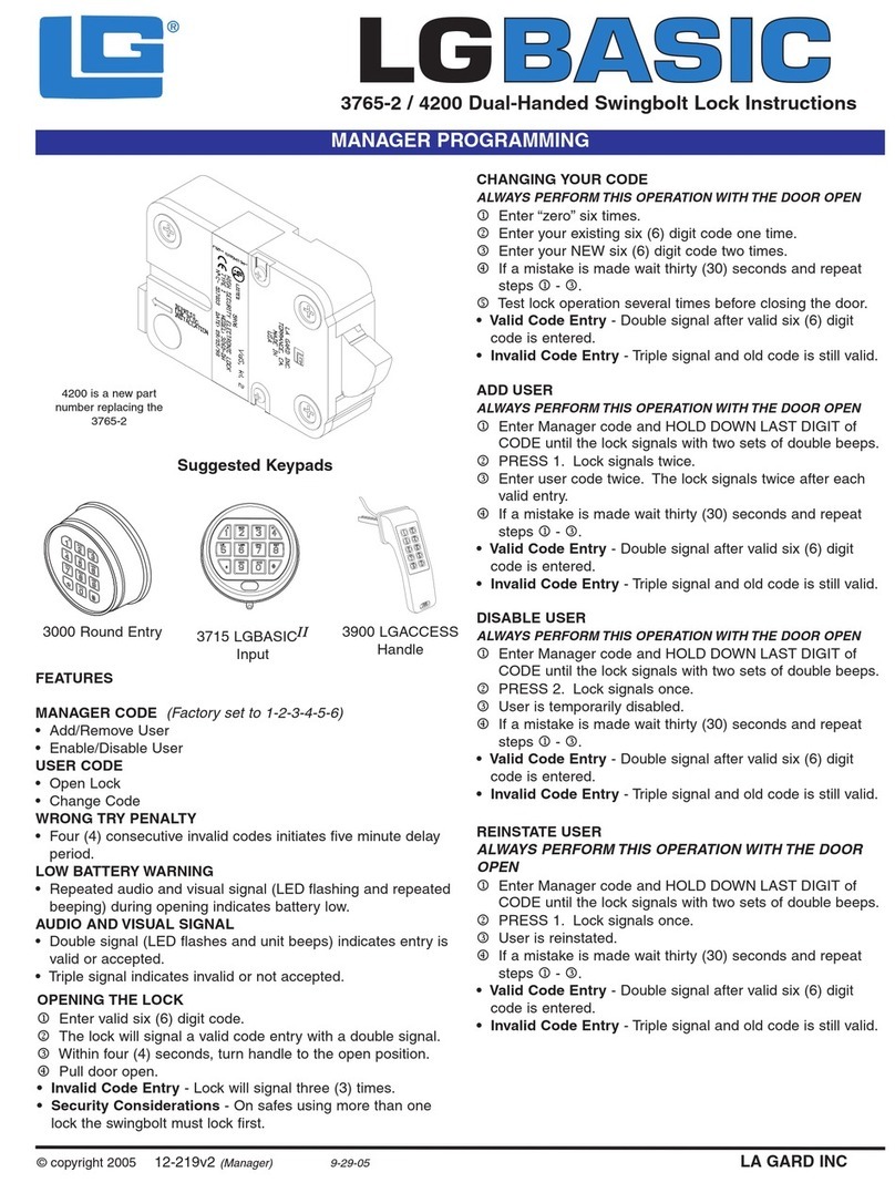
  9. LaGard 3750-K User manual

LaGard 3750-K User manual

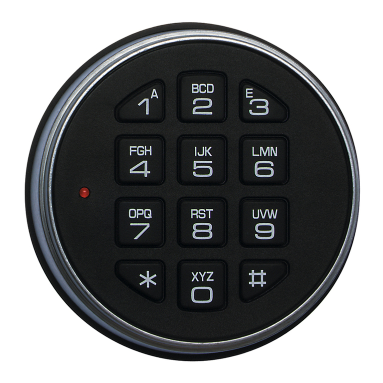
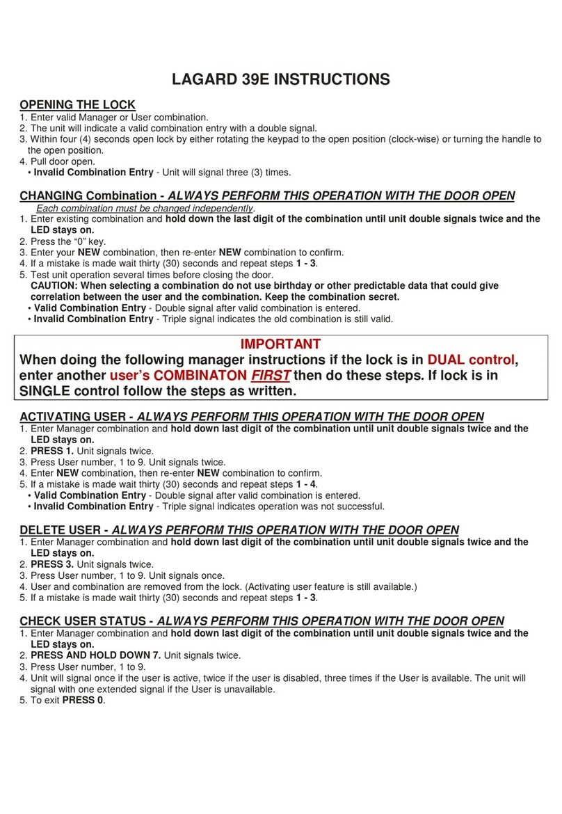
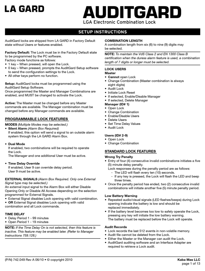
3750-K Electronic Entry Device and Dual-Handed Swingbolt Lock
INSTALLATION INSTRUCTIONS
In order to maintain the highest quality standards and ensure a problem-free application, please read this guide
thoroughly before mounting the lock.
Safeguards for Mounting
LA GARD recommends the following:
1. Complete all welds to the safe prior to installation of the electronic lock.
2. Keep metal dust, filings, etc. away from the lock.
3. Never remove the lock cover. This violates LA GARD’s warranty policy.
4. Never oil, grease, lubricate or paint the lock.
5. Keep cables away from sharp edges and moving parts.
6. Never carry the keypad or lock by the cables.
7. Use ALKALINE batteries only. (LA GARD recommends Eveready™ or Duracell™)
Figure 1
1). 3750-K Entry
[Comes with hardware pack that includes
mounting screws for entry, pin and spring and
bearing plate]
2). Dual-Handed Swingbolt Lock
[Comes with hardware pack that includes
mounting screws for lock]
1
2
Dual-Handed Swingbolt
Dimensional Drawing
The pin and spring are for use with
the Dual-Handed Swingbolt Lock
only. DO NOT use them with the
Deadbolt or Springbolt style locks.
Figure 2
©copyright 2008 (P/N) 734.018 LA GARD - A Member of the Kaba Group
Page 1 of 3
Preparation of the safe:
The holes necessary to mount the lock and entry device correspond with the standard dimensions for mechanical locks. The spindle
hole must be deburred with no sharp edges.
1). Drill mounting holes for US 8-32 or M4 screws and a cable hole, see Figure 1.
Using the two (2) 8-32 mounting screws mount the dial plate (P/N 3752) onto the tapped holes on the door.
2). The dial plate must be centered over the spindle hole. The dial plate should be mounted with the arrows in the up position.
• Tapped holes on the door should be at 12:00 and 6:00 locations, see Figure 3.
3). Install the cable protector on the entry over the cable and install over the large and small pins on the housing.
• It is important to make surethe cable will not rub on the dial plate after assembly,see Figure 4.
Mounting
Screws (2)
The 3750-K comes with two pin and spring assemblies in the hardware pak. Both should be used to ensure proper
installation of the keypad.
4). Place the spring over the small end of the pin and put one assembly in each of the holes in the back of the keypad housing,
near the battery opening, see Figure 5.
5). Feed the cable through the hole on the door.
6). Place the shoulder bushing (Figure 4)in the holes of the dial plate (Figure 6)and rotate the keypad so that the keypad is
aligned correctly.
•Aclick will be heardwhen the pin and springs snap into place in the two holes located on the dial plate, see Figure 6.
7). Keypad should be locked into place and should not move in either direction.
Shoulder
Bushing
Insert
Shoulder
Bushing
here
Figure 3 Figure 4
Figure 5 Figure 6
©copyright 2008 (P/N) 734.018 LA GARD - A Member of the Kaba Group
Page 2 of 3
DEPRESS
FOR PLUG
INSTALATION
DEPRESS
FOR PLUG
INSTALATION
14). Using the three (3) mounting screws provided by the factory, screw down the lock to the mounting plate or door.
• Make sure you do not pinch the wires, see Figure 9.
15). Secure entry cable with a wire tie, making sure that any extra cable is in a safe position and cannot be damaged by any moving
parts or sharp edges, see Figure 10.
LA GARD recommends the torque setting of 30 inch/pounds (3.4 newton/meters) when installing the Swingbolt™ lock.
8). Install the cable clamp over the cable on the inside of the door with the flat side facing the door.
9). Slide down to the hole to protect the cable from rubbing on the edge of the hole.
10). Gently pull on the cable to assure that there is no excess cable in the hole that would rub on the metal door.
11). Route the cable on the notch of the cable clamp as shown, see Figure 7.
12). Press the snap connector toward the bottom of the lock.
13). Carefully insert the entry cable plug into the lock at the “ENT” position, see Figure 8.
CHANGING YOUR BATTERY
1). Remove black plastic battery compartment cover (located at the bottom of the keypad)
by gently pulling downwardon its handle.
2). Allow the battery and its attached leads to drop down and out of the battery
compartment. If it does not drop, gently pull on the battery until it drops out.
3). The connector is easily removed by unsnapping it from the two terminals on the top of
the battery.
Never Pull on the Battery Leads
4). Connect a new 9-Volt Alkaline battery to the battery clip.
5). Gently push the battery and the leads completely up into the battery compartment.
6). Install the battery cover by placing one side of the cover in position first and then gently
pressing the other side into place.
Figure 7 Figure 8
Figure 9 Figure 10
Figure11
©copyright 2008 (P/N) 734.018 LA GARD - A Member of the Kaba Group
Page 3 of 3
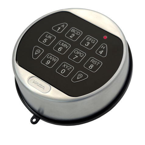
Other manuals for 3750-K

3

Other LaGard Lock manuals

LaGard LGBASIC 3710 Operation instructions

LaGard

LaGard LGBASIC 3710 Operation instructions

LaGard SMARTLINC Manual

LaGard

LaGard SMARTLINC Manual

LaGard Basic Series User manual

LaGard

LaGard Basic Series User manual

LaGard AuditGard Manual

LaGard

LaGard AuditGard Manual

LaGard LGBASIC 3765-2 User manual

LaGard

LaGard LGBASIC 3765-2 User manual

LaGard 3750-K User manual

LaGard

LaGard 3750-K User manual

LaGard 1985 User manual

LaGard

LaGard 1985 User manual

LaGard 3035 User manual

LaGard

LaGard 3035 User manual

LaGard SmartPoint User manual

LaGard

LaGard SmartPoint User manual

LaGard 39E Instruction sheet

LaGard

LaGard 39E Instruction sheet

LaGard LGBASIC 3710 Operation instructions

LaGard

LaGard LGBASIC 3710 Operation instructions

LaGard 39E User manual

LaGard

LaGard 39E User manual

LaGard ComboGard Pro 39E Manual

LaGard

LaGard ComboGard Pro 39E Manual

LaGard 3750-K User manual

LaGard

LaGard 3750-K User manual

LaGard COMBOGARD 33E User manual

LaGard

LaGard COMBOGARD 33E User manual

LaGard KEYLOCK 2270 User manual

LaGard

LaGard KEYLOCK 2270 User manual

LaGard AuditGard 66e Operation instructions

LaGard

LaGard AuditGard 66e Operation instructions

Popular Lock manuals by other brands

Assa Abloy OneSystem 519N Assembly instructions

Assa Abloy

Assa Abloy OneSystem 519N Assembly instructions

LOX EM5700D installation manual

LOX

LOX EM5700D installation manual

Easy Access EASYTOUCH 903 manual

Easy Access

Easy Access EASYTOUCH 903 manual

NCR 7360-K051 Kit instructions

NCR

NCR 7360-K051 Kit instructions

Kwikset PL1 user manual

Kwikset

Kwikset PL1 user manual

Taymor Centinel 3 installation instructions

Taymor

Taymor Centinel 3 installation instructions

Stanley QEL 200 installation instructions

Stanley

Stanley QEL 200 installation instructions

D+H LAH 65-K-BSY+ manual

D+H

D+H LAH 65-K-BSY+ manual

Simons Voss Technologies PegaSys 2.1 quick guide

Simons Voss Technologies

Simons Voss Technologies PegaSys 2.1 quick guide

Metro DataVac STARSYS WIRELESS quick start guide

Metro DataVac

Metro DataVac STARSYS WIRELESS quick start guide

SECO-LARM Enforcer E-941SA-80Q installation manual

SECO-LARM

SECO-LARM Enforcer E-941SA-80Q installation manual

COMPX OU-4260 Dimensional drawing

COMPX

COMPX OU-4260 Dimensional drawing

Schlage AD-200 installation instructions

Schlage

Schlage AD-200 installation instructions

Schlage BE365 User programming manual

Schlage

Schlage BE365 User programming manual

SUGATSUNE Lamp GS-GH5 manual

SUGATSUNE

SUGATSUNE Lamp GS-GH5 manual

SISO 14.60.290-0 user manual

SISO

SISO 14.60.290-0 user manual

Dormakaba STV 2 Series Mounting instructions

Dormakaba

Dormakaba STV 2 Series Mounting instructions

S4A U-Lock User manual and instructions

S4A

S4A U-Lock User manual and instructions

manuals.online logo
manuals.online logoBrands
  • About & Mission
  • Contact us
  • Privacy Policy
  • Terms and Conditions

Copyright 2025 Manuals.Online. All Rights Reserved.