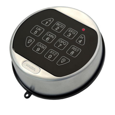
LaGard SMARTLINC Manual

SMARTLINC
Multiple Lock System
logic module & set-up instructions
AVAILABLE FEATURES
MASTER CODE (Factory set to 1-2-3-4-5-6-7-8)
• ChangeCode
• Enroll/DeleteLocks
• Install/DeleteManager
• SetLock Options
• ReprogramSoftware
• Accessto Master Menu
• DownloadAudit
• SetTime Lock Periods
MANAGER CODE (Factory set to 1-1-1-1-1-1)
• ManagesUsers
• ChangeTime Delay Values
• DownloadAudit
• ControlTemporary Time Lock
• ExtendOpen Period, if enabled
USER CODE
• Upto nine users per lock, including Manager
• OpenLock
• ChangeCode
• SetImmediate Lock
MULTIPLE LOCKS
• Upto Five
APB (Auxiliary Power Box)
• Mustbe ordered with every system no matter how many locks
areenrolled
• Providesconstant power to audit information in the event of primary
(batteryor A/C) power loss
eKEY II MODE
• Availableon each lock, if enabled
• Availablefor Manager and Users only
TIME DELAY
• Programmableon each lock
• DelayPeriod: 1 - 99 minutes
• OpenPeriod: 1 - 19 minutes
• DelayCounting mode selectable (up, down or invisible)
• TwoTime Delays Can Run At Once
TIME DELAY OVERRIDE
• Abilityto override time delay
• Assignedto User #9, if enabled
SILENT SIGNAL ALARM (Optional Alarm Box Required)
• Programmableon each lock
• Unavailableon a single lock system using AC Power
REMOTE DISABLE (Optional Alarm Box Required)
• Programmableon each lock
• Unavailableon a single lock system using AC Power
AUDIT
• Eachlock will record the last 500 operations with time, date, user
and the activity
DUAL CODE
• Programmableon each lock
• Ifset up, automatically installs User #2 (Default User
Code2-2-2-2-2-2)
• TwoCodes required to open and access Manager Menu
WRONG TRY PENALTY
• Four(4) consecutive invalid codes initiates delay period
LOW BATTERY WARNING
• Repeatedaudio and visual signal (LCD readout and repeated
beeping)during opening indicates battery low
AUDIO AND VISUAL SIGNAL
• Doublesignal (LCD readout and unit beeps) indicates entry is valid
oraccepted
• Triplesignal indicates invalid or not accepted
TIME LOCK
• TwoTime Lock periods are available for set-up
• Selectablefor each lock - Time Lock 1, Time Lock 2 or No
TimeLock
• StandardWeek (4 open periods per day)
• SpecialEvents (up to 20 close periods programmable with day and
month- i.e., January 1, July 4)
• ImmediateTime Lock (until next available open period)
• TemporaryTime Lock (to required date and time, maximum of four
(4)weeks)
• TimeLock Open Period Extension (Maximum two (2) hours),
ifenabled
• DaylightSaving Time
SYSTEM RECOMMENDATION
• Itis recommended to run the SMARTLINC software on a PC or
laptoprunning Windows® 2000 or higher.
© copyright 2005 (P/N)12-249v2 • 9/08 Kaba Mas LLC
page 1 of 8
Optional eKey II
P/N 40169
AUthorised dealer:
T: 1300 764 971
www.safeguardsafes.com.au
©copyright2005 (P/N)12-249v2•9/08 Kaba Mas LLC
page2of8
Opening SMARTLINC Set-up Software
Onceallofthesoftwarehasbeeninstalledonthecomputer,itistimetobeginsettinguptheLogicModuleandlock(s).Opentheset-
upsoftware.UsingeitherWindowsExplorerortheSTARTbutton,ndtheLAGARDfolderontheharddrive.WithintheLAGARDfolder
thereare3folderslabeledDSTUpdate,SMARTLINCandTotalAudit.OpentheSMARTLINCfolderanddoubleclickonthelenamed
SMARTLINCSETUP(seeScreen1).
SMARTLINC Set-up Software
Theopeningwindowoftheset-upsoftwareallowsthechoiceofLockSet-up,ControlUnit(LogicModule)Set-up,TimeLockSet-upand
ExitingtheSet-upsoftware(seeScreen2).
COM Port Set-up
TheCOMportmustbeselectedbeforebeginningset-up.SelecttheappropriateCOMportfromthePortMenu.ThedefaultisCOM1(see
Screens3&4).
LOCK SET-UP
Tosetupthelocks,clickontheLockSet-upbuttonontheopeningscreen(seeScreen2).Awindowwiththedefaultcongurationwill
appear(seeScreen5).Inthiswindow,selectthefeaturestobeenabledonthelocks.
• SelectthelockIDforthelocktobeprogrammed.MarkingthelockitselfwithitsIDnumberisrecommended.
• Eachlockcanbeassignedaserialnumberinthiswindow.CheckingthisboxallowstheoptionofenteringaFixedField,whichis
alphabetical,andaVariableField,whichisalphanumeric.Ifentered,thisinformationwillbeshownontheaudit.
• IfDualCodeisinstalled,User#2isautomaticallyinstalled(seescreen6).Ifinstalled,twocodeswillberequirednotonlytoopenthe
lock,buttoaccesstheManagerMenuoptionsaswell.
• UserscanonlybeconguredontheLogicModuleiftheyhavebeensetupasDeletedinthiswindow.ADeletedUserisausernumber
readyforinstallation;aBlockedUserisausernumberthatwillbeunavailableforinstallation.Installedisanautomaticfeatureavailable
onlyforUser#2whensettingtheunitupinDualCode.
• TimeDelayopenwindowanddelaytimesmaybesetupinthiswindoworfromtheLogicModule.
• If,wheninstalled,thereisalockthatwilltakelongerthan4secondstoreachandopen,theuseoftheOpenDeviceisrecommended.
TheOpenDevicewillholdthesignalgoingtothelockforone(1)minuteoruntiltheouterdoorhasbeenopenedandtheOpen
Devicedepressed.
NOTE: Open Device and Duress Alarm cannot work at the same time.
• Onceallofthefeaturesforthislockhavebeenselected,savetheset-uptoaleforlateruse.Ifalehasalreadybeensaved,itmaybe
openedfromthiswindowaswell.
Screen1
Screen2
Screen3 Screen4

©copyright2005 (P/N)12-249v2•9/08 Kaba Mas LLC
page3of8
SENDING SET-UP TO THE LOCK
This function requires the use of the Lock Programming Cable (P/N 43098) and a Serial Interface Connector.
1.ConnectpowertothelockviatheLogicModuleorsmall/largebatteryboxthroughtheportonthelockmarkedBAT.TheuseofDuracellTM
orEvereadyTMbatteriesisrecommended(seeFigure1).
2.PlugInterfaceandcableintoPCandopenSMARTLINCSet-upSoftware.
3.Plugthe43098cableintothelockthroughtheportonthelockmarkedENT.
4.SelectthelockIDforthelocktobeprogrammed.ItisagoodideatomarkthelockitselfwithitsIDnumber.
5.PresstheSendbuttononthesoftwareandthentheStartbutton(seeScreen7).
6.OnthescreenthesoftwarewillscrollthrougheachRecordNumber(1-12)asitdownloadstothelock,thenitwillshowOK.
7.Repeatsteps3-6foreachlocktobeprogrammedwiththisconguration.
NOTE: If the computer does not have a serial port, a serial to USB connector will be required.
ENT
BAT
DEPRES S
FOR PLU G
INSTALLATION
Screen5 Screen6
Figure1 Screen7

©copyright2005 (P/N)12-249v2•9/08 Kaba Mas LLC
page4of8
CONTROL UNIT (LOGIC MODULE) SET-UP
Tosetupthelogicmodule,clickontheControlUnitSet-upbuttonontheopeningscreen(seeScreen8).Awindowwiththedefault
congurationwillappear(seescreen9).InthiswindowselectthefeaturestobeenabledontheLogicModule.
• EncryptioncanbeseteitherONorOFF.ThedefaultissetforOFF.
CAUTION: If encryption is set ON, once the locks have been installed to this Logic Module, this will be the only Logic Module able to
be used with these locks.
• HemisphereissetwithadefaultforNORTH.SelecttheHemispherewheretheunitswillbeactive.
• TheDallas®key(eKEYII)optioncanbeselectedonthispage.ChecktheYESbox,thenselectwhichlockstosetupforusewitheKEYII,
(seeScreen10).
• DelayCountingDisplayissettoadefaultofCountdown.AvailableoptionsaretohaveTimeDelaycountingsequenceCountUp,
CountDownorNotDisplayed.
• TheTDMINwindowallowstheentryofaminimumTimeDelayvalue.Oncethisnumberisentered,Managershavingaccesstothetime
menuwillnotbeabletochangetheTimeDelayvaluebelowthisminimumdelayperiodnumber.ThisfeaturewillprogramALLlockson
thesystemthathaveaTimeDelayset-up.
• MultipleTimeLockperiodsareavailablebycheckingtheboxmarkedMultiTLActive(seescreen11).IfthereisnocheckintheMultiTL
Activebox,anytimelockperiodsprogrammedwillapplytoalllocksenrolledinthesystem.ForadifferentTimeLockperiodtoapplyto
aspeciclock,checktheMultiTLActivebox.ThelocksenrolledinthesystemmaybesettoTimeLockperiod1,2orNoTimeLock.
• OpenExtensionissettoNObydefault.Withthisoption,noonewillhaveaccesstotheOpenExtensionTimeMenuontheLogic
Module.SelectingYESallowstheManagerand/orUsers(asselectedinthenextoption)toaccesstheTimeLockOpenExtensionmenu
ontheLogicModule.ThosewhohaveaccesscanthenextendtheTimeLockOpenPeriodin30minuteincrements,butnomorethan
twohoursorfour(4)30minuteincrements.
• TimeMenuAccessallowsyoutoselectwhetherboththeManagerandtheUsersortheManageronlywillhaveaccesstothe
TimeMenu.
• TheLockInstallationCode(5-0-5-0-5-0)isusedtoenrollthelockstotheLogicModuleduringSystemSet-upusingtheMasterMenuon
theLogicModule.
Onceallofthefeaturesforthislockhavebeenselected,savetheset-uptoaleforlateruse.Ifalehasalreadybeensaved,itmaybe
openedfromthiswindowaswell.
Screen8
Screen10 Screen11
Screen9

©copyright2005 (P/N)12-249v2•9/08 Kaba Mas LLC
page5of8
SENDING SET-UP TO THE LOGIC MODULE
This function requires the use of the Logic Module Programming Cable (P/N 43097) and a Serial Interface Connector.
1.ConnectpowertotheLogicModule.(Requirestheuseofa9Vbattery.)DuracellTMorEvereadyTMbatteriesarerecommended.
2.PlugInterfaceandcableintoPCandopenSMARTLINCSet-upSoftware.
3.Connectthe43097cabletotheLogicModulethroughtheportonthekeypad.
4.PresstheSendbuttononthesoftware(seeScreen12).
5.ThesoftwarewillinstructyoutoactivatethePCLinkintheMasterMenuontheLogicModule(seescreen13).
NOTE: This reminder screen will display even if PC Link is already activated.
6.PressanykeytopowerupSMARTLINC.
• Displaywillshoweither“ENTERCOMBO”or“SELECTLOCK”whentwoormorelocksareinstalled.
7.Holddown“zero”untilthedisplayshows“MASTER,X-X-X-X-X-X-X-X”
8.EntertheMASTERcode.
9.Pressthe“P”buttonfour(4)timestoselectPCLink;thedisplaywillshow“PCLINK”.PresstheOKbuttontostartcommunicationwith
thePC.
10. OnthescreenthesoftwarewillscrollthrougheachRecordnumberasitdownloads,thenitwillshowOK.
• InordertoexitfromPCLink,pressthe“P”buttonthree(3)times.Whenthescreenreads“DoyouwanttoQUIT?”pressthe“OK”button
toexit.
NOTE: If the computer does not have a serial port, a serial to USB connector will be required.
DST (Daylight Savings Tine) SET-UP
This function requires the use of the Logic Module Programming Cable (P/N 43097), PC, DST Update Software and a Serial
Interface Connector.
1.Toset-upDST,clickontheDSTicononthePCdesktop.Theset-upwindowwillappear(seeScreen14).Inthiswindow,setuptheDST
datesorselectfromthepre-setlesavailable.Apre-setlehasbeencreatedfortheUSA.
2.ClickFilefromthemenubar,thenOpen.
3.SelectthelemarkedUSA.DATandclickOpen(seeScreen15).
• Thedateswillautomaticallybelledinforthenext15years(seeScreen16).
NOTE: This program will also allow the DST file to be deleted from a previously programmed Logic Module in the event the Module
must operate in a state not having DST.
Screen12
Screen14 Screen16Screen15
Screen13

©copyright2005 (P/N)12-249v2•9/08 Kaba Mas LLC
page6of8
SENDING DST (Daylight Savings Tine) SET-UP TO THE LOGIC MODULE
This function requires the use of the Logic Module Programming Cable (P/N 43097), PC, DST Update Software and a Serial
Interface Connector.
1.ConnectpowertotheLogicModule.(Requirestheuseofa9Vbattery).DuracellTMorEvereadyTMbatteriesarerecommended.
2.PlugInterfaceandcableintoPCandthenconnectthe43097cabletotheLogicModulethroughtheportonthekeypad.
3.PressanykeytopowerupSMARTLINC.
• Displaywillshoweither“ENTERCOMBO”orSELECTLOCK”whentwoormorelocksareinstalled.
4.Holddown“zero”untilthedisplayshows“MASTER,X-X-X-X-X-X-X-X”.EntertheMASTERcode.
5.Pressthe“P”buttonfour(4)timestoselectPCLink,thedisplaywillshow“PCLINK”
6.PresstheSendbuttononthesoftware.
• InordertoexitfromPCLink,pressthe“P”buttonthree(3)times.Whenthescreenreads“DoyouwanttoQUIT?”,pressthe“OK”
buttontoexit.
NOTE: If the computer does not have a serial port, a serial to USB connector will be required.
TIME LOCK SET-UP
TosetupTimeLock,clickontheTimeLockbuttonontheopeningscreen(seeScreen8).Awindowwiththedefaultcongurationwillappear
(seeScreen17).Thiswindowallowstheset-upofStandardWeekandSpecialEventsTimeLock.ItispossibletosetuptwodifferentTime
Lockperiods.
STANDARD WEEK
1.SelectTimeLock1.
• Select“Add”,“Delete”or“DeleteAll”byright-clickingthecursorintherstlineontheStandardWeekscreen(seeScreen18).
2.Select“Add”tosetuptherstTimeLockperiod.“MONfrom08:00to08:00”willautomaticallybeentered.
• ClickingintheDayboxineithertheOpenorClosedareawillproduceascrollmenuforselectingthedayoftheweekfortheTime
Lockperiod.
3.ToentertheOpenTime,highlighttheTimeboxintheOpenareaandenterthetimeusinga24-hourclock.
4.ToentertheClosetime,highlighttheTimeboxintheClosedareaandenterthetimeusinga24-hourclock.
• Oncetherstday’sTimevalueshavebeenentered,youwillbeaskedwhetherornotyouwishtocompletetherestoftheweek(see
Screens19and20).
NOTE: If the choice is made to not automatically complete the rest of the week, enter the daily Time Lock values in any day order
and press the green Step button to sort the records by day.
5.SavethisTimeLockcongurationasTimeLock1andthecompanyname.
6.SelectTimeLock2andrepeatsteps2-5.
CAUTION: Any day not completed will be considered a day in Time Lock and the units will be unavailable on that day.
Screen17 Screen18

©copyright2005 (P/N)12-249v2•9/08 Kaba Mas LLC
page7of8
TIME LOCK SET-UP EXAMPLES
• Lockavailable7daysaweekduringbusinesshours-inthiscasebusinesshoursare8amto8pm7daysaweek.(seeScreen20).
• Lockavailable6daysaweekduringbusinesshours-inthiscasebusinesshoursare8amto8pm6daysaweek,closedonSunday(see
Screen21).
• Locksetformultipletimelockperiodsinoneday.Setfor5days,closedSaturdayandSunday(seeScreen22).
SENDING TIME LOCK SET-UP TO THE LOGIC MODULE
This function requires the use of the Logic Module Programming Cable (P/N 43097) and a Serial Interface Connector.
1.ConnectpowertotheLogicModule.(Requirestheuseofa9Vbattery.)DuracellTMorEvereadyTMbatteriesarerecommended.
2.PlugInterfaceandcableintoPCandopenSMARTLINCSet-upsoftware.
3.Connectthe43097cabletotheLogicModulethroughtheportonthekeypad.
4.OpenthecorrectlefortheTimeLockperiod(1or2)thatwillbedownloadedtothislock.
5.PresstheSendbuttononthesoftware(seeScreen23).
• ThesoftwarewillinstructyoutoactivatethePCLinkintheMasterMenuontheLogicModule(seeScreens23&24).
6.PressanykeytopowerupSMARTLINC.
• Displaywillshoweither“ENTERCOMBO”orSELECTLOCK”whentwoormorelocksareinstalled.
7.Holddown“zero”untilthedisplayshows“MASTER,X-X-X-X-X-X-X-X”
8.EntertheMASTERcode.
9.Pressthe“P”buttonfour(4)timestoselectPCLink;thedisplaywillshow“PCLINK”.PressOKtostartcommunicationwiththePC.
10. OnthescreenthesoftwarewillscrollthrougheachRecordnumberasitdownloads,thenitwillshowOK.
• InordertoexitfromPCLink,pressthe“P”buttonthree(3)times.Whenthescreenreads“DoyouwanttoQUIT?”,pressthe“OK”
buttontoexit.
NOTE: If the computer does not have a serial port, a serial to USB connector will be required.
Screen19
Screen21
Screen20
Screen22

©copyright2005 (P/N)12-249v2•9/08 Kaba Mas LLC
page8of8
SPECIAL EVENTS SET-UP
TosetupSpecialEvents,clicktheTimeLockbuttonontheopeningscreen(seeScreen8).Awindowwiththedefaultcongurationwill
appear(seeScreen17).Thiswindowallowstheset-upofStandardWeekandSpecialEventsTimeLock.
SPECIAL EVENTS
• Byright-clickingwiththecursorintherstlineontheSpecialEventsscreen,select“Add”,“Delete”or“DeleteAll”(seeScreen25).
• Selecttherstboxandselect“Add”tosetuptherstSpecialEventperiod.SelectthecorrectDayandDate(1,July)fromthedrop-
downmenufortheClosedTime.ThenselectthecorrectDayandDatefromthedrop-downmenufortheOpenTime(seeScreen26).
• UptotwentySpecialEventsmaybeadded(amaximumoffourweeks)foreachyear.
NOTE: Special Events will repeat each year on that Calendar date. Floating Holidays, i.e. Thanksgiving, Labor Day, etc. cannot be
programmed.
SENDING SPECIAL SET-UP TO THE LOGIC MODULE
This function requires the use of the Logic Module Programming Cable (P/N 43097) and a Serial Interface Connector.
1.ConnectpowertotheLogicModule.(Requirestheuseofa9Vbattery.)DuracellTMorEvereadyTMbatteriesarerecommended.
2.PlugInterfaceandcableintoPCandopenSMARTLINCSet-upsoftware.
3.Connectthe43097cabletotheLogicModulethroughtheportonthekeypad.
4.PresstheSendbuttononthesoftware(seeScreen23).
5.ThesoftwarewillinstructyoutoactivatethePCLinkintheMasterMenuontheLogicModule(seeScreens23&24).
6.PressanykeytopowerupSMARTLINC.
• Displaywillshoweither“ENTERCOMBO”orSELECTLOCK”whentwoormorelocksareinstalled.
7.Holddown“zero”untilthedisplayshows“MASTER,X-X-X-X-X-X-X-X”
8.EntertheMASTERcode.
9.Pressthe“P”buttonfour(4)timestoselectPCLink;thedisplaywillshow“PCLINK”.PressOKtostartcommunicationwiththePC.
10. OnthescreenthesoftwarewillscrollthrougheachRecordnumberasitdownloads,thenitwillshowOK.
• InordertoexitfromPCLink,pressthe“P”buttonthree(3)times.Whenthescreenreads“DoyouwanttoQUIT?”,pressthe“OK”
buttontoexit.
NOTE: If the computer does not have a serial port, a serial to USB connector will be required.
TROUBLESHOOTING
Transmission Error
• Acommunicationerror(checkcableandbatteryconnectionsand/orre-startSet-upapplication)
• Thelockisnotinpre-setupmode(resetthelockwiththeresetbox)LAGARDP/N6066
No Answer
• Acommunicationerror(checkcableandbatteryconnectionsand/orre-startSet-upapplication)
• CheckCOMportsetting.TryselectingadifferentCOMportandretry.
• SMARTLINCisnotinPC-Linkmode(ActivatePCLinkinMastermenu)
Screen23 Screen24
Screen25 Screen26
Table of contents
Other LaGard Lock manuals

LaGard
LaGard 39E Instruction sheet

LaGard
LaGard 3750-K User manual

LaGard
LaGard 3750-K User manual

LaGard
LaGard AuditGard 66e Operation instructions

LaGard
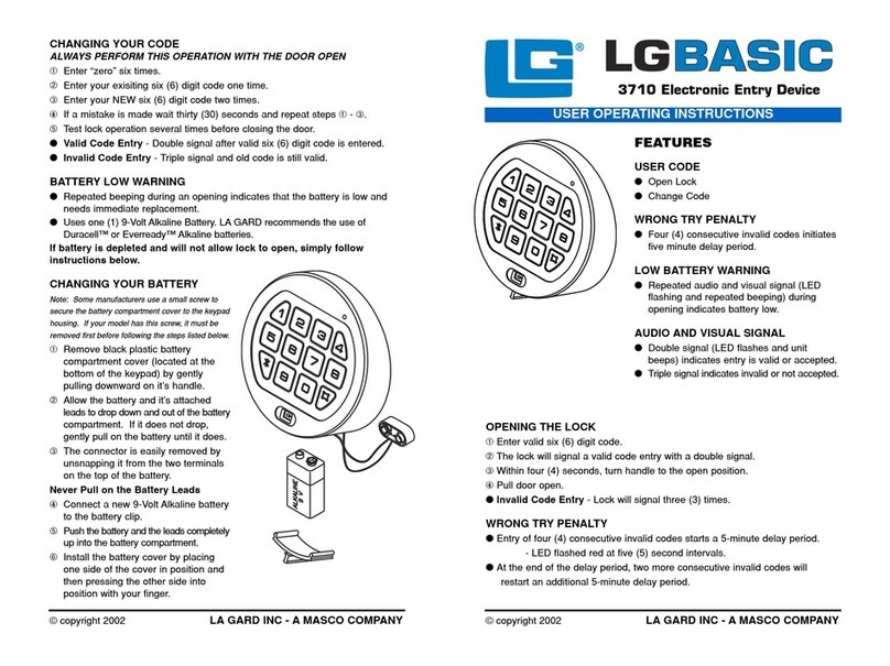
LaGard LGBASIC 3710 Operation instructions

LaGard
LaGard ComboGard Pro 39E Manual

LaGard
LaGard 39E User manual

LaGard
LaGard KEYLOCK 2270 User manual

LaGard
LaGard Basic Series User manual

LaGard
LaGard 3035 User manual