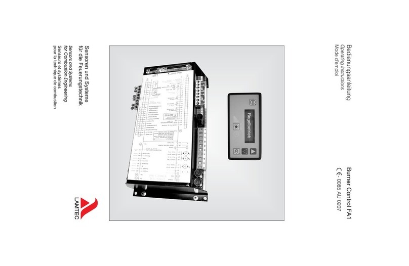
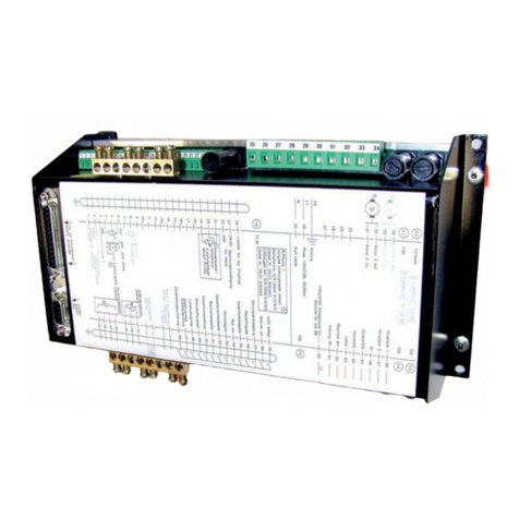
Lamtec FA1 User manual

www.lamtec.de
Sensors and Systems for Combustion Engineering
Manual
Burner Control FA1


2
Table of Contents
Table of Contents
1 General Information . . . . . . . . . . . . . . . . . . . . . . . . . . . . . . . . . . . . . . . . . . . . . . . . . . . . . . . . . 5
1.1 Validity of these Instructions. . . . . . . . . . . . . . . . . . . . . . . . . . . . . . . . . . . . . . . . . . . . . . . 5
2 Safety . . . . . . . . . . . . . . . . . . . . . . . . . . . . . . . . . . . . . . . . . . . . . . . . . . . . . . . . . . . . . . . . . . . . 6
2.1 For Your Safety . . . . . . . . . . . . . . . . . . . . . . . . . . . . . . . . . . . . . . . . . . . . . . . . . . . . . . . . 6
3 Brief Description . . . . . . . . . . . . . . . . . . . . . . . . . . . . . . . . . . . . . . . . . . . . . . . . . . . . . . . . . . . 7
4 Display and Operational Controls . . . . . . . . . . . . . . . . . . . . . . . . . . . . . . . . . . . . . . . . . . . . . 8
4.1 Use of the Operating Unit . . . . . . . . . . . . . . . . . . . . . . . . . . . . . . . . . . . . . . . . . . . . . . . . 9
4.2 Connecting the Burner Control FA1 . . . . . . . . . . . . . . . . . . . . . . . . . . . . . . . . . . . . . . . . . 9
5 Operating Description . . . . . . . . . . . . . . . . . . . . . . . . . . . . . . . . . . . . . . . . . . . . . . . . . . . . . . 10
5.1 Starting without Pilot Burner . . . . . . . . . . . . . . . . . . . . . . . . . . . . . . . . . . . . . . . . . . . . . 10
5.2 Starting with Pilot Burner . . . . . . . . . . . . . . . . . . . . . . . . . . . . . . . . . . . . . . . . . . . . . . . . 10
5.3 Starting without Control Output . . . . . . . . . . . . . . . . . . . . . . . . . . . . . . . . . . . . . . . . . . . 10
6 Commissioning . . . . . . . . . . . . . . . . . . . . . . . . . . . . . . . . . . . . . . . . . . . . . . . . . . . . . . . . . . . 11
6.1 Basic Settings . . . . . . . . . . . . . . . . . . . . . . . . . . . . . . . . . . . . . . . . . . . . . . . . . . . . . . . . 11
6.2 Password Entry . . . . . . . . . . . . . . . . . . . . . . . . . . . . . . . . . . . . . . . . . . . . . . . . . . . . . . . 11
6.3 Select Language . . . . . . . . . . . . . . . . . . . . . . . . . . . . . . . . . . . . . . . . . . . . . . . . . . . . . . 12
6.4 Start with or without Pilot Burner . . . . . . . . . . . . . . . . . . . . . . . . . . . . . . . . . . . . . . . . . . 13
6.5 Pre-purge Period . . . . . . . . . . . . . . . . . . . . . . . . . . . . . . . . . . . . . . . . . . . . . . . . . . . . . . 15
6.6 Deactivate Firing Rate Control Unit . . . . . . . . . . . . . . . . . . . . . . . . . . . . . . . . . . . . . . . . 15
6.7 Running Time of the Regular Firing Rate Input with TPS-Input . . . . . . . . . . . . . . . . . . . 16
6.8 Minimum Running Time of the Fuel/Air Ratio Control . . . . . . . . . . . . . . . . . . . . . . . . . . 16
6.9 Post-purge Time. . . . . . . . . . . . . . . . . . . . . . . . . . . . . . . . . . . . . . . . . . . . . . . . . . . . . . . 17
6.10 Delaytime of the Air Dampers During Pre-purge . . . . . . . . . . . . . . . . . . . . . . . . . . . . . . 17
6.11 Parameters of the Interface . . . . . . . . . . . . . . . . . . . . . . . . . . . . . . . . . . . . . . . . . . . . . . 18
6.12 Deactivating Valve Leakage Test . . . . . . . . . . . . . . . . . . . . . . . . . . . . . . . . . . . . . . . . . . 18
6.13 Set Pilot Burner (Maintenance Mode) . . . . . . . . . . . . . . . . . . . . . . . . . . . . . . . . . . . . . . 19
6.14 Automatic Restart after Failure . . . . . . . . . . . . . . . . . . . . . . . . . . . . . . . . . . . . . . . . . . . 20
6.15 Burner Firing Rate Controller . . . . . . . . . . . . . . . . . . . . . . . . . . . . . . . . . . . . . . . . . . . . . 21
6.15.1 Enter Set Point Values. . . . . . . . . . . . . . . . . . . . . . . . . . . . . . . . . . . . . . . . . . . . 21
6.15.2 Control Range . . . . . . . . . . . . . . . . . . . . . . . . . . . . . . . . . . . . . . . . . . . . . . . . . . 22
6.15.3 Setting the Control Thermostat . . . . . . . . . . . . . . . . . . . . . . . . . . . . . . . . . . . . . 22
6.15.4 Controller Parameters . . . . . . . . . . . . . . . . . . . . . . . . . . . . . . . . . . . . . . . . . . . . 23
6.15.5 Outside Temperature Limits. . . . . . . . . . . . . . . . . . . . . . . . . . . . . . . . . . . . . . . . 23
6.15.6 Display of the Units of the Burner Firing Rate Controller Values . . . . . . . . . . . . 23
6.15.7 Display Range in Bar . . . . . . . . . . . . . . . . . . . . . . . . . . . . . . . . . . . . . . . . . . . . . 24
6.16 Setting . . . . . . . . . . . . . . . . . . . . . . . . . . . . . . . . . . . . . . . . . . . . . . . . . . . . . . . . . . . . . . 24
6.16.1 Setting the Limit Switches of the Motors . . . . . . . . . . . . . . . . . . . . . . . . . . . . . . 24
6.16.2 Adjusting Control Elements . . . . . . . . . . . . . . . . . . . . . . . . . . . . . . . . . . . . . . . . 24
6.16.2.1 Enter the Curve . . . . . . . . . . . . . . . . . . . . . . . . . . . . . . . . . . . . . . . . . . . . . . . . 25
6.16.2.2 Clear Memory . . . . . . . . . . . . . . . . . . . . . . . . . . . . . . . . . . . . . . . . . . . . . . . . . 25
6.16.3 Programming the Ignition Point . . . . . . . . . . . . . . . . . . . . . . . . . . . . . . . . . . . . . 25
6.16.4 Programming the Base Firing Rate . . . . . . . . . . . . . . . . . . . . . . . . . . . . . . . . . . 26
6.16.5 Programming the 3rd up the 10th Point. . . . . . . . . . . . . . . . . . . . . . . . . . . . . . . 26
6.16.6 Saving Curve . . . . . . . . . . . . . . . . . . . . . . . . . . . . . . . . . . . . . . . . . . . . . . . . . . . 26
6.16.7 Changing Points . . . . . . . . . . . . . . . . . . . . . . . . . . . . . . . . . . . . . . . . . . . . . . . . 26

3
Table of Contents
6.16.8 Saving Changes . . . . . . . . . . . . . . . . . . . . . . . . . . . . . . . . . . . . . . . . . . . . . . . . 26
6.17 Fault . . . . . . . . . . . . . . . . . . . . . . . . . . . . . . . . . . . . . . . . . . . . . . . . . . . . . . . . . . . . . . . . 26
6.17.1 Reading Faults. . . . . . . . . . . . . . . . . . . . . . . . . . . . . . . . . . . . . . . . . . . . . . . . . . 26
6.17.2 Resetting Faults. . . . . . . . . . . . . . . . . . . . . . . . . . . . . . . . . . . . . . . . . . . . . . . . . 27
6.17.3 Recalling Fault History. . . . . . . . . . . . . . . . . . . . . . . . . . . . . . . . . . . . . . . . . . . . 27
7 System Operation . . . . . . . . . . . . . . . . . . . . . . . . . . . . . . . . . . . . . . . . . . . . . . . . . . . . . . . . . 28
7.1 Release Settings by Customer Interface . . . . . . . . . . . . . . . . . . . . . . . . . . . . . . . . . . . . 28
7.2 Displaying the Running Time Meter . . . . . . . . . . . . . . . . . . . . . . . . . . . . . . . . . . . . . . . . 29
7.3 Displaying Checksums and Safety Times . . . . . . . . . . . . . . . . . . . . . . . . . . . . . . . . . . . 29
7.4 Re-enter Range Limits . . . . . . . . . . . . . . . . . . . . . . . . . . . . . . . . . . . . . . . . . . . . . . . . . . 30
8 Internal Burner Firing Rate Controller . . . . . . . . . . . . . . . . . . . . . . . . . . . . . . . . . . . . . . . . . 31
8.1 Purpose . . . . . . . . . . . . . . . . . . . . . . . . . . . . . . . . . . . . . . . . . . . . . . . . . . . . . . . . . . . . . 31
8.2 Brief Description. . . . . . . . . . . . . . . . . . . . . . . . . . . . . . . . . . . . . . . . . . . . . . . . . . . . . . . 31
8.3 Range Limits . . . . . . . . . . . . . . . . . . . . . . . . . . . . . . . . . . . . . . . . . . . . . . . . . . . . . . . . . 31
8.4 Moving Screen "Actual Temperature is too high". . . . . . . . . . . . . . . . . . . . . . . . . . . . . . 31
8.5 How to Change the Burner-Firing-Rate Controller with the Customer Interface . . . . . . 31
8.6 Changing Setpoint of Burner-Firing-Rate Controller . . . . . . . . . . . . . . . . . . . . . . . . . . . 32
8.7 Input Signals . . . . . . . . . . . . . . . . . . . . . . . . . . . . . . . . . . . . . . . . . . . . . . . . . . . . . . . . . 32
8.8 Operating Description . . . . . . . . . . . . . . . . . . . . . . . . . . . . . . . . . . . . . . . . . . . . . . . . . . 32
8.9 Steam Pressure . . . . . . . . . . . . . . . . . . . . . . . . . . . . . . . . . . . . . . . . . . . . . . . . . . . . . . . 33
8.10 Control by Atmospheric Condition . . . . . . . . . . . . . . . . . . . . . . . . . . . . . . . . . . . . . . . . . 33
8.11 Setpoint Changeover . . . . . . . . . . . . . . . . . . . . . . . . . . . . . . . . . . . . . . . . . . . . . . . . . . . 33
8.12 Start-up Sequence . . . . . . . . . . . . . . . . . . . . . . . . . . . . . . . . . . . . . . . . . . . . . . . . . . . . . 34
8.13 Thermostat and Control Range . . . . . . . . . . . . . . . . . . . . . . . . . . . . . . . . . . . . . . . . . . . 35
8.14 Manual Control. . . . . . . . . . . . . . . . . . . . . . . . . . . . . . . . . . . . . . . . . . . . . . . . . . . . . . . . 37
8.15 How to Adjust the Burner Firing Rate Controller . . . . . . . . . . . . . . . . . . . . . . . . . . . . . . 37
8.16 Control Range . . . . . . . . . . . . . . . . . . . . . . . . . . . . . . . . . . . . . . . . . . . . . . . . . . . . . . . . 37
8.17 Checking the Safety Limiter . . . . . . . . . . . . . . . . . . . . . . . . . . . . . . . . . . . . . . . . . . . . . . 38
8.18 Control Mode . . . . . . . . . . . . . . . . . . . . . . . . . . . . . . . . . . . . . . . . . . . . . . . . . . . . . . . . . 38
8.19 Aides for Setting. . . . . . . . . . . . . . . . . . . . . . . . . . . . . . . . . . . . . . . . . . . . . . . . . . . . . . . 39
9 Valve Leakage Test. . . . . . . . . . . . . . . . . . . . . . . . . . . . . . . . . . . . . . . . . . . . . . . . . . . . . . . . . 40
9.1 Valve Leakage Test Flow Chart . . . . . . . . . . . . . . . . . . . . . . . . . . . . . . . . . . . . . . . . . . . 41
9.2 Calculation Example . . . . . . . . . . . . . . . . . . . . . . . . . . . . . . . . . . . . . . . . . . . . . . . . . . . 42
10 Standby . . . . . . . . . . . . . . . . . . . . . . . . . . . . . . . . . . . . . . . . . . . . . . . . . . . . . . . . . . . . . . . . . . 44
10.1 Standby mode . . . . . . . . . . . . . . . . . . . . . . . . . . . . . . . . . . . . . . . . . . . . . . . . . . . . . . . . 44
10.2 Specification of the burner sequencer function "Standby Mode" . . . . . . . . . . . . . . . . . . 45
10.3 Switching into Standby Mode via LSB module . . . . . . . . . . . . . . . . . . . . . . . . . . . . . . . 46
11 Appendix. . . . . . . . . . . . . . . . . . . . . . . . . . . . . . . . . . . . . . . . . . . . . . . . . . . . . . . . . . . . . . . . . 47
11.1 Mode Abbreviations Used . . . . . . . . . . . . . . . . . . . . . . . . . . . . . . . . . . . . . . . . . . . . . . . 47
11.2 Flame Monitoring . . . . . . . . . . . . . . . . . . . . . . . . . . . . . . . . . . . . . . . . . . . . . . . . . . . . . . 48
11.2.1 Integral Flame Monitoring (Option) . . . . . . . . . . . . . . . . . . . . . . . . . . . . . . . . . . 48
11.2.1.1 Purpose . . . . . . . . . . . . . . . . . . . . . . . . . . . . . . . . . . . . . . . . . . . . . . . . . . . . . . 48
11.2.1.2 Characteristics flame sensor . . . . . . . . . . . . . . . . . . . . . . . . . . . . . . . . . . . . . . 48
11.2.1.3 Self Monitoring . . . . . . . . . . . . . . . . . . . . . . . . . . . . . . . . . . . . . . . . . . . . . . . . . 48
11.2.2 General Information of the Optical Flame Monitoring . . . . . . . . . . . . . . . . . . . . 50
11.2.3 Optical Flame Sensors . . . . . . . . . . . . . . . . . . . . . . . . . . . . . . . . . . . . . . . . . . . 50

4
Table of Contents
11.2.3.1 Switching to Display the Flame Intensity . . . . . . . . . . . . . . . . . . . . . . . . . . . . . 50
11.3 Avoiding EMC Effects . . . . . . . . . . . . . . . . . . . . . . . . . . . . . . . . . . . . . . . . . . . . . . . . . . 51
11.4 Fault Codes . . . . . . . . . . . . . . . . . . . . . . . . . . . . . . . . . . . . . . . . . . . . . . . . . . . . . . . . . . 53
11.5 Calling Up the Condition of the Digital Inputs . . . . . . . . . . . . . . . . . . . . . . . . . . . . . . . . 71
11.6 Tips and Tricks . . . . . . . . . . . . . . . . . . . . . . . . . . . . . . . . . . . . . . . . . . . . . . . . . . . . . . . . 72
11.6.1 Set Pilot Burner . . . . . . . . . . . . . . . . . . . . . . . . . . . . . . . . . . . . . . . . . . . . . . . . . 72
11.6.2 Checking the Safety Times . . . . . . . . . . . . . . . . . . . . . . . . . . . . . . . . . . . . . . . . 72
11.7 Process Sequence Charts . . . . . . . . . . . . . . . . . . . . . . . . . . . . . . . . . . . . . . . . . . . . . . . 73
11.8 Connection Diagrams . . . . . . . . . . . . . . . . . . . . . . . . . . . . . . . . . . . . . . . . . . . . . . . . . . 81
11.9 Connection Examples of Firing Rate Input . . . . . . . . . . . . . . . . . . . . . . . . . . . . . . . . . . 83
11.10 Flame Scanner and Sensor Connection . . . . . . . . . . . . . . . . . . . . . . . . . . . . . . . . . . . . 84
11.10.1 Flame Scanner Connection. . . . . . . . . . . . . . . . . . . . . . . . . . . . . . . . . . . . . . . . 84
11.10.2 Flame Sensor Connection. . . . . . . . . . . . . . . . . . . . . . . . . . . . . . . . . . . . . . . . . 85
11.10.2.1 FFS07 Assembly . . . . . . . . . . . . . . . . . . . . . . . . . . . . . . . . . . . . . . . . . . . . . . 85
11.10.2.2 FFS08 Assembly . . . . . . . . . . . . . . . . . . . . . . . . . . . . . . . . . . . . . . . . . . . . . . 86
11.11 LAMTEC SYSTEM BUS (LSB) . . . . . . . . . . . . . . . . . . . . . . . . . . . . . . . . . . . . . . . . . . . 87
11.11.1 LSB Connection. . . . . . . . . . . . . . . . . . . . . . . . . . . . . . . . . . . . . . . . . . . . . . . . . 87
11.11.2 LSB Cable Connection . . . . . . . . . . . . . . . . . . . . . . . . . . . . . . . . . . . . . . . . . . . 89
11.12 Inernal Connecting Diagram of the Control Outputs . . . . . . . . . . . . . . . . . . . . . . . . . . . 90
11.13 Valve Leakage Test Venting Over the Roof . . . . . . . . . . . . . . . . . . . . . . . . . . . . . . . . . . 91
11.14 Switch- and Key Combinations . . . . . . . . . . . . . . . . . . . . . . . . . . . . . . . . . . . . . . . . . . . 92
11.14.1 Programming Unit . . . . . . . . . . . . . . . . . . . . . . . . . . . . . . . . . . . . . . . . . . . . . . . 92
11.14.2 Customer Interface . . . . . . . . . . . . . . . . . . . . . . . . . . . . . . . . . . . . . . . . . . . . . . 93
11.15 Feedback at Three-Point-Step Outputs . . . . . . . . . . . . . . . . . . . . . . . . . . . . . . . . . . . . . 94
11.15.1 Connect with Positive Locking. . . . . . . . . . . . . . . . . . . . . . . . . . . . . . . . . . . . . . 94
11.15.2 Fail-Safe Feedback . . . . . . . . . . . . . . . . . . . . . . . . . . . . . . . . . . . . . . . . . . . . . . 94
11.15.3 Examples of Potentiometers and Motors . . . . . . . . . . . . . . . . . . . . . . . . . . . . . 94
11.16 Replacing the Device and Components. . . . . . . . . . . . . . . . . . . . . . . . . . . . . . . . . . . . . 96
11.16.1 Replacing a Burner Control FA1 . . . . . . . . . . . . . . . . . . . . . . . . . . . . . . . . . . . . 96
11.16.2 How to Replace a Servo Motor . . . . . . . . . . . . . . . . . . . . . . . . . . . . . . . . . . . . . 96
11.16.3 How to Replace a Potentiometer. . . . . . . . . . . . . . . . . . . . . . . . . . . . . . . . . . . . 96
11.17 Changing EPROMs . . . . . . . . . . . . . . . . . . . . . . . . . . . . . . . . . . . . . . . . . . . . . . . . . . . . 97
11.18 Wiring Notes . . . . . . . . . . . . . . . . . . . . . . . . . . . . . . . . . . . . . . . . . . . . . . . . . . . . . . . . 101
11.18.1 Shields Connection . . . . . . . . . . . . . . . . . . . . . . . . . . . . . . . . . . . . . . . . . . . . . 101
11.18.2 PE Busbar . . . . . . . . . . . . . . . . . . . . . . . . . . . . . . . . . . . . . . . . . . . . . . . . . . . . 101
11.18.3 Control Cabinet Wiring . . . . . . . . . . . . . . . . . . . . . . . . . . . . . . . . . . . . . . . . . . 101
11.19 Technical Data . . . . . . . . . . . . . . . . . . . . . . . . . . . . . . . . . . . . . . . . . . . . . . . . . . . . . . . 102
11.19.1 FA1 BurnerControl. . . . . . . . . . . . . . . . . . . . . . . . . . . . . . . . . . . . . . . . . . . . . . 102
11.19.2 Customer Interface . . . . . . . . . . . . . . . . . . . . . . . . . . . . . . . . . . . . . . . . . . . . . 105
11.19.3 Programming Unit . . . . . . . . . . . . . . . . . . . . . . . . . . . . . . . . . . . . . . . . . . . . . . 107
11.20 Burner Control FA1 without integral flame detector . . . . . . . . . . . . . . . . . . . . . . . . . . . 108
11.21 Flame Scanner FFS07/FFS08 . . . . . . . . . . . . . . . . . . . . . . . . . . . . . . . . . . . . . . . . . . . 108
11.22 Declaration of Conformity . . . . . . . . . . . . . . . . . . . . . . . . . . . . . . . . . . . . . . . . . . . . . . 110

5
1 General Information
1.1 Validity of these Instructions
These instructions apply to the FA1 and in any configuration.
These devices conform to the following standards and regulations:
• DIN EN 298: 2012-11
• DIN EN 1643: 2014-09
• DIN EN 13611:2011-12
• DIN EN 60730-2-5: 2015-10
• DIN EN 60730-1:2012-10
• 2014/35/EU Low Voltage Directive
• 2014/30/EU EMC-Directive
• 2014/68/EU Pressure Equipment Directive
• (EU) 2016/426 Gas Appliance Directive
• 2011/65/EU RoHS
Test symbols: CE-0085 AU 0207
The FA1 is a control unit for combustion systems.
NOTICE
Respect the national safety regulations and standards.

6
2 Safety
2 Safety
2.1 For Your Safety
The following symbols are used in this document to draw the user's attention to important safe-
ty information. They are located at points where the information is required. It is essential that
the safety information is observed and followed, and that applies particularly to the warnings.
DANGER!
This draws the user's attention to imminent danger. If it is not avoided, it will result in death or
very serious injury. The plant including its surroundings could be damaged.
WARNING!
This draws the user's attention to the possibility of imminent danger. If it is not avoided, it may
result in death or very serious injury. The plant including its surroundings could be damaged.
CAUTION!
This draws the user's attention to the possibility of imminent danger. If it is not avoided, it may
result in minor injuries. The plant including its surroundings could be damaged.
NOTICE
This draws the user's attention to important additional information about the system or system
components and offers further tips.
The safety information described above is incorporated into the instructions.
Thus, the operator is requested to:
1 Comply with the accident prevention regulations whenever work is being carried out.
2 Do everything possible within his control to prevent personal injury and damage to prop-
erty.

7
3 Brief Description
3 Brief Description
The Burner Control FA1 is suitable for control of burners and combustion systems for gase-
ous, liquid and solid fuels, with permanent operation, also in hot air generators.
Connections for Interbus-S, PROFIBUS DP, CANopen, TCP/IP (Modbus TCP) and Modbus
RTU are available as optional equipment. The connection of other plant components e.g. O2
trim is by the LAMTEC SYSTEM BUS interface to a 9-pole Sub-D connector.
The operation is via optional PC software or programming unit. As display for end user, a cus-
tomer interface is connectable by LAMTEC SYSTEM BUS. The operation by PC software is
described in a separate manual
The FA1 continuously monitors its own functions and those of the connected control elements.
230 V outputs:
– actuation of the gas valves
– actuation of the oil valves
– actuation of the oil pump/rotary atomiser
– actuation of the ignition valve and the ignition transformer
– fan release
– fault message
– OPEN/CLOSE control signals (three-point-step or 4 ... 20 mA) for the mechanical fuel/air
ratio control
External signals to the FA1 are transmitted via floating contacts or chains of contacts.
The following signals can be pre-set:
– 3 separate safety interlock chains
– gas < max
– air pressure monitor
– pre-purge suppression
– minimum gas pressure monitor (for valve leakage test) gas >min
– flame signal
– burner on
– fuel selection
– oil pressure min / atomiser air pressure
– oil pressure max
– ignition position acknowledgement
– internal burner firing rate controller in combination with the control output

8
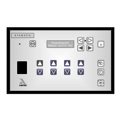
4 Display and Operational Controls
Fig. 4-1 Customer interface
Intent of the keys:
Reset
Burner firing rate/fault history up
Burner firing rate/fault history down
MANUAL mode ON/OFF
Changing display
Display: Status burner firing rate – Setpoint value/actual value of
firing rate controller (1)
4 = External firing rate – Setpoint external/internal firing rate
23 = Internal firing rate – Flame intensity (1)
– Operating hours
(1) available if activated only
Changing display
– Status
– Firing rate controller
–O
21)
– Flame intensity
Fig. 4-2 Operating Unit

9
4 Display and Operational Controls
4.1 Use of the Operating Unit
With the operating unit you may operate and the program the burner control system.
4.2 Connecting the Burner Control FA1
1. Connect the operating unit to the FA1 by using a 9-pin Cannon connector. To do so, use
the supplied connecting cable, type 663R0430.
Data transmission takes place by the LAMTEC SYSTEM BUS.
2. Alternatively:
Connect the operating unit with the cable of the customer interface. An adapter cable,
type 663R0426, is supplied for this purpose.
Disconnect the 6-pin connector from the customer interface and connect the adapter cable
to the 6-pin connector.
Fig. 4-3 Connection of the operating unit

10
5 Operating Description
(see example diagrams in chapter 11.7 Process Sequence Charts)
A signal is first fed to terminal 58 (Burner On) indicating when the burner is to start. The Burner
Control FA1 then interrogates the boiler safety interlock circuit and the air pressure monitor
contact. If it does not detect a proper condition, the text of a corresponding message is indi-
cated and the operating control stops.
If all signals are in proper condition, the fan output is activated and the channel runs to his
bottom stop as a check.
If the channel has reached his bottom stop, it opens for aeration. The valve leakage test runs
in parallel (gas operation only).
In the case of control element the aeration is used to enter and/or test the range limit. After
reaching its top position, the mechanical fuel/air ratio control element remains in the open po-
sition. The FA1 then interrogates the air pressure monitor. If this signal is in proper condtioion,
the parameter set aeration time runs. When this time has expired the channel runs to the pro-
grammed ignition position. Once the channel has reached the ignition position the ignition
transformer is activated on its own for 3 seconds. The oil pump also starts up during oil oper-
ation
Before the valves open the respective fuel safety interlock circuit must be closed.
5.1 Starting without Pilot Burner
The main valves open and together with the ignition transformer remain activated for the du-
ration of the safety time. During this time the flame signal appears.
5.2 Starting with Pilot Burner
The ignition valve and main gas 1 (in gas operation) or the ignition valve alone (in oil operation)
run open. The pilot flame forms and the flame detection detects the flame. The flame detection
sends the signal to the burner control device.
On expiry of the 1st safety time, the ignition transformer switches off. For 3 sec. (stabilisation
time) the pilot burner burns alone. Then main gas 2 or the oil valve opens and remains acti-
vated in parallel with the ignition valve for the duration of the 2nd safety time. The ignition valve
closes again at the end of this period.
3 seconds after ignition, all channels run to the programmed base firing rate point. The FA1
remains in base firing rate position until control release is given.
After control release the FA1 follows the power control unit’s default setting.
A shut off follows the cancelling of the signal of the terminal 58. The main valves close. In gas
operation, first main gas 1 and second main gas 2 closes with a delay of approx. 5 sec., in
order to allow the test line between the solenoid valves to burn out. In the event of a fault shut-
down, both close immediately.
If configured for post-purge, the air channels open again for this period.
Thereafter the FA1 is in the "OFF" mode.

11
6 Commissioning
6 Commissioning
6.1 Basic Settings
First configure the device (FA1) for the requirements of the system.
Therefore set the following parameters.
Recommendation: Use the LAMTEC PC software for Windows (available separately).
The factory standard settings are indicated by an asteriks *.
NOTICE
The parameters of release level 1 must be protected by a password against unauthorised
changes. This password must differ to ’0000’.
6.2 Password Entry
With the keys 9/8 the parameter content can be changed at 1.
With the keys 5/4 the parameter content can be changed at 100.
With the keys 3/2 the parameter content can be changed at 1000.
NOTICE
Changes does not need to be confirmed, they will be saved immediately.
Press key F3
Use keys 6 an 7 to switch to the programming interface.
Confirm with key 11 ENTER.
Confirm the warning with key F3.
Press keys 5, 7 and 8 simultaneously.
Enter the password with keys 2 ... 9 (0000 is set on delivery).
Press key 11 ENTER.
The display shows an arrow to the right and an arrow to the left above
the keys F2 and F3. This means the keys are in function.
Use keys F2 and F3 to set "PARM" in the display.
Use keys 6or 7 to select the desired parameter.

12
6 Commissioning
6.3 Select Language
Select parameter 833
Value Language Value Language Value Language
0 German* 9 Portuguese 17 Slovene
1 English 10 Polish 18 Czech
2 French 11 Turk 19 Coal-Oil-French
3 Italian 12 Croatian 20 Coal-Gas-French
4 Swedish 13 Coal-Oil-German 21 Hungarian
5 Spanish 14 Coal-Oil-English 22 Romanian
6 Dutch 15 Coal-Gas-German 26 Norse
7 Slovak 16 Coal-Gas-English 27 Russian
8 Danish

13
6 Commissioning
6.4 Start with or without Pilot Burner
Select parameter no. 774 and 775 (oil operation, gas operation).
NOTICE
2 to 4, 9, 11, 17, 19, 25, 27 The ignition flame input must monitor the ignition flame sep-
arately and P 788 must be set to 1.
9, 11 FMS only
17, 19, 25, 27 FMS with mixed fuel firing only
Nr. FMS ETA
/FA1
Short Text Description Min Max Default
774 1 1 ZüBr. ÖL Start with (1) or without (0) pilot burner for oil, (2)=oil
with continuous ignition flame
0 255 1
0 = start without pilot burner - oil operation
1 = start with pilot burner - oil operation
2 = pilot burner also active in burner operation with
continuous monitoring of the ignition flame.
Therefore P 788 has to be set to 1
3 = start with pilot burner - oil operation,
only the ignition flame may be present during ignition
(until the 2nd safety time)
4 = pilot burner also active in operation with continuous
operation monitoring of the ignition flame, only the
ignition flame may be present during ignition
(until the 2nd safety time)
(from v. 5.4/510 on)
9 = start with pilot burner - oil operation
You may start the pilot burner with terminal 70 dur-
ing operation.
11 = start with pilot burner - oil operation
only the ignition flame may be present during igni-
tion (until the 2nd safety time).
You may start the pilot burner with terminal 70 dur-
ing operation.
17 = start with pilot burner - oil operation
Before curve set change from solo operation (gas/
fuelA) to mixed mode (+oil), the pilot burner starts
to ignite oil.
19 = start with pilot burner - oil operation,
only the ignition flame may be present during igni-
tion (until the 2nd safety time).
Before curve set change from solo operation (gas/
fuelA) to mixed mode (+oil), the pilot burner starts
to ignite oil.
25 = start with pilot burner - oil operation,
You may start the pilot burner with terminal 70 dur-
ing operation.
Before curve set change from solo operation (gas/
fuelA) to mixed mode (+oil), the pilot burner starts
to ignite oil.
27 = start with pilot burner - oil operation,
only the ignition flame may be present during igni-
tion (until the 2nd safety time).
You may start the pilot burner with terminal 70 dur-
ing operation. Before curve set change from solo
operation (gas/fuelA) to mixed mode (+oil), the pilot
burner starts to ignite oil
5.1
4

14
6 Commissioning
NOTICE
2 to 4, 9, 11, 17, 19, 25, 27 The ignition flame input must monitor the ignition flame sep-
arately and P 788 must be set to 1.
9, 11 FMS only
17, 19, 25, 27 FMS with mixed fuel firing only
Nr. FMS ETA
/FA1
Short Text Description Min Max Default
775 1 1 ZüBr.Gas Start with (1) or without (0) pilot burner for gas, (2)=gas
with continuous ignition flame
0 255 1
0 = start without pilot burner - gas operation
1 = start with pilot burner - gas operation
2 = pilot burner also active in burner operation with
continuous monitoring of the ignition flame.
Therefore set P 788 to 1
3 = start with pilot burner - gas operation,
during the ignition (until the 2. safety time) only the
ignition flame may be present
4 = pilot burner also active in operation with continuous
operation monitoring of the ignition flame.
During ignition (until the 2. safety time), only the
ignition flame may be present.For this purpose P
788 has to be 1
(since v. 5.4/5o210)
9 = start with pilot burner - gas operation
You may start the pilot burner with terminal 70 dur-
ing operation.
11 = start with pilot burner - gas operation
only the ignition flame may be present during igni-
tion (until the 2nd safety time).
You may start the pilot burner with terminal 70 dur-
ing operation.
17 = start with pilot burner - gas operation
Before curve set change from solo operation (gas/
fuelA) to mixed mode (+gas), the pilot burner starts
to ignite gas.
19 = start with pilot burner - gas operation,
only the ignition flame may be present during igni-
tion (until the 2nd safety time).
Before curve set change from solo operation (oil/
fuelA) to mixed mode (+gas), the pilot burner starts
to ignite gas.
25 = start with pilot burner - gas operation,
You may start the pilot burner with terminal 70
during operation.
Before curve set change from solo operation (gas/
fuelA) to mixed mode (+gas), the pilot burner starts
to ignite gas.
27 = start with pilot burner - gas operation,
only the ignition flame may be present during igni-
tion (until the 2nd safety time).
You may start the pilot burner with terminal 70 dur-
ing operation.
Before curve set change from solo operation (oil/
fuelA) to mixed mode (+gas), the pilot burner starts
to ignite gas.
5.1
4

15
6 Commissioning
6.5 Pre-purge Period
Select parameter no. 785
If an output channel is set to flue gas re-circulation, attention must still be given to P 427.
6.6 Deactivate Firing Rate Control Unit
Select parameter no.790 (type of burner firing rate controller).
NOTICE
These parameters (P 356 - P 359, P 366, P 367, P 427, P 774, P 775 P 785, P 790, P 833)
must be adjusted to the system before commissioning. Further parameters which, although
you can alter them, only need to deviate from the standard setting in exceptional cases, are
given below.
Nr. FMS ETA
/FA1
Short Text Description Min Max Default
785 1 1 ZEIT VO Pre-purge time in seconds 0 999 30
Set the duration of pre-purge in this parameter.
The commissioning engineer sets this value.
P784 sets the lower limit of the pre-purge.
Nr. FMS ETA
/FA1
Short Text Description Min Max Default
790 1 1 Lasttyp Type of firing rate controller. 0-OFF / 1-constant control /
2-control by atmospheric conditions
0 3 0/1
Switch OFF or set the type of the internal firing rate con-
troller
0 = OFF
1 = constant control
2 = control by atmospheric condition 1
3 = control by atmospheric condition 2
This parameter defines the input from which the actual
value is should be taken. If the parameter is set to 1, the
integrated Pt100 input is used, otherwise the firing rate
input is used.
If the Pt100 input is used as the actual value signal for
the internal firing rate controller, the firing rate controller
can be deactivated with a bridge between terminals 19
and 20. In this case the firing rate is indicated by termi-
nals 3 - 6.

16
6 Commissioning
6.7 Running Time of the Regular Firing Rate Input with TPS-Input
Select parameter no. 718.
If the firing rate default is not provided by TPS signal, the parameter must be set to „0“
6.8 Minimum Running Time of the Fuel/Air Ratio Control
Select parameter no. 729
Nr. FMS ETA
/FA1
Short Text Description Min Max Default
718 1 1 Laufz L Running time in digit/min.. for TPS firing rate input (in
digit/min)
0 1200 0/500
Here, it would be preset on how fast the signal of the
external firing rate should change if the firing rate input
is provided via the TPS signal.
With the TPS signal, external firing rate would be gener-
ated through a counter which counts up or down
depending on the contact.The speed of the counter
would be set through these parameters. Preset values
are in digits per minute. Set the parameter to 0, if the fir-
ing rate input is not TPS. .
With manual mode the default firing rate is treated as
TPS firing rate via redundant feedback channel 2, in
case TPS firing rate (P 718 not equal to 0) is configured.
0 = default firing rate current or potentiometer
500 = default firing rate TPS
Nr. FMS ETA
/FA1
Short Text Description Min Max Default
729 1 2 stopVERB Minimum running time of fuel/air ratio control 10 999 10
Minimum running time of the fuel/air ratio control (in
seconds)
Set the minimum running time of the fuel/air ratio control
in seconds. This parameter slows down the ramp-up
time or ramp-down time of the burner from base firing
rate to high firing rate.

17
6 Commissioning
6.9 Post-purge Time
Select parameter 758
6.10 Delaytime of the Air Dampers During Pre-purge
NOTICE
The control output must be active.
Select parameter no. 768.
Nr. FMS ETA
/FA1
Short Text Description Min Max Default
758 1 1 ZEIT NA Post-purge time 0 1000 0
Post-purge time (in seconds)
0 = no post-purge
1000 = continuous purge (from 5.0 on)
Set the pre-purge duration after a switch OFF. The air
flaps were opened for this purpose. A fan output runs to
20 mA. The the release signal of the fan remains ON.
No post purge occurs if the parameter content is 0 and
in the case of a fault shutdown.
The actuators are not monitored in post purge mode!
The actuators only open when the flame is extin-
guished. The time begins to run immediately with clos-
ing of the magnetic valves. It may be necessary to add
this post burn time to the required post purge time
Nr. FMS ETA
/FA1
Short Text Description Min Max Default
768 1 2 KverznLE Damper delay after fan ON in seconds 0 15 5
Delay time for the flaps after switching ON the fan in
seconds (only for FAT)
Enter a delay time for opening the flaps with respect to
the ventilator release. This prevents from increasing the
power consumption of the purge motor in the star/delta
starting phase.
(from 5.4 / 52201 on)
This parameter affects even with continuous purge.

18
6 Commissioning
6.11 Parameters of the Interface
NOTICE
These parameters have to be equal to the settings of the remote control software.
Otherwise no communication is possible.
6.12 Deactivating Valve Leakage Test
Select parameter no. 772
Nr. FMS ETA
/FA1
Short Text Description Min Max Default
822 2 2 Baud S1 Baud rate of serial interface 1 0 5 4
This parameter defines the baud rate for the serial inter-
face. The standard value is parameter content 4 (19,200
baud). If the display shows problems with the serial
transmission (especially with long serial connections), it
may be helpful to drop the baud rate. This must be car-
ried out on the burner control as well as on the operat-
ing device e.g. laptop.
0 = 1200 Baud 3 = 9600 Baud
1 = 2400 Baud 4 = 19 K 2 Baud
2 = 4800 Baud 5 = 38 K 4 Baud
824 2 2 Par. S1 Parity check for serial transfer (ser.1)1 0 2 1
This parameter sets the parity bit for interface transmis-
sion. Standard is even (parameter content: EVEN=0,
NONE=1, ODD=2).
0 = even
1 = none
2 = odd
826 2 2 Adr. S1 Network address _ _ _ (ser.1)1 0 31 1
Network address of the device (serial Interface 1)
Enter the network address for the serial interface. Fac-
tory setting for the network address is 1. If more than
one device is connected via an RS422/RS485 bus, this
network address has to be changed.
Nr. FMS ETA
/FA1
Short Text Description Min Max Default
772 1 2 Dicht.Zü Valve leakge check before ignition (0-OFF / 1-ON) 0 1 1
Setting of the valve leakage test before ignition:
0 = valve leakage test before ignition is OFF
1 = valve leakage test before ignitionis ON
This parameter is only of significance if the leakage test
is activated. (Parameter 3)

19
6 Commissioning
6.13 Set Pilot Burner (Maintenance Mode)
Select parameter no. 787
Nr. FMS ETA
/FA1
Short Text Description Min Max Default
787 1 1 Wartung Maintenance mode (control unit only until stabilization
time)
020
0 = maintenance mode OFF (main valves are opened)
1 = maintenance mode active
2 = curve set switch allowed in set mode
Set the maintenance mode with this parameter. The
maintenance mode sets the pilot burner or the ignition
flame monitor. It enables to do 5 consecutive ignition
attempts without restarting with pre-purge and the leak-
age test. The burner sequencer only steps up to the
flame stabilisation time. You may not open the main
valves before the reset of this parameter.
After the 5th attempt pre-purge and leakage start auto-
matically.
Note:
A "Total Reset" resets the counter for maintenance
mode automatically i.e. the next cycle is treated as the
first and pre-purge and the leakage test are running.
Therefore, reset faults with a "Partial Reset" wherever
possible (selection switch on "Status", first channel key
2 upwards, then in addition channel key 1 downwards).
Attention: You may not use a partial reset for some
faults.
Other manuals for FA1
2
Other Lamtec Controllers manuals