Land LSP5FL User manual

Land Instruments International
Dronfield S18 1DJ
England
Telephone: (01246) 417691
Facsimile: (01246) 410585
Email: [email protected]
Internet: www.landinst.com
© Land Instruments International, 2003 Publication Nº: LSPS198.240
Issue: A 05/03
Land Instruments International
10 Friends Lane
Newtown PA 18940-1804 U.S.A.
Telephone: (215) 504 8000
Facsimile: (215) 504 0879
Email: [email protected]
Internet: www.landinst.com
User Guide
Linescanning Thermometer


Quality Assurance
User Guide
198.240
All packaging material used for this product is 100% recyclable.
This product complies with current European directives relating to electromagnetic compatibility
and safety (EMC directive 89/336/EEC; Low voltage directive 73/23/EEC).
abcdefg
ABC
The Quality Management System of Land Instruments International Ltd. is approved to BS EN ISO9001:2000
for the design and manufacture, stockholding, in-house repair and site servicing of non contact temperature
measuring instrumentation. Associated software designed and developed in accordance with TickIT.
Calibration certificates are available from our UKAS accredited Calibration Laboratory No. 0034. The Land
calibration laboratory complies with the requirements of the international standard BS EN/IEC 17025.

Safety Information
User Guide
198.240
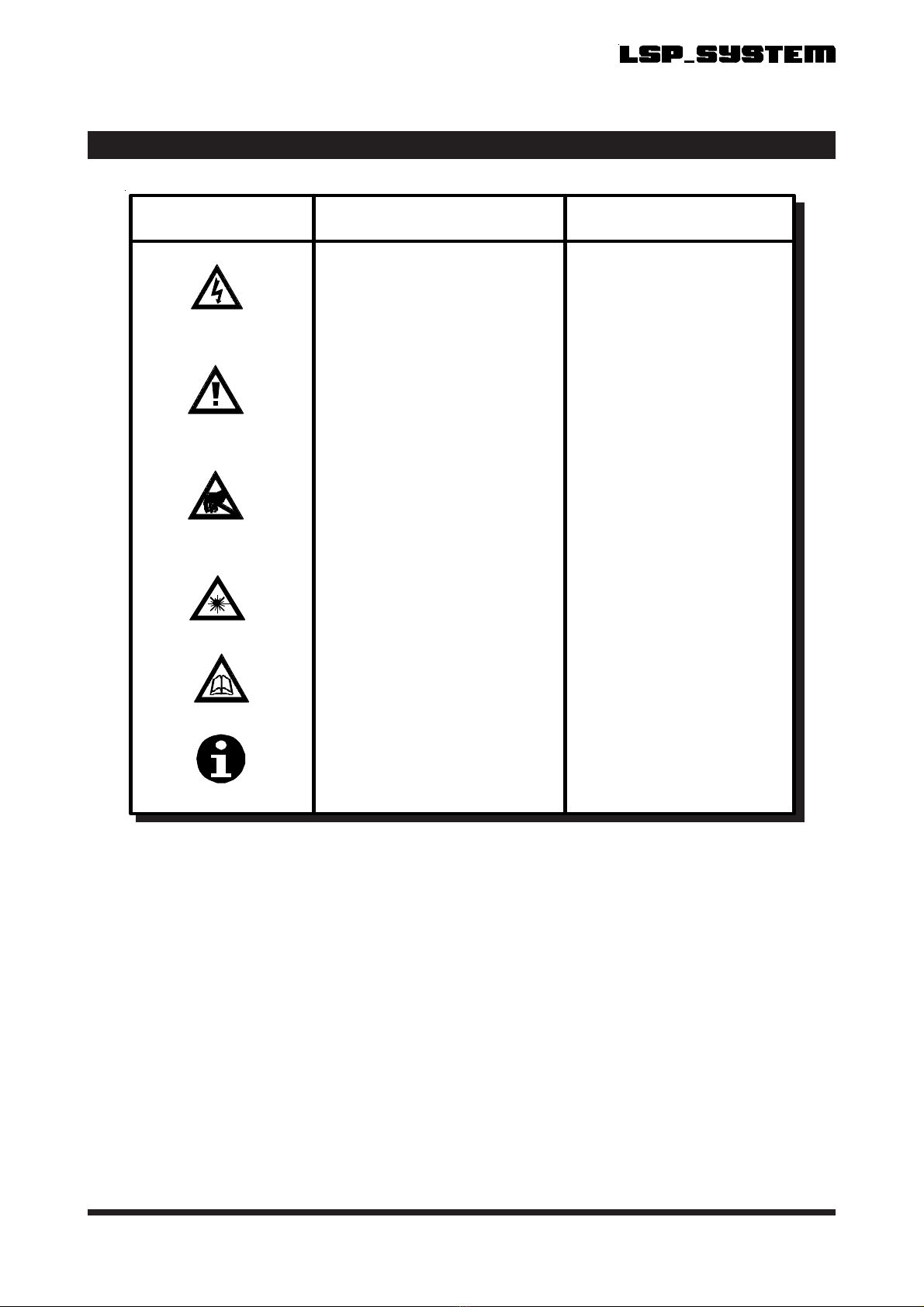
SAFETY INFORMATION
SYMBOL PUBLICATION DESCRIPTION
3
IEC 417, No.5031 Direct
Current
IEC 417, No.5032 Alternating
Current
IEC 417, No.5033 Both direct and alternating
current
IEC 617-2, No.02-02-06 Three-phase alternating
Current
IEC 417, No.5017 Earth
(ground) terminal
IEC 417, No.5019 Protective conductor terminal
IEC 417, No.5020 Fram e or chassis term inal
IEC 417, No.5021 Equipotentiality
IEC 417, No.5007 On (supply)
IEC 417, No.5008 Off (supply)
IEC 417, No.5172 Equipment protected
throughout by double
insulation or reinforced
insulation (equivalent to Class
II of IEC 536)
Safety Information
User Guide
198.240
SYMBOL PUBLICATION DESCRIPTION
ISO 3864, No. B.3.6
CautionISO 3864, No. B.3.1
WARNING
Risk of electric shock
BS EN 100015 Observe precautions for
handling electrostatic
discharge sensitive devices
Refer to the operating
instructions
BS EN 60825-1
WARNING
Laser Radiation
Note
SAFETY INFORMATION (Continued)

Blank
User Guide
198.240

Contents
User Guide
198.240
CONTENTS
QUALITY ASSURANCE
SAFETY INFORMATION
CONTENTS (This Page)
PREFACE
1.0 INTRODUCTION 1
1.1 Nomenclature
1.2 Specifications
2.0 INSTALLATION 3
2.1 Introduction
2.2 Positioning The Scanner
2.3 Alignment And Scan Direction
2.4 Installation Precautions
3.0 SERVICES 5
3.1 Electrical Connections
3.2 Water Requirements (Water Cooled Units Only)
3.3 Air Requirements (Air Purged / Cooled Units Only)
4.0 LASER ALIGNMENT 7
4.1 Using The Laser Alignment Tool
5.0 EMISSIVITY 9
5.1 Typical Emissivity Values
5.2 Setting The Emissivity Value
6.0 SCAN FREQUENCY SETTING 10
6.1 Changing The Scan frequency Setting
6.2 Scan Frequency Table
6.3 Scan Line Separation
6.4 Data Storage Requirements
6.5 Skew Angle

User Guide
Contents 198.240
CONTENTS (Continued)
7.0 INTERNAL TEMPERATURE SENSOR 13
7.1 Introduction
8.0 MAINTENANCE 14
8.1 Air Purge Services
8.2 Water And Air Cooling Services
9.0 INSTALLATION ACCESSORIES 15
9.1 Basic Mounting Plate
9.2 Right Angle Mounting Bracket
9.3 Water Cooled, Air Purge Baseplate Kit
9.4 Water Cooled End Plate Kit
9.5 Air Cooled End Plate Kit
User Guide
Preface
198.240
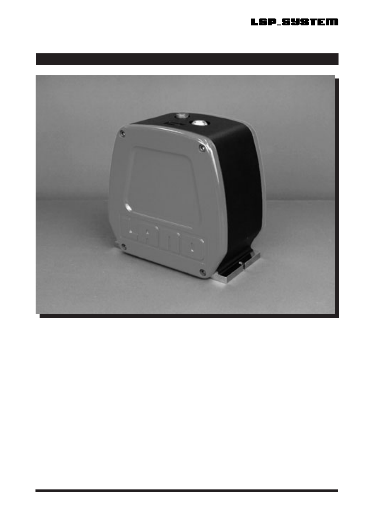
PREFACE
Fig. A - LSP Linescanning Thermometer
These instructions cover installation, operation and maintenance of the LSP Linescanning Thermometer and
should be used in conjunction with the information detailed within the LSP Linescanning Thermometer
Installation Guide, LSP Processor Installation Guide and User Guide and the LSP System Mountings and
Accessories Installation Guide.
240001

Blank
User Guide
198.240
This manual suits for next models
3
Table of contents
Other Land Thermometer manuals


