User Guide User Guide
Page 2 Page 2
Fibroptic Thermometer Fibroptic Thermometer
TheLAND UNO range of highaccuracy thermometers and rugged mountingaccessories
is designed to provide precise, non contact temperature measurement solutions.
Internal controls for emissivity or non-greyness together with selectable time functions
allow the thermometer to be configured to suit a wide range of industrial applications.
A comprehensive range of mountings is common to other LAND products maximising
commonality and simplifying sytem upgrades.
1.3 Unpacking the thermometer
The package containing the thermometer will contain the following items:
lEnvelope containing this User Guide.
lUNO Fibroptic thermometer, optic head (fitted with protection cap) and
lightguide.
lDocumentation binder with dividers.
l2.5mm Hex screwdriver.
l2.5mm flat bladed screwdriver.
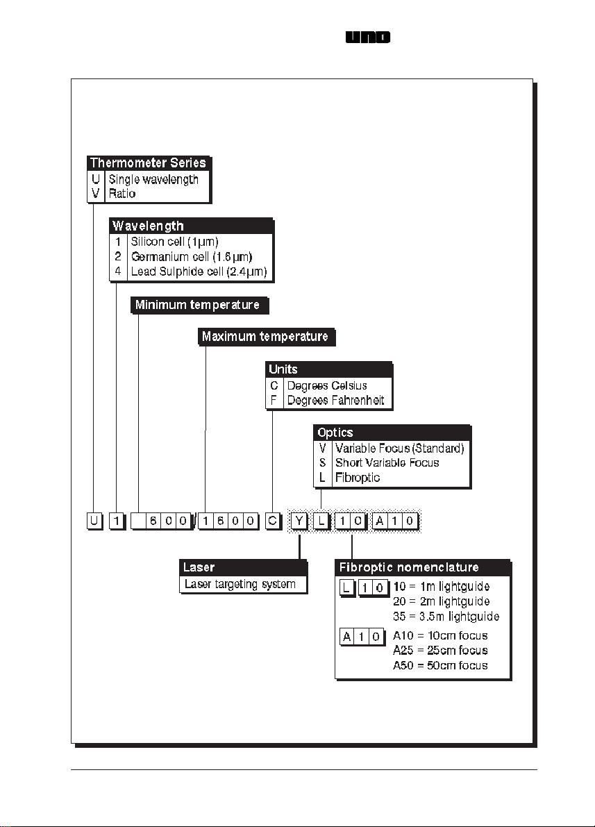
1.4 Nomenclature
The thermometer detail label is on the rear face of the thermometer above the electrical
connector. The thermometer instrument type nomenclature is explained in Fig. 2.
Make a note of your thermometer's instrument type and Serial Number in the space
provided below.
Instrument type:
Serial Number:
The optic head variant (A10, A25 or A50) is determined by the type of spacer fitted.
A10 = Red spacer (15mm long) = 10cm focus distance
A25 = Blue spacer (3mm long) = 25cm focus distance
A50 = No spacer fitted = 50cm focus distance
TheLAND UNO range of highaccuracy thermometers and rugged mountingaccessories
is designed to provide precise, non contact temperature measurement solutions.
Internal controls for emissivity or non-greyness together with selectable time functions
allow the thermometer to be configured to suit a wide range of industrial applications.
A comprehensive range of mountings is common to other LAND products maximising
commonality and simplifying sytem upgrades.
1.3 Unpacking the thermometer
The package containing the thermometer will contain the following items:
lEnvelope containing this User Guide.
lUNO Fibroptic thermometer, optic head (fitted with protection cap) and
lightguide.
lDocumentation binder with dividers.
l2.5mm Hex screwdriver.
l2.5mm flat bladed screwdriver.
1.4 Nomenclature
The thermometer detail label is on the rear face of the thermometer above the electrical
connector. The thermometer instrument type nomenclature is explained in Fig. 2.
Make a note of your thermometer's instrument type and Serial Number in the space
provided below.
Instrument type:
Serial Number:
The optic head variant (A10, A25 or A50) is determined by the type of spacer fitted.
A10 = Red spacer (15mm long) = 10cm focus distance
A25 = Blue spacer (3mm long) = 25cm focus distance
A50 = No spacer fitted = 50cm focus distance