4/93 Table of Contents
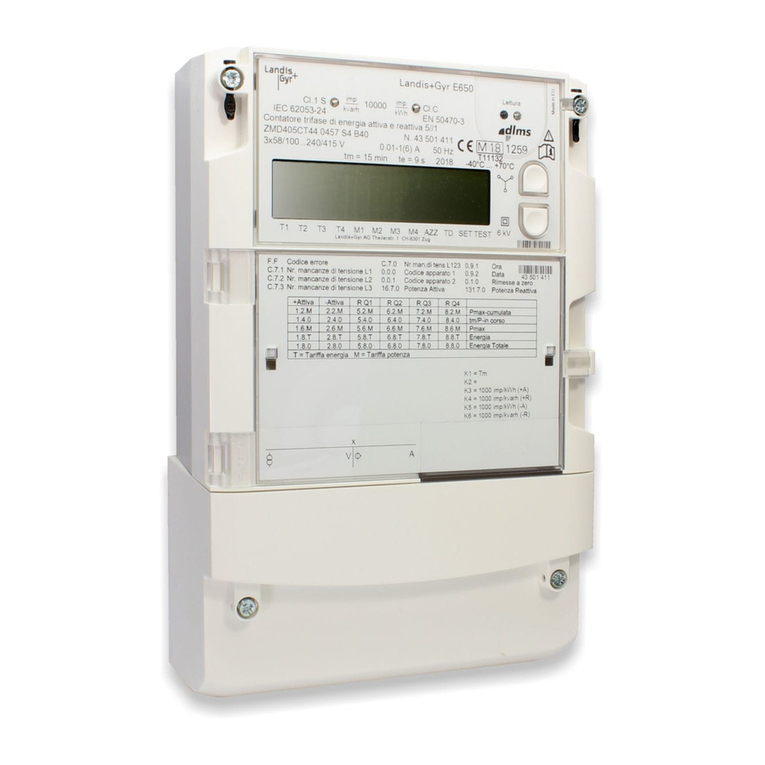
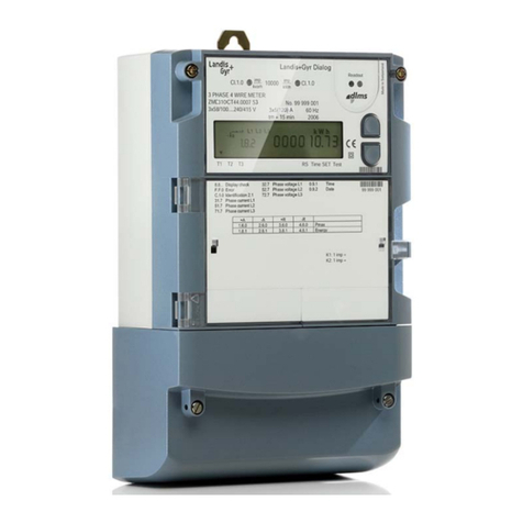
© Landis+Gyr AG D000030110 d –E650 Series 3 (ZMD400AT/CT, ZFD400AT/CT) –User Manual
Table of Contents
1Description of Unit ________________________________________________________6
1.1 Field of Application ______________________________________________________6
1.2 Characteristics _________________________________________________________6
1.3 Type Designation _______________________________________________________8
1.4 Block Schematic Diagram_________________________________________________9
1.5 Measuring System _____________________________________________________12
1.5.1 Input Signals________________________________________________________12
1.5.2 Signal Processor_____________________________________________________13
1.5.3 Measured Quantities__________________________________________________15
1.5.4 Formation of Measured Quantities _______________________________________16
1.5.5 Summation Channels _________________________________________________22
1.6 Data Profile___________________________________________________________23
1.6.1 Stored Value Profile __________________________________________________23
1.6.2 Load Profile 1 and Load Profile 2 (option)__________________________________23
1.6.3 Event Log __________________________________________________________24
1.7 Communication________________________________________________________27
1.7.1 Optical Interface _____________________________________________________27
1.7.2 Communication Units _________________________________________________27
1.8 MAP Software Tools____________________________________________________29
1.9 Anti-Tampering Features ________________________________________________30
1.9.1 DC Magnet Detection _________________________________________________30
1.9.2 Terminal Cover Detection ______________________________________________30
2Safety__________________________________________________________________31
2.1 Safety Information______________________________________________________31
2.2 Responsibilities________________________________________________________31
2.3 Safety Regulations _____________________________________________________32
2.4 Radio interference______________________________________________________32
3Mechanical Construction__________________________________________________33
3.1 Sealing ______________________________________________________________33
3.2 Face Plates___________________________________________________________36
3.3 Connections __________________________________________________________37
3.4 Connection Diagrams (Examples) _________________________________________39
3.5 Dimensions___________________________________________________________43
4Installation and De-Installation _____________________________________________44
4.1 Basic Information for Connecting Meter _____________________________________44
4.1.1 Connection to Low Voltage with Current Transformers _______________________44
4.1.2 Connection to Medium and High Voltage (Aron Circuit) _______________________45
4.1.3 Connection to Medium and High Voltage (Three-Phase Four-Wire Circuit)________46
4.2 Mounting the Meter_____________________________________________________47
4.3 Connecting Meter ______________________________________________________49
4.3.1 Connection of R-S485 Interface _________________________________________52
4.4 Check of Connections___________________________________________________53

