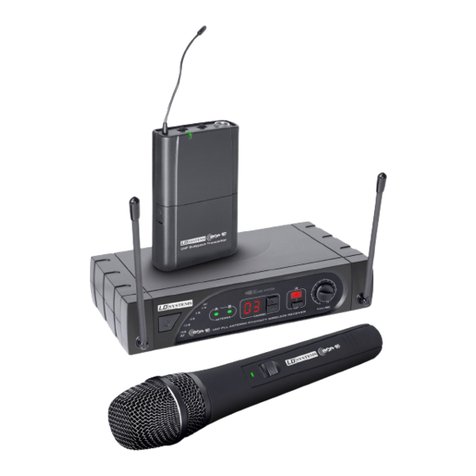
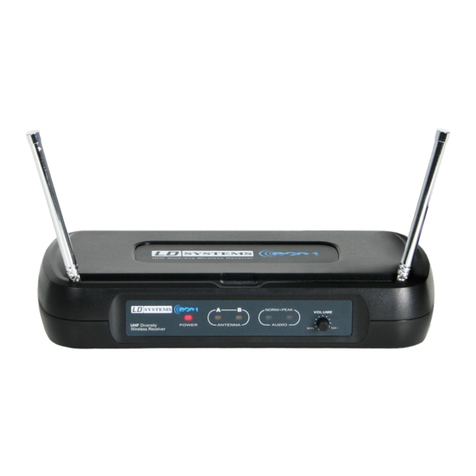
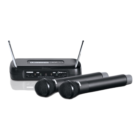
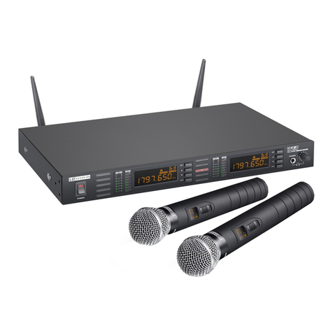
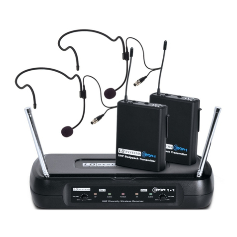
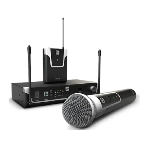
LD WSECO2 User manual

1
LD WSECO2 /LD WSECO2X2
UHF WIRELESS SYSTEMS
USER´S MANUAL
BEDIENUNGSANLEITUNG
MANUEL D`UTILISATION
MANUAL DE USUARIO
INSTRUKCJA OBSŁUGI
MANUALE D‘ USO

2
ENGLISHDEUTSCHFRANCAIS
FRANCAISFRANCAIS FRANCAISFRANCAIS ESPAÑOLPOLSKIITALIANO
You‘ve made the right choice!
We have designed this product to operate reliably over many years. LD Systems stands for this with its name and
many years of experience as a manufacturer of high-quality audio products.
Please read this User‘s Manual carefully, so that you can begin making optimum use of your LD Systems product
quickly.
You can find more information about LD SYSTEMS at our Internet site WWW.LD-SYSTEMS.COM

3
ITALIANO
POLSKI
ESPAÑOL
FRANCAIS
FRANCAIS FRANCAIS
FRANCAIS FRANCAIS
DEUTSCH
ENGLISH
LD WSECO2 / LD WSECO2X2
UHF WIRELESS SYSTEMS

4
ENGLISHDEUTSCHFRANCAIS
FRANCAISFRANCAIS FRANCAISFRANCAIS ESPAÑOLPOLSKIITALIANO
Avoid direct sunlight!
PREVENTIVE MEASURES:
1. Please read these instructions carefully.
2. Keep all information and instructions in a safe place.
3. Follow the instructions.
4. Observe all safety warnings. Never remove safety warnings or other information from the equipment.
5. Use the equipment only in the intended manner and for the intended purpose.
6. Use only sufficiently stable and compatible stands and/or mounts (for fixed installations). Make certain that wall
mounts are properly installed and secured. Make certain that the equipment is installed securely and cannot fall down.
7. During installation, observ e the applicable safety regulations for your country.
8. Never install and operate the equipment near radiators, heat registers, ovens or other sources of heat. Make certain
that the equipment is always installed so that is cooled sufficiently and cannot overheat.
9. Never place sources of ignition, e.g., burning candles, on the equipment.
10. Ventilation slits must not be blocked.
11. Do not use this equipment in the immediate vicinity of water (does not apply to special outdoor equipment -
in this case, observe the special instructions noted below. Do not expose this equipment to flammable materials,
fluids or gases.
12. Make certain that dripping or splashed water cannot enter the equipment. Do not place containers filled with
liquids, such as vases or drinking vessels, on the equipment.
13. Make certain that objects cannot fall into the device.
14. Use this equipment only with the accessories recommended and intended by the manufacturer.
15. Do not open or modify this equipment.
16. After connecting the equipment, check all cables in order to prevent damage or accidents, e.g., due to
tripping hazards.
17. During transport, make certain that the equipment cannot fall down and possibly cause property damage and
personal injuries.
18. If your equipment is no longer functioning properly, if fluids or objects have gotten inside the equipment or
if it has been damaged in anot her way, switch it off immediately and unplug it from the mains outlet (if it is a
powered device). This equipment may only be repaired by authorized, qualified personnel.
19. Clean the equipment using a dry cloth.
20. Comply with all applicable disposal laws in your country. During disposal of packaging, please separate
plastic and paper/cardboard.
21. Plastic bags must be kept out of reach of children.
FOR EQUIPMENT THAT CONNECTS TO THE POWER MAINS:
22. CAUTION: If the power cord of the device is equipped with an earthing contact, then it must be connected to
an outlet with a protective ground. Never deactivate the protective ground of a power cord.
23. If the equipment has been exposed to strong fluctuations in temperature (for example, after transport), do
not switch it on immediately. Moisture and condensation could damage the equipment. Do not switch on the
equipment until it has reached room temperature.
24. Before connecting the equipment to the power outlet, first verify that the mains voltage and frequency match
the values specified on the equipment. If the equipment has a voltage selection switch, connect the equipment to
the power outlet only if the equipment values and the mains power values match. If the included power cord or
power adapter does not fit in your wall outlet, contact your electrician.
25. Do not step on the power cord. Make certain that the power cable does not become kinked, especially at the
mains outlet and/or power adapter and the equipment connector.
26. When connecting the equipment, make certain that the power cord or power adapter is always freely
accessible. Always disconnect the equipment from the power supply if the equipment is not in use or if you want

5
ITALIANO
POLSKI
ESPAÑOL
FRANCAIS
FRANCAIS FRANCAIS
FRANCAIS FRANCAIS
DEUTSCH
ENGLISH
To prevent possible hearing damage, avoid listening at high volume levels over long periods of time.
Even exposure to short bursts of loud noise can result in hearing loss. Please keep the volume
constantly at a comfortable level.
Avoid direct sunlight!
SAFETY:
to clean the equipment. Always unplug the power cord and power adapter from the power outlet at the plug or
adapter and not by pulling on the cord. Never touch the power cord and power adapter with wet hands.
27. Whenever possible, avoid switching the equipment on and off in quick succession because otherwise this
can shorten the useful life of the equipment.
28. IMPORTANT INFORMATION: Replace fuses only with fuses of the same type and rating. If a fuse blows repea-
tedly, please contact an authorised service centre.
29. To disconnect the equipment from the power mains completely, unplug the power cord or power adapter
from the power outlet.
30. If your device is equipped with a Volex power connector, the mating Volex equipment connector must be
unlocked before it can be removed. However, this also means that the equipment can slide and fall down if
the power cable is pulled, which can lead to personal injuries and/or other damage. For this reason, always be
careful when laying cables.
31. Unplug the power cord and power adapter from the power outlet if there is a risk of a lightning strike or
before extended periods of disuse.
CAUTION
RISK OF ELECTRIC SHOCK
DO NOT OPEN
CAUTION:
Never remove the cover, because otherwise there may be a risk of electric shock. There are no user serviceable
parts inside. Have repairs carried out only by qualified service personnel.
The lightning flash with arrowhead symbol within an equilateral triangle is intended to alert the user
to the presence of uninsulated “dangerous voltage” within the product’s enclosure that may be of
sufficient magnitude to constitute a risk of electrical shock.
The exclamation mark within an equilateral triangle is intended to alert the user to the presence of
important operating and maintenance instructions.
CAUTION – HIGH VOLUME LEVELS WITH AUDIO PRODUCTS!
This equipment is intended for professional use. Therefore, commercial use of this equipment is subject to the
respectively applicable national accident prevention rules and regulations. As a manufacturer, Adam Hall is
obligated to notify you formally about the existence of potential health risks.
Hearing damage due to high volume and prolonged exposure: When in use, this product is capable of producing
high sound-pressure levels (SPL) that can lead to irreversible hearing damage in performers, employees, and
audience members. For this reason, avoid prolonged exposure to volumes in excess of 90 dB.

6
ENGLISHDEUTSCHFRANCAIS
FRANCAISFRANCAIS FRANCAISFRANCAIS ESPAÑOLPOLSKIITALIANO
SYSTEM COMPONENTS WSECO2 SYSTEMS:
All sets include the following system components:
Receiver
Batteries
Audio cable 6.3 mm mono jack to 6.3 mm mono jack
Power Supply
handheld transmitter with a
dynamic microphone capsule
Headset
Pocket transmitter
Pocket transmitterGuitar cable
Additionally, depending on the set, the following accessories are included:
LDWSECO2X2BPH - ECO2X2 Set with
pocket transmitter and headset
LDWSECO2HHD - ECO2 Set with handheld
transmitter
LDWSECO2BPG - ECO2 Set with
pocket transmitter and guitar
cable

-
+
-
+
7
ITALIANO
POLSKI
ESPAÑOL
FRANCAIS
FRANCAIS FRANCAIS
FRANCAIS FRANCAIS
DEUTSCH
ENGLISH
SYSTEM COMPONENTS WSECO2X2 SYSTEMS:
All sets include the following system components:
LDWSECO2X2BPH - ECO2X2 Set with
2 x pocket transmitters + 2 x headsets
or LDWSECO2X2HHD- ECO2X2 Set
with 2 x handheld transmitters
Dual receiver
Batteries
Power Supply
2 x handheld transmitter with a
dynamic microphone capsule
2 x headset
2 x pocket transmitter
Additionally, depending on the set, the following accessories are included:
Audio cable 6.3 mm mono jack to 6.3 mm mono jack

23
14
5
6 7
8 9
8
ENGLISHDEUTSCHFRANCAIS
FRANCAISFRANCAIS FRANCAISFRANCAIS ESPAÑOLPOLSKIITALIANO
CONNECTIONS, CONTROLS AND INDICATORS:
ECO2 RECEIVER

9
ITALIANO
POLSKI
ESPAÑOL
FRANCAIS
FRANCAIS FRANCAIS
FRANCAIS FRANCAIS
DEUTSCH
ENGLISH
CONNECTIONS, CONTROLS AND INDICATORS:
1POWER LED
Lights up once the system is properly connected to the power mains and switched on (suitable power adapter included).
2ANTENNA LEDS A / B
Indicate whether aerial input A or B is active.
3NORM LED
Lights up as soon as an audio signal is present.
4PEAK LED
Lights up if the receiver is operating at the distortion limit. To avoid distortion, reduce the signal level of the
transmitter unit.
Handheld Transmitter: Turn the GAIN knob with a suitable tool to the left.
Pocket Transmitter: 3-stage MIC / 0 dB / -10 dB switch, set to the next lowest value.
5VOLUME
Volume controller of the receiver. Turning the knob to the right increases the volume and turning it to the left
decreases it.
6AF OUTPUT
Balanced line output with XLR socket.
7LOW VOLTAGE CONNECTOR
Connection for the voltage supply of the device. Please only use the power adapter included in the product package.
8MUTE LEVEL
CAUTION: Before changing the Mute level, adjust the volume of the connected PA system to minimum.
The Mute function (noise reduction / Squelch) prevents any interference with the transmitter. In addition, sudden
noise is suppressed when the transmitted signal from the transmitter to the receiver is not strong enough.
With the transmitter switched off, adjust the Mute level with a suitable screwdriver so that noises are effectively
suppressed (when turned to the left, the noise reduction decreases, when turned to the right, it increases).
In unfavourable conditions, the transmission range may decrease when adjusting for strong noise reduction.
The Mute level controller is set to the left at the factory, therefore, the noise reduction is set at minimum strength.
This setting is suitable for the majority of applications and changes are only needed in rare cases.
9UNBAL OUTPUT
Unbalanced line output with 6.3 mm jack.
CONNECTIONS, CONTROLS AND INDICATORS:

2
23
3
1
4 4
5 5
6 6
7
8
10
ENGLISHDEUTSCHFRANCAIS
FRANCAISFRANCAIS FRANCAISFRANCAIS ESPAÑOLPOLSKIITALIANO
ECO2X2 RECEIVER
CONNECTIONS, CONTROLS AND INDICATORS:

11
ITALIANO
POLSKI
ESPAÑOL
FRANCAIS
FRANCAIS FRANCAIS
FRANCAIS FRANCAIS
DEUTSCH
ENGLISH
CONNECTIONS, CONTROLS AND INDICATORS:
1POWER LED
Lights up once the system is properly connected to the power mains and switched on (suitable power adapter included).
2RF-LED CH 1 / CH 2
Lights up when a radio signal is present on channel 1 (CH 1) or channel 2 (CH 2).
3AUDIO LED
Lights up when a radio signal is present on channel 1 (CH 1) or channel 2 (CH 2).
4VOLUME CH 1 / CH 2
Volume controller for the receiver on channel 1 (CH 1) or channel 2 (CH 2). Turning the knob to the right increases
the volume and turning it to the left decreases it.
5AF OUTPUT CHANNEL 1 / CHANNEL 2
Balanced line output with XLR connector for the receiver on channel 1 (CH 1) or channel 2 (CH 2).
6MUTE LEVEL CHANNEL 1 / CHANNEL 2
Mute controller for the receiver on channel 1 (CH 1) or channel 2 (CH 2).
CAUTION: Before changing the Mute level, adjust the volume of the connected PA system to minimum.
The Mute function (noise reduction / Squelch) prevents any interference with the transmitter. In addition, sudden
noise is suppressed when the transmitted signal from the transmitter to the receiver is not strong enough.
With the transmitter switched off, adjust the Mute level with a suitable screwdriver so that noises are effectively
suppressed (when turned to the left, the noise reduction decreases, when turned to the right, it increases).
In unfavourable conditions, the transmission range may decrease when adjusting for strong noise reduction.
The Mute level controller is set to the left at the factory, therefore, the noise reduction is set at minimum strength.
This setting is suitable for the majority of applications and changes are only needed in rare cases.
7LOW VOLTAGE CONNECTOR
Connection for the voltage supply of the device. Please only use the power adapter included in the product package.
82 IN 1 MIX UNBAL OUTPUT
Unbalanced line output with 6.3 mm jack. The audio signal consists of a mix of signals from the channels 1 and 2
(CHANNEL 1 + CHANNEL 2). The volume ratio of the two channels can be adjusted using the volume knob (no. 4) of
channels 1 and 2.
CONNECTIONS, CONTROLS AND INDICATORS:

B
A
6
7
UHFBodypackTransmitter
5
1
4 3 2
8
12
ENGLISHDEUTSCHFRANCAIS
FRANCAISFRANCAIS FRANCAISFRANCAIS ESPAÑOLPOLSKIITALIANO
POCKET TRANSMITTER:
1TRANSMITTER ANTENNA
To ensure optimal radio transmission, do not touch,
bend or cover the antenna.
2INPUT
3 pin mini XLR input for headset, lavalier and instrument
microphones, as well as guitar cable. A list of all models
is located in the specifications.
3MIC / 0 DB / -10 DB
Adjust the input sensitivity.
LDWSECO2: Adjust the sensitivity so that when a
signal is present (voice, vocals, guitar...), the green
signal LED (NORM) on the receiver lights up. As soon
as the red PEAK LED lights up, reduce the sensitivity
by turning the 3 stage MIC / 0 dB / -10 dB switch to
the next lowest value, otherwise unwanted distortion
may occur.
LDWSECO2X2: Adjust the sensitivity so that when a
signal is present (voice, vocals, guitar...), the green
signal LED (NORM) on the receiver lights up. As soon
as the audio signal begins to distort, reduce the
sensitivity by turning the 3 stage MIC / 0 dB / -10 dB
switch to the next lowest value.
4ON / STANDBY / OFF
When the transmitter is turned on (switch is in
STANDBY / ON position), the red LED flashes briefly to
indicate the battery status and goes out immediately
if batteries with sufficient charge are inserted. In
STANDBY position, the transmitter is in operation, but
the audio signal is muted.
5BATTERY STATUS LED
As soon as the red LED lights up to indicate the
battery status, replace the batteries immediately.
6ATTACHING THE PACK TRANSMITTER
Attach the transmitter to a belt (Figure A) or guitar
strap (Figure B) as shown here.

13
ITALIANO
POLSKI
ESPAÑOL
FRANCAIS
FRANCAIS FRANCAIS
FRANCAIS FRANCAIS
DEUTSCH
ENGLISH
POCKET TRANSMITTER:
7BATTERY REPLACEMENT
As soon as the red LED lights up to indicate the
battery status, please replace the batteries by pres-
sing down on the battery compartment cover at the
marked position (OPEN) and slide it to the side.
Insert two 1.5 V AA size alkaline batteries (LR6, AA)
as in the illustration on the transmitter back and
close the battery compartment cover by pressing the
marked position (CLOSE) of the cover and then slide
it to the side.
If the transmitter is not in use for a long period of time,
remove the batteries from the battery compartment.
8CHARGE
Low voltage socket for 3.5 mm barrel connector for
charging size AA batteries ( + inside, - outside).
- Use only a charger suitable for the batteries used and
be aware of the maximum permissible charging time.
- Please note that batteries inserted in the battery
compartment are switched in series!
- Never try to charge non-rechargeable batteries
Failure to comply with above instructions may result
in a fire or explosion hazard!

1
4
5
6
2
3
7
14
ENGLISHDEUTSCHFRANCAIS
FRANCAISFRANCAIS FRANCAISFRANCAIS ESPAÑOLPOLSKIITALIANO
1MICROPHONE HEAD
With dynamic microphone capsule.
2GAIN
Setting the microphone volume. Turning the knob to the right
increases the volume and turning it to the left decreases it.
LDWSECO2: Adjust the sensitivity so that when a signal is pre-
sent (voice, vocals, guitar...), the green signal LED (NORM) on the
receiver lights up. As soon as the red PEAK LED lights up, reduce
the level accordingly, otherwise undesirable distortion may occur.
LDWSECO2X2: Adjust the sensitivity so that when a signal is
present (voice, vocals, guitar...), the green signal LED (NORM)
on the receiver lights up. Once the audio signal begins to
distort, reduce the level accordingly.
3RF POWER H / L
For a majority of applications, set the switch to H (= high
power). To increase battery life, switch to L (= low power)
for applications with a small distance between transmitter
and receiver. Before the event, please check whether the low
transmission power is sufficient.
4BATTERY COMPARTMENT
Insert two 1.5 V AA size alkaline batteries (LR6 Mignon) as in the
illustration inside the battery compartment. If the transmitter is
not in use for a long period of time, remove the batteries from
the battery compartment.
5BATT LED
As soon as the red LED lights up to indicate battery status,
replace the batteries immediately.
6ON/OFF SWITCH
When the transmitter is turned on, the red LED flashes briefly
to indicate the battery status and goes out immediately if
batteries with sufficient charge are inserted.
7BATTERY REPLACEMENT
As soon as the red LED lights up for battery status display,
please replace the batteries by unscrewing the battery cover
counter-clockwise from the transmitter and after changing the
batteries screw it back on in the opposite direction.
HANDHELD TRANSMITTER:

15
ITALIANO
POLSKI
ESPAÑOL
FRANCAIS
FRANCAIS FRANCAIS
FRANCAIS FRANCAIS
DEUTSCH
ENGLISH
OPTIMISATION OF THE RADIO TRANSMISSION:
• Aim the transmitter directly at the receiver ("line-of-sight" contact between the devices).
• Do not position the receiver near metal objects/surfaces or digital devices (CD players,
computers, etc.).
• Position the receiver so that it is not directly in front of a wall and is at least 1 m above
the floor.
• Mobile phones, two-way radios and the like, may affect the radio link between the transmitter and
recipient and should not be used near the transmitter.

16
ENGLISHDEUTSCHFRANCAIS
FRANCAISFRANCAIS FRANCAISFRANCAIS ESPAÑOLPOLSKIITALIANO
TROUBLESHOOTING:
PROBLEM DISPLAY SOLUTION
No audio signal or
low level
Receiver ECO2: Neither antenna A nor
antenna B LED is lit.
Receiver ECO2X2: RF LED does not light up.
Verify that the transmitter is turned on.
Check the batteries in the transmitter.
Receiver: Power LED is not lit Verify the power supply.
Receiver ECO2: Neither antenna A nor
antenna B LED is lit.
Receiver ECO2X2: RF LED does not light up.
Transmitter: Device is turned on. Charge
status of the batteries is ok.
Verify that transmitter and receiver have
the same radio frequency.
Bring the GAIN switch on the transmitter to
position H (= high power).
Reduce the distance between transmitter
and receiver.
Make sure that there is a direct line of
sight between the transmitter and receiver.
Make sure that the antennas of the receiver
are aligned upward and into a V-shape.
Reduce the amount of noise reduction
(MUTE LEVEL)
Receiver ECO2: Antenna A or Antenna B
LED is lit.
Receiver ECO2X2: RF LED lights up.
Pocket Transmitter: The ON / STANDBY /
OFF switch is in the STANDBY position.
Turn the ON / STANDBY / OFF switch on the
transmitter to the ON position.
Receiver ECO2: Antenna A or Antenna B
LED is lit.
Receiver ECO2X2: RF LED lights up.
Receiver ECO2: Signal LED NORM is not lit
when an audio signal is present.
Receiver ECO2X2: Signal LED AUDIO
is not lit when an audio signal is present.
Increase the signal level or the sensitivity
of the transmitter.
Distortion and inter-
ference
Receiver: Radio signal indicator lights up Remove possible sources of interference
(digital devices, other wireless systems).
Increase the level of noise reduction (MUTE
level) on the receiver.
Distorted sound Transmitter: The red LED to indicate battery
status lights up.
Receiver ECO2: The red PEAK LED indicator
of the receiver lights up.
Replace the batteries in the transmitter.
Reduce the signal level or the sensitivity of
the transmitter.

17
ITALIANO
POLSKI
ESPAÑOL
FRANCAIS
FRANCAIS FRANCAIS
FRANCAIS FRANCAIS
DEUTSCH
ENGLISH
RECEIVER
Model name: LDWSECO2R LDWSECO2X2
Receiver type: diversity non diversity
Modulation: FM
Frequency range: 863.100 MHz - WSECO2R1
863.900 MHz - WSECO2R2
864.500 MHz - WSECO2R3
864.900 MHz - WSECO2R4
863.100 / 864.500 MHz -
WSECO2X2R1
863.900 / 864.900 MHz -
WSECO2X2R2
Channels: 1 2
Antenna connectors: Fixed Antenna
Frequency response: 60 - 16.000 Hz
Squelch: Mute Level
Signal-to-noise ratio: >105 dB
Balanced output: XLR 2 x XLR
Unbalanced output: 6.3 mm jack -
Unbalanced mix output: -6.3 mm jack
Audio output level (balanced): -12 dBV
Audio output level (unbalanced): -18 dBV
Controls: volume 2 x volume
Indicators: power, HF-indicator antenna A/B,
audio signal, peak
power, RF-indicator channel 1 / 2,
audio signal channel 1 / 2
Operating voltage: 12 - 18 V DC, 300 mA 12 - 18 V DC, 300 mA
Operating temperature range: -10°C … 45°C
Relative humidity in operation: 25% … 85%
Dimensions (W x H x D): 235 x 44 x 118 mm
Weight: 0,4 kg 0,4 kg
Accessories included: power adapter, audio cable power adapter, audio cable
SPECIFICATIONS:

18
ENGLISHDEUTSCHFRANCAIS
FRANCAISFRANCAIS FRANCAISFRANCAIS ESPAÑOLPOLSKIITALIANO
HANDHELD TRANSMITTER
Model name: LDWSECO2MD
Modulation: FM
Frequency range: 863.100 MHz - WSECO2MD1
863.900 MHz - WSECO2MD2
864.500 MHz - WSECO2MD3
864.900 MHz - WSECO2MD4
Channels: 1
Microphone type: dynamic
Polar pattern: cardioid
Frequency response: 60 - 16.000 Hz
RF output power: 10 mW
Controls: Power on/off, gain, HF power H / L
Indicators: battery low
Power supply: 2 x AA battery
Operating time: up to 10 h (depending on batteries)
Operating temperature range: -10°C … 45°C
Relative humidity range in operation: 25% … 85%
Dimensions (L x Ø): 250 x 53 mm
Weight: 0,28 kg
Accessories included: 2 x AA battery
SPECIFICATIONS:

19
ITALIANO
POLSKI
ESPAÑOL
FRANCAIS
FRANCAIS FRANCAIS
FRANCAIS FRANCAIS
DEUTSCH
ENGLISH
SPECIFICATIONS:
BODYPACK TRANSMITTER
Model name: LDWSECO2BP
Modulation: FM
Frequency range: 863.100 MHz - WSECO2BP1
863.900 MHz - WSECO2BP2
864.500 MHz - WSECO2BP3
864.900 MHz - WSECO2BP4
Channels: 1
Input: 3-pin mini-XLR
Frequency response: 60 - 16.000 Hz
RF output power: 10 mW
Controls: On / Standby / Off, triple gain switch
Indicators: battery low
Power supply: 2 x AA batteries
Operating time: up to 10 h (depending on batteries)
Operating temperature range: -10°C … 45°C
Relative humidity range in operation: 25% … 85%
Dimensions (W x H x D): 65 x 85 x 23 mm
Weight (without batteries): 0,1 kg
Accessories included: 2 x AA battery
SPECIFICATIONS:

20
ENGLISHDEUTSCHFRANCAIS
FRANCAISFRANCAIS FRANCAISFRANCAIS ESPAÑOLPOLSKIITALIANO
MICROPHONE
Model name: LDWS100MH1 LDWS100MH3
Microphone type: headset headset
Capsule: back-electret condenser back-electret condenser
Polar pattern: cardioid cardioid
Frequency response: 20 - 20.000 Hz 70 - 16.000 Hz
Connector: 3-pin mini-XLR 3-pin mini-XLR
Accessories included: foam windscreen foam windscreen
Features: - -
Model name: LDHSAE1 LDWS100ML
Microphone type: headset lavalier microphone
Capsule: back-electret condenser back-electret condenser
Polar pattern: bi-directional cardioid
Frequency response: 80 - 16.000 Hz 20 - 20.000 Hz
Connector: 3-pin mini-XLR 3-pin mini-XLR
Accessories included: foam windscreen foam windscreen
Features: water-repellent -
Model name: LDWS1000MW LDHSM1
Microphone type: wind instrument microphone headset
Capsule: back-electret condenser back-electret condenser
Polar pattern: cardioid noise cancelling
Frequency response: 50 - 18.000 Hz 70 - 16.000 Hz
Connector: 3-pin mini-XLR 3-pin mini-XLR
Accessories included: foam windscreen foam windscreen
Features: -water-repellent
GUITAR CABLE
Model name: LDWS100GC
Connector 1: 3-pin mini-XLR
Connector 2: 6.3 mm jack
Lenght: 1.5 m
SPECIFICATIONS:
Other manuals for WSECO2
1
This manual suits for next models
1
Table of contents
Languages:
Other LD Microphone System manuals