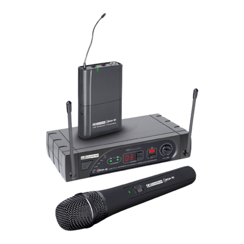
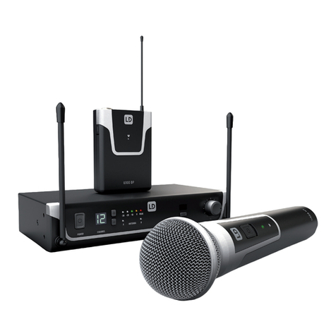
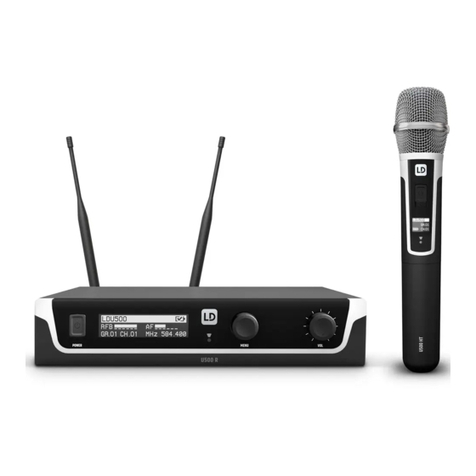
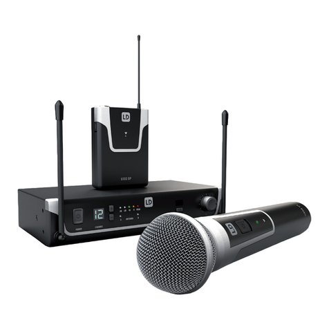
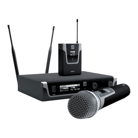
LD WS1G8 User manual

USER´S MANUAL
BEDIENUNGSANLEITUNG
MANUEL D`UTILISATION
MANUAL DE USUARIO
INSTRUKCJA OBSŁUGI
MANUALE D‘ USO
LD WS1G8
192 CHANNEL UHF TRUE DIVERSITY WIRELESS SYSTEM

2
ENGLISHDEUTSCHFRANCAIS
FRANCAISFRANCAIS FRANCAISFRANCAIS ESpAñoLpoLSKIITALIANo
Thank you for choosing LD Systems!
We have designed this product to operate reliably over many years. Therefore LD Systems guarantees for high
quality products with its name and many years of experience as a producer.
Please take a few moments to read these instructions carefully, as we want you to enjoy your new LD Systems
products quickly and to the fullest.
For information about LD Systems check out our website WWW.LD-SYSTEMS.COM
Introduction
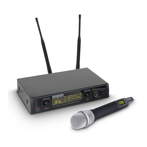
The LD Systems WS1G8 is an advanced 192 channel true diversity UHF wireless system delivering natural
sound with a wide dynamic range, high S/N ratio and low THD in the frequency range from 1785 - 1800 MHz. It
provides consistent audio transmission from 50 Hz to 16 kHz. Handheld and bodypack feature convenient LCD
indication of channel, group and battery status. Automatic channel scanning, infrared frequency sync and the
backlit multifunction receiver display facilitate system setup and operation. The operating time ranges up to 13
hours with high quality AA size batteries.

3
ITALIANOPOLSKIESPAÑOL
FRANCAISFRANCAIS FRANCAISFRANCAIS FRANCAISDEUTSCHENGLISH
LD WS1G8
192 CHANNEL UHF TRUE DIVERSITY WIRELESS SYSTEM

4
ENGLISHDEUTSCHFRANCAIS
FRANCAISFRANCAIS FRANCAISFRANCAIS ESpAñoLpoLSKIITALIANo
1. Please read this information carefully.
2. Keep all information and instructions in a safe place.
3. Please follow the instructions.
4. Please observe all warnings. Don‘t remove safety instructions or any other information located on the device.
5. Use the device only in the intended manner.
6. Use only stable and appropriate stands and/or mounts when the device is permanently installed. Make certain
that wall brackets are firmly secured. Make certain that the unit is installed securely and cannot fall down.
7. When installing please observe the corresponding safety standards for your country.
8. Do not install the device near radiators, heat accumulators, ovens or other sources of heat. Make certain that
the device is always installed so that is cooled sufficiently and cannot overheat.
9. Do not place open sources of ignition, e.g., burning candles, on the device.
10. Do not cover ventilation slots.
11. Do not operate the device in the immediate vicinity of water. Do not expose this equipment to combustible
materials, liquids or gases.
12. Please make certain that dripping or splashing water cannot get inside the device. Do not put objects filled
with fluids, such as vases or drinking vessels, on top of the device.
13. Make certain that objects cannot fall into the device.
14. Use the device only with accessories with which the manufacturer intends the device to be used.
15. CAUTION: If this device has a mains connector equipped with protective earth, it must be connected to a
mains socket with a protective ground connection. Never disable the function of the protective ground connection
of the included power cord.
16. Do not turn on the device immediately if it was exposed to strong temperature fluctuations (for example after
transportation). Moisture and condensation may damage the device. Leave the device switched off until it has
reached room temperature.
17. Do not open the device and do not make any changes to the device.
18. Before connecting to mains power, make certain that the mains voltage and the mains frequency are the
same as the operating values of the device (see type label). If the device is equipped with a supply voltage selec-
tor switch, make certain that the values of the device match the values of the mains power before connecting.
If the plug on the included cord does not fit your mains outlet, contact your electrician.
19. Make certain that the power cord is not stepped on. Protect the power cord against pinching, especially at
the device plug and the power plug.
20. In order to prevent damage or accidents, for example, due to tripping hazards, check all connections once
you have connected the device.
21. When connecting the device, make certain that the power plug remains readily accessible.
Always pull out the power plug when the device is not in use or when you clean the device. Disconnect the
power cord by pulling the plug not the cable. Never touch the power cable and power adapter with wet hands.
22. Avoid switching the device on and off at short intervals, because it may shorten the durability of the device.
23. IMPORTANT: Replace fuse only by fuse of same type and rating! If fuse blows repeatedly please contact
authorized service center!
24. In order to disconnect the device completely from the mains voltage, the power plug must be unplugged.
25. If your device is equipped with a Volex power connector, the matching Volex device plug must be unlocked
in order to disconnect it. This also means that a tug on the power cord can pull the device out of place, thus
causing personal injuries and/or property damage. Thus please make certain to route your cables carefully.
PREVENTIVE MEASURES:

5
ITALIANOPOLSKIESPAÑOL
FRANCAISFRANCAIS FRANCAISFRANCAIS FRANCAISDEUTSCHENGLISH
ENGLISH
26. If there is a risk of lightning strike or during extended periods of disuse, unplug the power plug.
27. During transport, make certain that the equipment being transported cannot fall down and possibly
cause personal injuries and/or property damage.
28. If your device no longer works properly, if it has been exposed to liquids or an object has fallen inside it or
if it has been damaged in some other manner, turn the device off immediately und unplug the power plug. This
device should be repaired only by authorized experts.
29. Use only a dry cloth to clean the device.
30. Comply with all of the disposal laws that are applicable in your country. During disposal, please separate
plastic and paper/cardboard.
31. Plastic bags must be kept out of the reach of children.
CAUTION
RISK OF ELECTRIC SHOCK
DO NOT OPEN
PREVENTIVE MEASURES:
CAUTION:
To reduce the risk of electric shock, do not remove cover (or back). No user serviceable parts inside. Refer
servicing to qualified personnel.
The lightning flash with arrowhead symbol within an equilateral triangle is intended to alert the
user to the presence of uninsulated “dangerous voltage” within the product´s enclosure that may be
of sufficient magnitude to constitute a risk to persons.
The exclamation mark within an equilateral triangle is intended to alert the user to the presence of
important operating and maintenance (servicing) instructions in the literature accompanying the
appliance.
CAUTION! HIGH VOLUME!
This product is designed for professional use. Therefore the commercial use of this equipment is liable to the
rules and regulations of the Accident Prevention & Insurance Association of your industry sector. Adam Hall as a
manufacturer is bound to inform you formally about the existence of eventual sanitary risks.
Risk of hearing damage due to prolonged exposure to excessive volumes: When using this product high sound
pressure levels (SPL) can be generated, sufficient to cause permanent hearing damage to performers, production
crew and audience members. Caution should be taken to avoid prolonged exposure SPL in excess of 90 dB.

6
ENGLISHDEUTSCHFRANCAIS
FRANCAISFRANCAIS FRANCAISFRANCAIS ESpAñoLpoLSKIITALIANo
SYSTEM COMPONENTS & INSTALLATION:
ALL SINGLE RECEIVER SYSTEMS INCLUDE
1 x WS1G8 single receiver
1 x WS1G8 transmitter (handheld or bodypack with microphone / guitar cable)
2 x antenna
1 x power adapter
2 x AA size battery
1 x audio cable
1 x user‘s manual
1 x carrying case
ALL DOUBLE RECEIVER SYSTEMS INCLUDE
1 x WS1G8 double receiver
2 x WS1G8 transmitter (handheld or bodypack with microphone / guitar cable)
2 x antenna
1 x power adapter
4 x AA size battery
1 x audio cable
1 x rack kit (2 x rack mount brackets, 2 x TNC cable, 2 x TNC adapter, 2 x dummy plates, 1 set of screws)
1 x user‘s manual
1 x carrying case
INSTALLATION
For best possible reception place the receiver at a minimum height of 1 m and align the antennas upwards in
V-shape. Attend that transmitters and receivers are in direct line-of-sight and make sure that there is a minimum
distance of 50 cm between receiving antennas and metal objects. Do not position receivers near digitally cont-
rolled devices.

7
ITALIANOPOLSKIESPAÑOL
FRANCAISFRANCAIS FRANCAISFRANCAIS FRANCAISDEUTSCHENGLISH
1POwER ON / Off
Push and hold for 1 second
2SET BUTTON
Push and hold for 1 second to access menu items
3VOLUME / VALUE
Up and Down buttons
4ASC BUTTON
Frequency sync via infrared
1TNC SOCkETS ANTENNA A / B.
2BALANCED XLR OUTPUT.
3UNBALANCED 6.3 MM jACk OUTPUT.
4DC SOCkET. ONLY USE THE SUPPLIED POwER
ADAPTER.
5INfRARED INTERfACE
6ANTENNA A / B LEDS
Indicates whether antenna input A or B is active
76 SEGMENT Rf (RADIO fREqUENCY) SIGNAL
LEVEL METER ANTENNA INPUT A / B.
87 SEGMENT AUDIO LEVEL METER
9ILLUMINATED MULTIfUNCTIONAL DISPLAY
WS1G8R fRONT- / BACk PANEL:
1
2
3
4
9
87
5
4
2
3 1 1
6

8
ENGLISHDEUTSCHFRANCAIS
FRANCAISFRANCAIS FRANCAISFRANCAIS ESpAñoLpoLSKIITALIANo
WS1G8R2 fRONT- / BACk PANEL:
VOLUMEAUTO
L
VOLUME
L
AUTO
VOLUMEAUTO
L
VOLUME
L
AUTO
1
6
7 8 9
2
4
3 5
10 11
1POwER ON / Off.
2SET BUTTON
Push and hold for 1 second to access menu items
3VOLUME / VALUE
Up and Down buttons
4ASC BUTTON
Frequency sync via infrared
5INfRARED INTERfACE
1TNC SOCkETS ANTENNA A / B
2BALANCED XLR OUTPUT CHANNEL 1
3BALANCED XLR OUTPUT CHANNEL 2
4BALANCED XLR MIX OUTPUT
This output provides a mix of both receivers
audio signals. For individual volume control adjust
the volume on the front panel of each receiver
separately.
6ANTENNA A / B LEDS
Indicates whether antenna input A or B is active
76 SEGMENT Rf (RADIO fREqUENCY) SIGNAL
LEVEL METER ANTENNA INPUT A / B
87 SEGMENT AUDIO LEVEL METER
9ILLUMINATED MULTIfUNCTIONAL DISPLAY
10 HEADPHONES OUTPUT
6.3 mm stereo jack.
11 HEADPHONES VOLUME.
5UNBALANCED MIX 6.3 MM jACk OUTPUT
This output provides a mix of both receivers
audio signals. For individual volume control adjust
the volume on the front panel of each receiver
separately.
6DC SOCkET. ONLY USE THE SUPPLIED POwER
ADAPTER
1 5 4 3 2 6 1

9
ITALIANOPOLSKIESPAÑOL
FRANCAISFRANCAIS FRANCAISFRANCAIS FRANCAISDEUTSCHENGLISH
HANDHELD MICROPHONE:
1MICROPHONE HEAD
2BACkLIT LCD
Displays group, channel and a 4 segment battery
status indicator. If the battery symbol blinks, the
batteries need to be replaced immediately.
NOTE: Backlight will turn off automatically after a
brief moment.
3ON / Off SwITCH
4GAIN CONTROL
Handle carefully! Use only suitable screwdriver!
Turn left to decrease gain, turn right to increase
gain.
5BATTERY COMPARTMENT
To replace batteries, unscrew cover counter-
clockwise, remove batteries, insert 2 new AA size
batterries (direction as shown in the compart-
ment) and screw the cover onto the handheld
microphone clockwise. Make shure that the
cover is screwed tightly in order to maintain safe
operation.
6IR INfRARED INTERfACE
Located on the bottom side of the handheld
microphone.
For frequency synchronisation push the ASC but-
ton on the receiver (the ASC symbol in the display
blinks) and hold the (switched on) transmitter with
its infrared interface facing direct to the infrared
interface of the receiver in a distance between 5
and 20 cm.
2
1
3
5
6
4
5

10
ENGLISHDEUTSCHFRANCAIS
FRANCAISFRANCAIS FRANCAISFRANCAIS ESpAñoLpoLSKIITALIANo
BODYPACk TRANSMITTER:
1ON / Off AND MUTE SwITCH
Push and hold for 2 seconds to switch transmitter
on or off.
Press briefly to activate mute function. Press
again briefly to deactivate mute function.
2BACkLIT LCD
Displays group, channel and a 3 segment battery
status indicator. If the battery symbol and the
green ASC LED blink, the batteries need to be
replaced immediately. Note: Backlight will turn off
automatically after a brief moment.
3ANTENNA
4ASC LED
Green LED lights up continuously if power is
switched on.
Green LED blinks during frequency synchronisation.
Green LED blinks when batteries are low.
5MUTE LED
Lights up red when mute function is activated.
6BATTERY COMPARTMENT
To replace batteries slightly press on marked po-
sitions on left and right side of the cover and open
forward. Remove batteries, insert 2 new AA size
batteries (direction as shown in the compartment)
and close the cover.
7IR INfRARED INTERfACE
For frequency synchronisation open cover and
push the ASC button on the receiver (the ASC
symbol in the display blinks) and hold the (swit-
ched on) transmitter with its infrared interface fa-
cing direct to the infrared interface of the receiver
in a distance between 5 and 20 cm.
8SELECT
Manual setting of group and channel.
Open cover, press and hold button until only group
number appears. Release button. Group number
blinks. Now press button briefly to change value
step by step until desired group appears. Carry out
the same procedure to change channel number.
The display will return to standard after a short
period of time of non-activity automatically.
4
5
2
3
1
6
78

11
ITALIANOPOLSKIESPAÑOL
FRANCAISFRANCAIS FRANCAISFRANCAIS FRANCAISDEUTSCHENGLISH
11
BODYPACk TRANSMITTER:
9INPUT
3-pin mini XLR input for the supplied microphone
or guitar cable.
10 GAIN SwITCH
Select the appropriate gain setting.
MIC = microphone
0dB = guitar with passive pickup
-10dB = guitar with active pickup
If the audio signal overloads the receiver, switch
the gain to the next lower setting.
11 BELT CLIP
Attach the bodypack to a belt or guitar strap as
shown below.
910
1
2
3
MINI-XLR
sleeve tip
6,3 mm jack
1
2
3
MINI-XLR
Headset, lavalier or wind instrument microphoneGuitar & Bass and other high impendance sources
1
2
3
MINI-XLR
R
2,2k
Headset, lavalier or wind instrument microphone with low sensitivity. 2,2 kOhm
resistor soldered on pin 2 and pin 3 increases gain.
BODYPACk MINI-XLR PIN ASSIGNMENT

12
ENGLISHDEUTSCHFRANCAIS
FRANCAISFRANCAIS FRANCAISFRANCAIS ESpAñoLpoLSKIITALIANo
STANDARD DISPLAY
The standard display shows the preselected frequency, squelch setting and volume.
VOLUME
Use the Up and Down buttons to set the desired volume (00 - 63).
AUTO
GROUP
Push the SET button and hold it for 1 second. GROUP and first two digits blink. Push the Up and Down buttons to
set the desired group (01 - 16). Press SET again to confirm.
The display will return to standard after a short period of time of non-activity automatically.
NOTE: Each of the groups 01 - 16 consists of 12 channels, each corresponding to a specific frequency.
CHANNEL
Push the SET button, hold it for 1 second and press SET again. CHANNEL and 2 digits below blink. Push the Up
and Down buttons to set the desired channel (01 - 12). Press SET again to confirm.
The display will return to standard after a short period of time of non-activity automatically.
Once a specific frequency (group and channel) has been selected, the transmitter (handheld or bodypack) has to
be synchronized to the same frequency (group and channel) via the ASC function.
SYSTEM SETTINGS:

13
ITALIANOPOLSKIESPAÑOL
FRANCAISFRANCAIS FRANCAISFRANCAIS FRANCAISDEUTSCHENGLISH
CHANNEL SCAN fUNCTION
Push the SET button, hold it for 1 second and press SET again twice. CHANNEL, AUTO and 2 digits below blink.
Push the Up or Down button to start the channel scan process. After scanning is complete, the display shows the
automatically selected interference free channel.
When using multi-systems and frequency selection is done by the channel scan function, already set up systems
should remain switched on for further channel scan processes. The frequency scan function relates to the
frequency presets in the pre-selected group (01 - 16).
The accuracy of the scan result depends on the environment and the number of simultaneously used wireless
systems. If the scan function does not recognize an already used frequency under adverse conditions, start the
scan process again until an open frequency has been located.
Note: Each frequency channel must come from the same group (01 - 16) when using multi-systems.
Important: Do not operate more than one wireless system on the same frequency at the same time and location.
This causes unwanted loud noise due to radio interference.
AUTO
SqUELCH
The squelch function eliminates unpleasant noise when the transmitter is switched off. It also suppresses sud-
den noise when there is no longer sufficient transmission power received by the receiver.
Adjust the squelch (with transmitter switched off) to the lowest possible setting that suppresses unwanted noise.
Recommended setting for standard applications is „L“. Setting “H” can cause smaller distance of transmission
path under unfavourable conditions.
Push the SET button, hold it for 1 second and press SET again 3 times. SQUELCH and the symbols above blink.
Push the Up and Down buttons to adjust the desired setting (L = Low, M = Mid, H = High). Press SET again to
confirm.
The display will return to standard after a short period of time of non-activity automatically.
CAUTION: Set the volume of the connected PA system to a minimum before adjusting the squelch function!
AUTO
SYSTEM SETTINGS:

14
ENGLISHDEUTSCHFRANCAIS
FRANCAISFRANCAIS FRANCAISFRANCAIS ESpAñoLpoLSKIITALIANo
SYSTEM SETTINGS:
ASC (frequency synchronisation via infrared)
The transmission frequency of a wireless system has to be the same in both transmitter and receiver.
Once a specific frequency (group and channel) has been selected, the transmitter (handheld or bodypack) has to
be synchronized to the same frequency (group and channel) via the ASC function.
Push the ASC button 1on the receiver (the ASC symbol in the display blinks) and hold the (switched on) trans-
mitter with its infrared interface 2facing direct to the infrared interface of the receiver in a distance between
5 and 20 cm. After a short moment the synchronisation process is done and the RF signal level meter 3of the
receiver indicates a signal.
1
2
2
3
LOw BATT (low batteries)
If the „LOW BATT“ indicator blinks in the receiver display, the batteries in the transmitter must be replaced immediately..

15
ITALIANOPOLSKIESPAÑOL
FRANCAISFRANCAIS FRANCAISFRANCAIS FRANCAISDEUTSCHENGLISH
TROUBLE SHOOTING:
PROBLEM DISPLAY SOLUTION
No sound or volume
too low.
Transmitter: Display is turned
off.
Make certain that transmitter is turned on.
Make sure that batteries are ok.
Receiver: Display is turned off. Check power connection.
Turn power on.
Receiver: RF indicator is off.
Transmitter: Power is turned
on.
Check up that transmitter and receiver are set to
the same frequency.
Reduce distance between transmitter and receiver.
Attend that transmitter and receiver are in direct
line-of-sight.
Make certain that antennas of receiver are con-
nected and positioned upwards in V-shape.
Receiver: RF indicator is
illuminated.
Bodypack transmitter: Display
is turned on, Mute LED lights
up.
Deactivate mute function.
Receiver: RF indicator is
illuminated.
Increase volume of receiver.
Increase gain of transmitter.
Check audio connection of receiver and mixing
board.
Check mixing board settings.
Distortion or unwanted
noise.
Receiver: RF indicator is
illuminated.
Remove possible reasons of interference (digitally
controlled units, other wireless systems in same
location).
Set wireless system to different transmission
frequency.
Distorted sound.
Transmitter: Battery symbol
blinks.
Receiver: AF level meter too
high.
Replace batteries
Reduce gain of transmitter.

16
ENGLISHDEUTSCHFRANCAIS
FRANCAISFRANCAIS FRANCAISFRANCAIS ESpAñoLpoLSKIITALIANo
RACkMOUNT kIT LDwS100Rk (OPTIONAL) fOR 1 X LDwS1G8 RECEIVER CONSISTING Of:
2 X RACk BRACkETS, 2 X TNC CABLES, 2 X TNC ADAPTERS, SET Of SCREwS
RACkMOUNT kIT LDwS100Rk2 (OPTIONAL) fOR 2 X LDwS1G8 RECEIVER CONSISTING Of:
1 X 19“ RACk ADAPTER, SET Of SCREwS
RACk INSTALLATION:

17
ITALIANOPOLSKIESPAÑOL
FRANCAISFRANCAIS FRANCAISFRANCAIS FRANCAISDEUTSCHENGLISH
SPECIfICATIONS:
RECEIVER
Model name: LDWS1G8R LDWS1G8R2
Receiver type: true diversity
Modulation: FM
Frequency range: 1785 - 1800 MHz
Channels: 192 (16 x 12)
Groups: 16
Antenna connectors: 2 x TNC
Frequency response: 50 - 16.000 Hz
Squelch: Low, Mid, High
Transmission optimisation: Pilot tone
THD: <0.8%
Signal-to-noise ratio: >90 dB
Balanced output: XLR 2 x XLR
Balanced mix output: XLR
Unbalanced output: 6.3 mm jack
Unbalanced mix output: 6.3 mm jack
Headphones output: 6.3 mm stereo jack
Audio output level (balanced): +6 dBu
Audio output level (unbalanced): 0 dBu
Controls: power on/off, set, value up, value
down, ASC
power on/off, 2 x set, 2 x value up,
2 x value down, 2 x ASC, headpho-
nes volume
Indicators: multifunctional LC-display, HF-level
antenna A/B, audio level
2 x multifunctional LC-display, 2
x HF-level antenna A/B, 2 x audio
level
Operating voltage: 12 - 18 V DC, 500 mA 12 - 18 V DC, 1000 mA
Operating temperature range: -10°C … 45°C
Relative humidity in operation: 25% … 85%
Dimensions (W x H x D): 212 x 45 x 163 mm 483 x 45 x 163
Weight: 0,92 kg 2,24 kg
Accessories included: power adapter, 2 x antenna, audio
cable
power adapter, 2 x antenna, audio
cable, rack kit
Features: channel scan function, infrared frequency synchronisation

18
ENGLISHDEUTSCHFRANCAIS
FRANCAISFRANCAIS FRANCAISFRANCAIS ESpAñoLpoLSKIITALIANo
HANDHELD TRANSMITTER
Model name: LDWS1G8MD LDWS1G8MC
Modulation: FM
Frequency range: 1785 - 1800 MHz
Channels: 192 (16 x 12)
Groups: 16
Microphone type: dynamic condenser
Polar pattern: cardioid cardioid
Frequency response: 50 - 16.000 Hz
THD: <0.8%
Signal-to-noise ratio: >90 dB
RF output power: 10 mW
Controls: Power on/off
Indicators: multifunctional LC-display
Power supply: 2 x AA battery
Operating time: up to 13 h (depending on batteries)
Operating temperature range: -10°C … 45°C
Relative humidity range in ope-
ration: 25% … 85%
Dimensions (L x Ø): 245 x 51 mm
Weight: 0,34 kg
Accessories included: 2 x AA battery
Features: infrared frequency synchronisation
SPECIfICATIONS:

19
ITALIANOPOLSKIESPAÑOL
FRANCAISFRANCAIS FRANCAISFRANCAIS FRANCAISDEUTSCHENGLISH
BODYPACk TRANSMITTER
Model name: LDWS1G8BP
Modulation: FM
Frequency range: 1785 - 1800 MHz
Channels: 192
Groups: 16
Input: 3-pin mini-XLR
Frequency response: 50 - 16.000 Hz
THD: <0.8%
Signal-to-noise ratio: >90 dB
RF output power: 10 mW
Controls: Power / Mute, select, triple gain
switch
Indicators: multifunctional LC-display, ASC
LED, Mute LED
Power supply: 2 x AA batteries
Operating time: up to 13 h (depending on batteries)
Operating temperature range: -10°C … 45°C
Relative humidity range in ope-
ration: 25% … 85%
Dimensions (W x H x D): 65 x 90 x 24 mm
Weight (without batteries): 0,09 kg
Accessories included: 2 x AA battery
Features: infrared frequency synchronisation
SPECIfICATIONS:

20
ENGLISHDEUTSCHFRANCAIS
FRANCAISFRANCAIS FRANCAISFRANCAIS ESpAñoLpoLSKIITALIANo
MICROPHONE
Model name: LDWS100MH1 LDWS100MH3
Microphone type: headset headset
Capsule: back-electret condenser back-electret condenser
Polar pattern: cardioid cardioid
Frequency response: 20 - 20.000 Hz 70 - 16.000 Hz
Connector: 3-pin mini-XLR 3-pin mini-XLR
Accessories included: foam windscreen foam windscreen
Features:
LDHSAE1 LDWS100ML LDWS1000MW
headset lavalier microphone wind instrument microphone
back-electret condenser back-electret condenser back-electret condenser
bi-directional cardioid cardioid
80 - 16.000 Hz 20 - 20.000 Hz 50 - 18.000 Hz
3-pin mini-XLR 3-pin mini-XLR 3-pin mini-XLR
foam windscreen foam windscreen foam windscreen
water-repellent
GUITAR CABLE
Model name: LDWS100GC
Connector 1: 3-pin mini-XLR
Connector 2: 6.3 mm jack
Lenght: 1.5 m
SPECIfICATIONS:
This manual suits for next models
1
Table of contents
Languages:
Other LD Microphone System manuals
Popular Microphone System manuals by other brands

B&G electronics
B&G electronics DUAL-VOX LTE-02 Installation and operation manual

Merlaud
Merlaud DARS32 Operation & maintenance instructions

Teradek
Teradek BOLT 4K 750 RX reference guide

Micronor
Micronor MR361 Series Data Sheet and User Guide

Beyerdynamic
Beyerdynamic Opus 600 operating instructions

THOMSON
THOMSON WMP 540 manual