LDM RV 102 Operating and maintenance manual

The instructions for installation and maintenance of valves RV 102, 103 (further in text only RV10x) are binding
for users to ensure proper function of valves. The user must keep the rules said here while installation,
operation and maintenance. Technical details of individual execution are specified in catalogue data sheets.
TECHNICAL DESCRIPTION AND VALVE FUNCTION
1.1 Description
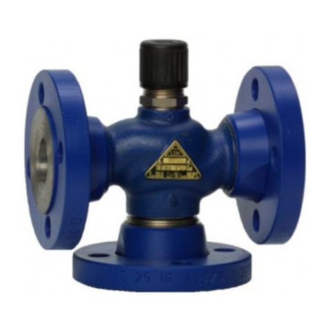
Control valves RV 102 are two-way or three-way valves with threaded connection. Valve body is made of
bronze. Control valves RV 103 are two-way or three-way valves with flanged connection. Valve body is made of
grey cast iron. Flow characteristics, Kvs values and leakage are acc. to international standards.
Valves can be used as : - three-way control valve
- two-way control valve with reversing function
- two-way angular control valve
Valves RV 10x are designed for hand wheel (RV 10x R) or for electric and electrohydraulic actuators as
Siemens (RV 10x EL, HL), Sauter (RV 10x ES, HS), Johnson Controls (RV 10x EC), Honeywell (RV 10x EH),
Belimo (RV 10x EB) and Czech of producers as Ekorex+, ZPANová Paka (RV 10x ER, EN).
1.2 Application
The valves are designed for control circuits PN 16. The valves are accurately designed to regulate pressure and
flow of liquids, gases and steams without abrasive particles as water (except of drinking water ) low-pressure
steam (only RV102) and air. Sort of operating medium has to be compatible with the material body. Acidity,
resp. alkalinity of medium has to be in range from pH 4.5 to pH 9.5. For proper function the producer
recommends to install a filtr into the pipeline in front of the valve .
The valve cannot work in cavitation conditions. RV 103 valves are not suitable for steam and steam
condensate.
1.3 Function
Control Valves serie RV 10x can have equal percentage plug or linear plug. Used actuators allow 3-point
controlling. They can be equipped with the signalization of end positions and transmitters of position.
1.4 Differential pressure
Value Dp is maximum differential pressure when on-off function is always guaranteed. Recommended
max
constant pressure drop should not be higher than 0.6 MPa for valves RV 102. For valves RV 103 pressure drop
should not be higher than 0,4 MPa.
1.5 Valve body specifications
1.
PM - 009/12/01/GB
LDM, spol. s r.o.
Czech Republic
®
RV 102
RV 103
INSTRUCTION FOR INSTALLATION AND MAINTENANCE
CONTROL VALVE
DN 15 - 50 PN 16
Series
Type
Nominal diameter DN
Nominal pressure PN
Body material
Building length
Operating temperature
Connection
Flow characteristic
Kvs values
Leakage
Packing set
RV 102 RV 103
Three-way control valve
Two-way control valve with reversing function
DN 15 - 50
PN 16
Acc. to DIN 3202 - M4
Socket with female thread
Acc. to ÈSN EN ISO 228-1
V - ported
Linear, equal percentage
Class III. acc. to ÈSN EN 1349 (<0.1% Kvs) in way A-AB
O - ring EPDM
Acc. to ÈSN EN 1092-1
Flange with raise face, type B1
Acc. to ÈSN EN 558-1 - F1
3
from 0.6 to 40 m /h
Bronze 42 3135 (CuSn5Pb5Zn5) G EN-JL 1040rey cast iron
Brass 42 3234 (CuZn40Pb2)
Plug material
from 0°C to 150°C
Type of plug
Rangeability 50:1
PM - 009/12/01/GB _ RV 102, 103 1/6

2. DIRECTIONS FOR INSTALLATION
2.
The valves are delivered from the company assembled, adjusted and tested. Before valve´s installation into
pipiline you must check the data on the name-plate with data mentioned in accompanying documentation.
Then check if the valve or the actuator are not damaged and dirty. Pay attention especially to inner spaces and
packing surfaces of valve.
2.2 Dimensions and weights of valves RV 10x
1 Preparation before installation
RV 102
D -with actuators Siemens and
L,B
Belimo
D -with actuators Sauter
S
D -with actuators Johnson Controls
C
D -with actuators Honeywell,Ekorex+
H,E
and ZPA Nová Paka
H - with actuators Siemens, J.Controls,
Honeywell, Belimo, Ekorex+and
ZPA Nová Paka
H -with actuators Sauter
S
RV 102 RV103
DN L1V2
V1HHSDL,B DSDCDH,E m
mm mm mm
mm mm mm mm mm mm mm kg
15
20
25
32
40
50
85
95
105
120
130
150
27
32
41
50
58
70
43
48
53
66
70
80
10 10
16 14
8 M6
M 8x1
0.55
0.65
0.80
1.40
2.00
2.95
1/4´´UNF
C
G 1/2
G 3/4
G 1
G 1 1/4
G 1 1/2
G 2
L1L2L3
9
11
12
14
16
18
mm
12
14
16
18
20
22
S
mm
25
25
25
35
35
42
DN D1D2D3nxd afL1V1V2HHSDL,B DSDCDH,E m
mm mm mm mm mm mm mm mm mm mm mm mm mm mm mm kg
15
20
25
32
40
50
95
105
115
140
150
165
65
75
85
100
110
125
45
58
68
78
88
102
4 x 14
4 x 18
16
18
20
2
3
130
150
160
180
200
230
65
75
80
90
100
115
25
25
25
35
35
42
10 10
16 14
8 M6
M 8x1
3.2
4.3
5.5
7.7
8.5
11.9
1/4´´NF
RV 103 MIX. 2-cest.
m
kg
4.0
5.4
6.8
9.7
10.9
15.6
PM - 009/12/01/GB _ RV 102, 103 2/6

2.3 Installation of valve into pipeline
Valve must be installed into pipeline so that flow of medium is according to arrows on the body. The
actuator can be installed in any position except the position below the valve body. Keep the rules in
instalation and maintenance instructions of actuator too. Protection of actuator against the radiant heat can
be necessary in case of high temperature application. As a basic provision can be made pipeline insulation,
actuator turning aside from vertical position, etc..
For proper function of control valve, below-mentioned instructions must be obeyed :
- no excessive forces can be transfered from pipeline to valve.
- the pipeline must be cleaned from dirt before valve installation.
- the valve can not be installed just behind the bend. Pipeline should be straight min. 6xDN in front of the
valve.
- it is recommended to keep clean space around the valve for easy manipulation and service.
- installation itself must be done precisely. Pipeline flanges must be coaxial with valve flanges.
- it is necessary to use connectioned pipe union for valves with threaded connection during its installation so
that the dismantling of valve from the pipeline will be possible and can be carried out.
2.3.1 Electric actuator or electrohydraulic actuator connection
These work may be carried out by trained personnel only. It is necessary to keep all safety rules relating to
electric machines. Further it is necessary to follow instructions for installation, operation and maintenance of
electric actuators issued by the producer. Position transmitter and signalisation switches, if part of delivery, are
positioned under the actuator cover.
Before valve commissioning, the data, given in the actuator ID plate (especially supply voltage and voltage of
control signal), should be checked/compared with given specification and verify, that the actuator can be
connected to superordinate regulator.
Switching off by torque or power switch is adjusted in upper position for the valves that are equipped only with
the seat in straight way. In position when the straight way is open, the switching the actuator off is adjusted by
limit switch or torque switch with the use of the stop.
In case the actuator is dismantled from the valve body for any reason such as the valve installation into pipeline
etc., it is necessary to check the setting again after the assembly possibly to carry out the complete setting of
actuator again. Producer does not take over the guarantee if the damage was caused by improper setting or
adjusting of the actuator. In case of need, it is possible to ask for such service from service organization of the
producer.
The length of the actuator´s cables shall be selected so that the actuator can be removed from the valve without
disconnection from the terminal board.
2.3.2 Checking after installation
Piping system should be pressured after valve installation and the checked if there is not leak. Check the
packing set tightness as well. Then check the proper function of actuator by doing a few strokes.
2.4 Operating and Maintenance
2.4.1 Packing set
The packing set does not need a lot of servicing in the case that the valve has PTFE or O-ring EPDM packing
set, and also in this case gland bolt may not be tightened nor loosen. If leakage is high, the packing set must be
changed.
2.4.2 Exchange of packing set
If there is need to exchange the packing set because of high leakage, first the actuator must be dismantled and
then the packing screw must be screwed out. The pipeline may not be under pressure during changing of
packing set. After this, there is need to check the state of spindle surface and clean the inside of the packing
box. The surface of spindle must be smooth and not damaged. If necessary, the spindle must be exchanged.
Packing set is filled, by the producer, with a special lubricant acc. to the type of used packing. Such lubricant
ensures the proper function of the packing rings within their service life. The spindle may not be greased
during the operation!
After exchange of packing set, the gland bolt must be tightened to the bottom of packing box.After installation of
actuator, there is necessary to make test as in 2.3.2.
2.4.3 Exchange of plug
When the valve is used for medium with high dirt-content is probability that packing surface of plug will be wear
out and internal leakage of valve will be too high (seat - plug leakage). In this case the professional service must
be called.
Regarding the fact the valve is delivered with its actuator as a complet, the basic adjusting is carried out.
PM - 009/12/01/GB _ RV 102, 103 3/6

2.4.4 Electric actuators
Electric actuators have to be operated according to instructions given in „ Actuator manual ”. In case of
malfunction of actuator, see the instructions or ask for professional repair man.
2.5 Elimination of defects and malfunctions
If a defect is detected on the valve (leakage, leakage of packing or bonnet sealing, etc.), it is necessary to
ensure its repair immediately otherwise a permanent damage may occur to sealing surfaces and other parts
exposed to effects of leaking medium. Prior to any repair work on the valve, make sure that piping system
is free of pressure!
2.5.1 High leakage of valve
High leakage can be caused:
1 - when the valve is used under the higher differential pressure than Dpmax.
2 - by insufficient thrust of actuator. There is need to test the function of actuator again.
3 - by damaged seating faces of plug and seat. In this case the professional service must be called.
2.5.2 High leakage of packing set
In the case of high leakage of the packing set, points 2.4.1. and 2.4.2. must be done or professional service
must be called.
2.6 Spare parts
Spare parts are not part of valve delivery. They must be ordered separately. For the spare parts order, following
data must be written: type of a valve, nominal diameter DN, Serial valve´s number, name of a spare part.
2.7 Guarantee conditions
The producer does not guarantee the operation and safety of the product under conditions different from data
given in the catalogue data sheet. Any using of the valve under different conditions shall be consulted with the
producer. Defects of the valve caused by impurities in process medium shall be considered as out of guarantee
terms. The producer does not take over the guarantee if any change was made by the user without prior written
consent from the producer.
2.8 Waste disposal
Packaging and the valves (after their scrapping) shall be disposed off in the common way, e.g. by handing over
to a specialized company for a disposal (body and metal parts - metal scrap, packaging + other non-metallic
parts - communal waste).
PM - 009/12/01/GB _ RV 102, 103 4/6

1. Valve Control valve
2. Type of valve Valve from bronze - threaded
Valve from grey cast iron - flanged
Electric actuator
Electrohydraulic actuator
Hand wheel
Two-way threaded
Two-way threaded angular
Three-way threaded mixing (distributing)
Two-way flanged
Two-way flanged angular
Three-way flanged mixing (distributing)
5. Body material Grey cast iron
Bronze
6. Flow characteristic Linear
Equal percentage
7. Kvs values Column number acc. to table Kvs values
8. Nominal pressure PN PN 16
9. Operating temperat. °C
10. Nominal diameter DN
XX XXX XXX XX XX XX / XXX - XX
3. Actuator
4. Connection
RV
102
103
EXX
HXX
RXX
1
2
3
4
5
6
3
5
1
2
X
16
140
150
XX
RV 103
RV 102
Valve complete specification No. for ordering RV 10x
Ordering example: Three-way valve DN 25, PN 16, with electric actuator SQX 32.00, body material bronzthreaded
3
connection G 1, linear characteristic, Kvs = 10 m /h, is marked as: RV 102 ELA 3511 16/140-25
Maximum permissible working pressure [MPa]
Temperature [°C]
Material PN
120 150 200 250 300
16
16
Grey cast iron EN-JL 1040
Bronze 42 3135
1.60
1.60
1.44
1.09
1.28
0.73
1.12
-- 0.96
--
PM - 009/12/01/GB _ RV 102, 103 5/6

ADDRESS OF FACTORY
REGIONAL OFFICES
LDM SUBSIDIARIES ABROAD
LDM, spol. s r.o.
Litomyšlská 1378
560 02 Èeská Tøebová
Czech Republic
tel.: +420 465 502 511
fax: +420 465 533 101
E-mail: [email protected]
http://www.ldmvalves.com
LDM Armaturen GmbH
Wupperweg 21
D-51789 Lindlar
Deutschland
tel: +49 2266 440333
fax: +49 2266 440372
mobile: +49 1772960469
Guarantee and after guarantee service provided.
®
LDM, spol. s r.o. reserves the right to modify or improve the designs or specifications of such products at any time without notice
LDM, spol. s r.o.
Office in Ústí nad Labem
Ladova 2548/38
400 11 Ústí nad Labem - Severní Terasa
Czech Republic
tel.: +420 602708257
E-mail: [email protected]
LDM, spol. s r.o.
Office in Prague
Podolská 50
147 01 Praha 4
Czech Republic
tel.: +420 241087360
fax: +420 241087192
E-mail: [email protected]
LDM, Bratislava s.r.o.
Mierová 151
821 05 Bratislava
Slovakia
tel: +421 243415027-8
fax: +421 243415029
http://www.ldm.sk
LDM, Polska Sp. z o.o.
ul. Modelarska 12
40-142 Katowice
Polska
tel: +48 327305633
fax: +48 327305233
mobile: +48 601354999
E-mail: [email protected]
LDM Bulgaria Ltd.
z.k.Mladost 1
bl.42, floor 12, app.57
1784 Sofia
Bulgaria
tel: +359 2 9746311
fax: +359 2 8771344
mobile: +359 888925766
www.ldmvalves.com
SERVICE ORGANIZATION
LDM servis, spol. s r.o.
Litomyšlská 1378
560 02 Èeská Tøebová
Czech Republic
tel: +420 465502411-13
fax: +420 465531010
PM - 009/12/01/GB _ RV 102, 103 6/6
1015
OOO "LDM Promarmatura"
Jubilejniy prospekt, dom.6a, of. 601
141407 Khimki
Moscow Region
Russia
tel.: +7 495 7772238
fax: +7 495 7772238
mobile: +7 9032254333
e-mail: inforus@ldmvalves.com
TOO “LDM”
Shakirova 33/1, kab. 103
100012 Karaganda
Kazachstan
tel.: +7 7212566936
fax: +7 7212566936
mobile: +7 7017383679
e-mail: [email protected]
This manual suits for next models
1
Table of contents
Other LDM Control Unit manuals
Popular Control Unit manuals by other brands

Contec
Contec ADI16-4(FIT)GY manual
MC Crypt
MC Crypt 59 11 57 instruction manual

SPX FLOW
SPX FLOW APV DELTA DKR2 instruction manual
Goldline
Goldline AQL-BASE-RF Installation and operation guide
SPX FLOW
SPX FLOW Power Team A operating instructions
American Flow Control
American Flow Control 2500 Series product manual
