manuals.online logo
Brands
  1. Home
  2. •
  3. Brands
  4. •
  5. LDT
  6. •
  7. Media Converter
  8. •
  9. LDT M-DEC-DC-G User manual

LDT M-DEC-DC-G User manual

L
ittfinski
D
aten
T
echnik (
LDT
)
Operating Instruction
Multi-Digital
4-fold decoder for motor
driven turnouts
with external power supply possibility
from the Digital-Professional-Series !
M-DEC-DC-G
Part-No.:
410413
>> finished module in a case <<
Suitable for the DCC-Format:
e.g. Lenz-, Arnold-, Roco-, LGB-Digital, Intellibox, TWIN-
CENTER, Digitrax, Zimo, Märklin-Digital=, EasyControl,
KeyCom-DC, ECoS, DiCoStation and others
Turnouts can be switched as well via loc-addresses
(e.g. Lokmaus 2® and R3®)
For the digital control of :
⇒Up to four turnout motor drives.
(e.g. drives from Fulgurex, Pilz or Hoffmann/Conrad)
⇒Motor current per output up to 1A.
This product is not a toy! Not suitable for children under 14 years of age!
The kit contains small parts, which should be kept away from children under 3!
Improper use will imply danger of injuring due to sharp edges and tips! Please store
this instruction carefully.
Introduction/Safety instruction:
You have purchased the 4-fold decoder M-DEC-DC for motor
driven turnouts for your model railway as finished module in a
case supplied within the assortment of Littfinski DatenTechnik
(LDT).
We are wishing you having a good time using this product.
The M-DEC-DC (receiver device is marked with a blue dot) is
suitable for the DCC Data format, used for instance within the
systems of Arnold-Digital, Intellibox, Lenz-Digital Plus, Roco-
Digital, TWIN-CENTER, Digitrax, LGB-Digital, Zimo, Märklin-
Digital=, EasyControl, KeyCom-DC, ECoS and DiCoStation.
The decoder M-DEC-DC can not only switch turnouts via the
turnout addresses but also responds to loc-addresses.
Therefore is it possible to shift turnouts with the functional keys
F1 to F4 of the Lokmaus
2® or R3®.
The finished module in a case comes with 24 month warranty.
•Please read the following instructions carefully. Warranty will
expire due to damages caused by disregarding the operating
instructions. LDT will also be not liable for any consequential
damages caused by improper use or installation.
Connecting the decoder to your digital model
railway layout:
•Attention: Before starting any installation switch off all
power supply to the digital layout by pushing the stop
button or disconnect all main supply to the transformers.
The decoder receives the digital information via the clamp KL2.
Connect the clamp directly to the command station or to a
booster assuring the supply of digital information free from any
interference.
The DCC-Digital-Systems uses different colorcodes respectively
indications for the two digital cables. Those markings are
indicated next to the clamp KL2.These markings have not
necessarily to be maintained correct as the decoder converts the
signal automatically to be correct.
The decoder receives the power supply via the two pole clamp
KL1. Voltage within the range of 12…18V~ is acceptable
(alternate current output of a model railway transformer) or
15...24 V= (direct voltage from a switched mode mains power
supply).
If you do not want to supply power to the decoder M-DEC from
an external transformer you can connect the clamp KL1 to
KL2 with two wires. In this case the decoder will get the power
supply complete from the digital system.
Programming the decoder address:
To program the decoder-address a motor driven turnout has to
be connected to the output 1 (clamp KL9) of the decoder.
•Switch on the power supply of your model railway.
•Adjust the speed of all connected speed controller to zero.
•Press the programming key S1.
•The turnout drive connected to output 1 will now move a little
every 1.5 seconds. This indicates that the decoder is in the
programming mode.
•Is the motor not moving is it possible that the motor drive
contains directional diodes. In this case switch off the power
supply and turn around the two connection wires on output 1.
After switching power on the turnout drive should move at a
1.5 second interval.
•Switch now one turnout of a group of four assigned to the
decoder via the keyboard of the control unit or via a remote
control unit.
For programming the decoder address you can also release a
turnout switch signal via a personal computer.
Remarks: The decoder-addresses for magnet accessories
are combined in groups of four. The address 1 to 4 build the
first group. The address 5 to 8 build the second group etc.
Each M-DEC-DC decoder can be assigned to any of these
groups. Which turnout of a group will be activated for the
addressing does not matter.
•If the decoder has recognized the assignment correctly the
connected turnout will move a little faster. Afterwards the
movement slows down to the initial 1.5 seconds again.
•Leave the programming mode by pressing the programming
key S1 again. The decoder address is now permanently
stored but it can be changed at any time by repeating the
programming as described above.
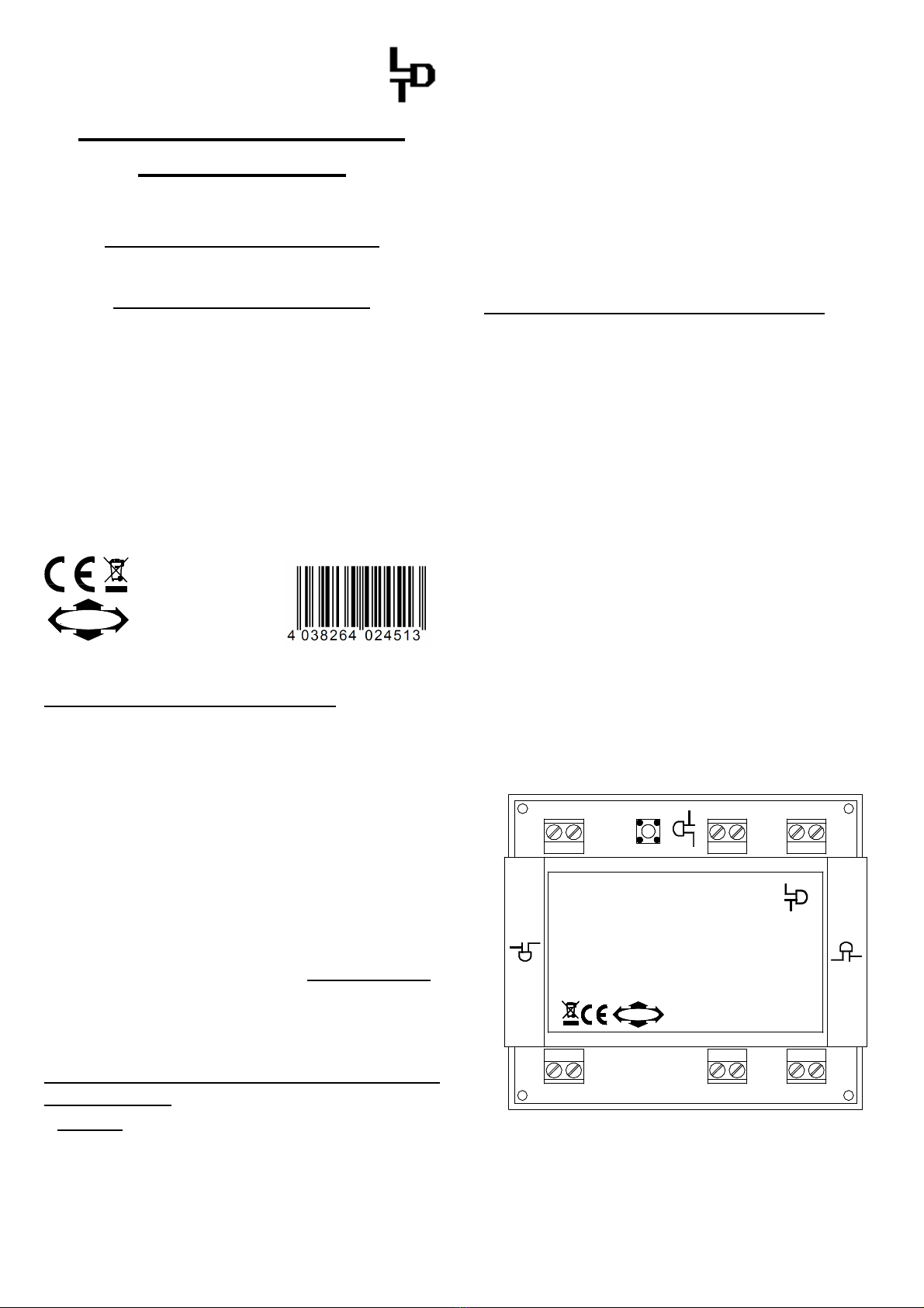
KL2
S1
Littfinski DatenTechnik (LDT)
3
BA
4
BA
red brown
K J
15 ... 24V=
12 ... 18V~
KL1
M-DEC/1-DEC
Rev. 2.0
4-fach Decoder für
motorischeAntriebe
4-fold decoder for
motor driven turnouts
1
BA
2
BA
Decoder für motorische
Antriebe: M-DEC-DC
4-fach Decoder für DCC Digitalsysteme.
Motorstrom: 1 Ampere pro Ausgang.
Multi-Digital
Littfinski DatenTechnik (LDT)
www.ldt-infocenter.com
Digital-Profi werden!
•If you press the first key of the programmed group of keys or
you send a switch signal for this turnout from a PC the
addressed turnout drive should move into the called direction
until end-stop.
Switching turnouts via loc-addresses
(e.g. Lokmaus 2® or R3®):
The decoder M-DEC-DC makes it possible to switch motor driven
turnouts via loc-addresses. For example switching with the
functional keys F1 to F4 of the Lokmaus
2® or R3®.
The function key F1 will shift the drive at the output 1 and the
key F2 will shift the turnout at the output 2 etc.
Each stroke on a function key will shift the respective turnout
from round to straight or vice versa.
Also for programming the loc-addresses a turnout motor-drive
has to be connected to the output 1 of the decoder.
•Switch the power supply of your model rail way on.
•Adjust the speed of all connected speed controller
respectively Lokmauses to zero (center position of the
adjusting dial).
•Press the programming key S1.
•The motor drive connected to output 1 shall move now
automatically every 1.5 seconds. This indicates that the
decoder is in the programming mode.
•Adjust now on one of the Lokmauses the required address
and turn the speed adjusting dial off from the center
position. If the decoder has recognized the assignment
correctly the connected turnout drive will move now a little
faster. The decoder M-DEC-DC will accept loc-addresses
between 1 and 99.
•Adjust the speed now to zero again. The turnout will move
now a little slower.
•Press the programming key S1 again for leaving the
programming mode.
•If you press functional key F1 you can shift the turnout of
the output 1 with each stroke. If there are turnouts
connected on output 2 to 4 of the decoder M-DEC-DC you
can shift the respective registered turnouts with the
programmed loc-addresses with each stroke of the function
keys F2 to F4.
Please attend to the following:
•All 4 decoder outputs can supply a motor current of 1
Ampere. As the moving time of the drives is only some
seconds the tracking time of the decoder output is adjusted
to 10 seconds. This indicates that the respective output will
be switched voltage free 10 seconds after the end of the
switch command. This assures that a defect end-switch will
not destroy a drive with continuous current.
•The motors of turnout drives can create considerable
electromagnetic interference. Normally the decoder
M-DEC will not be influenced by this interference. But in case
the decoder will be influenced please check the turnout drive
installation cables. Those cables should not wrap or cross
the decoder closely. Install the cables that way that they go
straight away from the clamps of the decoder. If limited space
requires a bad installation layout and the function of the
decoder will be disturbed please push about 5 ferrous pearls
onto each motor cable.
These ferrous pearls are available at electronic shops or at
LDT with the order code `FP`.
Another possibility is to solder an interference capacitor
(between 1nF and 10nF) across each motor. Fulgurex drives
need this capacitor in any case.
Sample Connections:
Spannungsversorgung
12 ... 18V~
15 ... 24V=
3
4
1
2
Fulgurex
Pilz/Tillig
M-DEC
Digitalinformationen
(von Steuereinheit oder Booster)
Hoffmann
Conrad
The above draft provides an example how to connect the
different drives directly to the M-DEC-DC without any additional
circuitry.
Further application examples can be found in the Internet on our
Web-Site (www.ldt-infocenter.com) at the section
downloads/sample connections.
Trouble shooting:
What to do if something is not working as described above?
If you have purchased the decoder as a kit please check carefully
all parts and soldered joints.
Here some possible functional errors and possible solutions:
1. During programming of the decoder addresses the motor
moves within 1.5 seconds, but does not confirm the
programming with faster movement by pressing any key.
•Interfered digital information at KL2 respectively
considerable lost of voltage at the tracks or at the
installation! Connect the decoder directly with cables to the
digital control unit or to the booster instead to the tracks.
2. The turnout connected to output 1 will move always at a faster
sequence after activating the programming key S1.
•Start programming the decoder for motor driven turnouts
M-DEC-DC immediately after switching-on the digital
central unit before any loc is traveling on the track.
•Perform a RESET of the digital central unit. All stored data
will be preserved but the address-repeating-memory will
be deleted. For Intellibox and TWIN-CENTER please
switch-on the unit and press the keys GO and STOP
simultaneous until the report “reset” can be red at the
display.
3. The drive moves not until the end switch but stops after a
short movement. The decoder does not show any reaction after
some commands.
•This can happen especially by Fulgurex-drives without
interference capacitor. Solving: solder an interference
capacitor (1nF) directly to the motor connection clamps.
Made in Europe by
Littfinski DatenTechnik (LDT)
Bühler electronic GmbH
Ulmenstraße 43
15370 Fredersdorf / Germany
Phone: +49 (0) 33439 / 867-0
Internet: www.ldt-infocenter.com
Subject to technical changes and errors. 05/2019 by LDT
Arnold, Märklin, Lenz, Digitrax, Roco and Zimo are registered trade marks.

This manual suits for next models

1

Other LDT Media Converter manuals

LDT LS-DEC-DR-F User manual

LDT

LDT LS-DEC-DR-F User manual

LDT SA-DEC-4 User manual

LDT

LDT SA-DEC-4 User manual

LDT SA-DEC-4-DC-B User manual

LDT

LDT SA-DEC-4-DC-B User manual

LDT LS-DEC-DB-F Technical manual

LDT

LDT LS-DEC-DB-F Technical manual

LDT SA-DEC-4-DC-G User manual

LDT

LDT SA-DEC-4-DC-G User manual

LDT Digital Professional Series User manual

LDT

LDT Digital Professional Series User manual

LDT Digital Professional Series User manual

LDT

LDT Digital Professional Series User manual

LDT Digital Professional Series Technical manual

LDT

LDT Digital Professional Series Technical manual

LDT SA-DEC-4-MM-G User manual

LDT

LDT SA-DEC-4-MM-G User manual

LDT LS-DEC-SNCF-F User manual

LDT

LDT LS-DEC-SNCF-F User manual

LDT M-DEC-DC-F User manual

LDT

LDT M-DEC-DC-F User manual

LDT SA-DEC-4-DC-G User manual

LDT

LDT SA-DEC-4-DC-G User manual

LDT LS-DEC-NS-F User manual

LDT

LDT LS-DEC-NS-F User manual

LDT Digital-Professional Series User manual

LDT

LDT Digital-Professional Series User manual

LDT LS-DEC-SNCF-F User manual

LDT

LDT LS-DEC-SNCF-F User manual

LDT Digital-Professional Series User manual

LDT

LDT Digital-Professional Series User manual

LDT LS-DEC Series User manual

LDT

LDT LS-DEC Series User manual

LDT S-DEC-4-DC-G User manual

LDT

LDT S-DEC-4-DC-G User manual

LDT S-DEC-4-DC-G User manual

LDT

LDT S-DEC-4-DC-G User manual

LDT LS-DEC-USA User manual

LDT

LDT LS-DEC-USA User manual

LDT TT-DEC-R User manual

LDT

LDT TT-DEC-R User manual

LDT QS-DEC-II-F User manual

LDT

LDT QS-DEC-II-F User manual

LDT Digital-Professional Series User manual

LDT

LDT Digital-Professional Series User manual

LDT TT-DEC Series User manual

LDT

LDT TT-DEC Series User manual

Popular Media Converter manuals by other brands

ADF Web AXIS HD67177-A1 user manual

ADF Web

ADF Web AXIS HD67177-A1 user manual

PS Audio PerfectWave Transport Owner's reference

PS Audio

PS Audio PerfectWave Transport Owner's reference

Gonset Super 6 Installation and operating instructions

Gonset

Gonset Super 6 Installation and operating instructions

Fermax DECODER VDS quick start guide

Fermax

Fermax DECODER VDS quick start guide

Siko SG62 quick start guide

Siko

Siko SG62 quick start guide

WATANABE WSP-THS instruction manual

WATANABE

WATANABE WSP-THS instruction manual

Hall Research Technologies VHD-180 user manual

Hall Research Technologies

Hall Research Technologies VHD-180 user manual

GRASS VALLEY T2 Application note

GRASS VALLEY

GRASS VALLEY T2 Application note

AVer AVerKey300 quick guide

AVer

AVer AVerKey300 quick guide

LINK-MI LM-HSD3 operating instructions

LINK-MI

LINK-MI LM-HSD3 operating instructions

MTT MS3739IB user manual

MTT

MTT MS3739IB user manual

Flintec KA-1 Technical manual

Flintec

Flintec KA-1 Technical manual

exemys EGW1-IA3-MB user manual

exemys

exemys EGW1-IA3-MB user manual

Massoth eMOTION Melody manual

Massoth

Massoth eMOTION Melody manual

Aputure A810 user manual

Aputure

Aputure A810 user manual

VOLKTEK NGF-762E Quick installation guide

VOLKTEK

VOLKTEK NGF-762E Quick installation guide

Denon COCOON  guide Quick setup guide

Denon

Denon COCOON guide Quick setup guide

Bosch VJT-X20XF-E Installation and operating manual

Bosch

Bosch VJT-X20XF-E Installation and operating manual

manuals.online logo
manuals.online logoBrands
  • About & Mission
  • Contact us
  • Privacy Policy
  • Terms and Conditions

Copyright 2025 Manuals.Online. All Rights Reserved.