LDT LS-DEC Series User manual
Littfinski DatenTechnik (LDT)
Operating Instruction
Light signal decoder
for light-signals with LED
from the Digital-Professional-Series !
LS-DEC-NS-F Part-No.: 515012
>> finished module <<
Suitable for the digital systems:
Märklin-Motorola and DCC
For digital control of:
⇒up to four 3-aspect signals of the Nederlandse
Spoorwegen (NS)
⇒speed sign is illuminated by slow speed
⇒realistic switching from stop (red) via slow speed (yellow) to
proceed (green)
Realistic operation of the signal aspects by implemented
dimming function and dark phase between the switching of
the signal aspects.
This product is not a toy! Not suitable for children under 14 years of age!
The kit contains small parts, which should be kept away from children under 3!
Improper use will imply danger of injuring due to sharp edges and tips! Please
store this instruction carefully.
blue point
Introduction/Safety instruction:
You have purchased the Light signal decoder LS-DEC-NS for your
model railway as a kit or as finished module.
The LS-DEC is a high quality product that is supplied within the Digital-
Professional-Series of Littfinski DatenTechnik (LDT).
We are wishing you having a good time using this product.
The light signal decoder LS-DEC of the Digital-Professional-Series
can be easily operated on your digital model railway.
By using a connector plug bridge you can choose if you want to
connect the decoder to a Märklin-Motorola system or to a digital
system with DCC standard.
The finished module comes with a 2 years limited warranty.
•Please read the following instructions carefully. Warranty will expire
due to damages caused by disregarding the operating instructions.
LDT will also not be liable for any consequential damages caused by
improper use or installation.
Connecting the decoder to your digital model railway
layout:
•Attention: Before starting the installation-work switch off the
layout voltage supply (switch-off the transformers or disconnect
the main supply).
The Light signal decoder LS-DEC is suitable for the DCC data format
as used e.g. by Lenz-Digital Plus, Roco-Digital (switching via
Keyboard or multiMAUS only; switching via Lokmaus 2® and R3® is
not possible), Zimo, LGB-Digital, Intellibox, TWIN-CENTER, ECoS,
EasyControl, KeyCom-DC and Arnold-Digital / Märklin-Digital=
whenever no connector plug bridge is inserted in position J2.
The decoder is suitable for Märklin-Digital~ / Märklin Systems or
Märklin-Motorola (e.g. Control-Unit, Central Station, Intellibox,
ECoS, EasyControl, KeyCom-MM) if you insert a connector plug
bridge on J2.
The decoder receives the digital information via the clamp KL2.
Connect the clamp with a rail or even better connect the clamp directly
to the command station or a booster assuring the supply of digital
information free from any interference.
Please attend to the marking on clamp KL2. The colors 'red' and
'brown' next to the clamp are usually used by Märklin-Motorola
systems (e.g. Märklin-Digital~ / Märklin Systems / Intellibox).
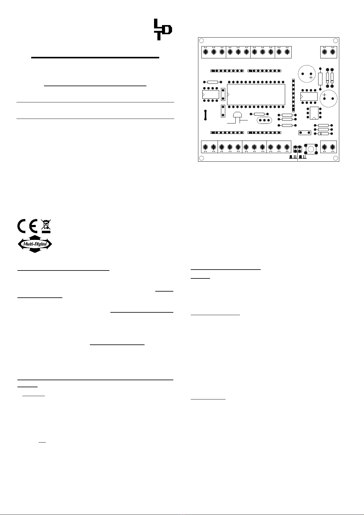
D3 C3
C7
R1
4N25
IC3
R13
J1
CR1
24C01
IC2
L1
C5 C4
Z86E3016
C6
R2 R6
R4
R3
R8
R7
R12
R9
R11
R10
J2
S1
D2
KL6
LM2574
IC4
D1
KL5 KL3KL7
KL8KL9KL10
KL2
KL4
KL1
AK DCCMM
A B Rev. 3.2
Littfinski DatenTechnik (LDT)
br.
rot
LS-DEC
Lichtsignal-Decoder
ws
ge
gn
rt2
rt1
gn2
gn1
ge2
ge1
+
5V
-
ws
ge
gn
rt2
rt1
gn2
gn1
ge2
ge1
+
5V
-
14..18V~
J
K
BR1
Lenz-Digital systems are using the letters 'J'and 'K'.
In case you assemble the decoder to an Arnold-Digital (old)-or
Märklin-Digital= system, you have to connect 'black' to 'K' and 'red' to
'J'.
The decoder receives the power supply via the two poles clamp KL1.
The voltage shall be in a range of 14..18V~ (alternate voltage output of
a model rail road transformer).
If you do not want to supply voltage separately from a transformer to
the LS-DEC decoder you can shorten the clamp KL1 and KL2 with
two wires. In this case the decoder will get the power supply
completely from the digital network.
Connecting the signals:
General:
Up to 4 signals can be connected to the light signal decoder LS-
DEC.Two signals per each 11poles clamp block. The build up of the
two clamps is identical. The following description refers mainly to one
clamp only. As you can see on the identical marking the description is
also valid for the second clamp.
Common connection:
All LED-signals of any manufacturer are designed in accordance to the
same principle. One wire of all light emitting diodes of a signal will be
generally connected to a common cable. Depending if all anodes or all
cathodes are connected together the signals will be called as common
anodes-respectively common cathodes-signal.
If you use signals with common anodes (as most signals) you have to
clamp this cable to the connection marked '+'. In addition you shall not
insert the connection plug bridge in J1 in this case.
If you use signals with common cathodes you have to clamp this cable
to the connection marked '-'. In addition you shall insert the
connection plug bridge in J1 in this case.
The second connection of each light diode is separated and mostly
color marked at the end and contains a series resistor.
Series resistor:
Light diodes have always to be operated with a suitable series
resistor to prevent that they will be destroyed. For this prevention all
outputs have already a series resistor of 330 Ohm integrated on the
printed circuit board of the light signal decoder LS-DEC. Is there no
further external resistor the diode-current will be about 10mA.
This provides sufficient brightness. In case your light diodes are to
bright you can correct the brightness by assembling additionally the
series resistors supplied by the signal manufacturer.
For assigning the single cables of the light diodes to the correct
clamp connection please attend to the below signal images. The
marks next to signal light diodes are not corresponding to the actual
light color but to the marking of the connection at the light signal
decoder LS-DEC.

3-aspect signal of the Nederlandse Spoorwegen (NS)
with illuminated numeric sign:
GN
GE
RT1
RT2
GN1
GE1
GE2
GN2
first signal second signal
train stop train stop
red red red red
1234
green green green green
proceed slow approach proceed slow approach
2-aspect signal of the Nederlandse Spoorwegen (NS):
GN
RT1
GN1
GE2
first signal second signal
train stop train stop
red red red red
1234
green green green green
proceed proceed
If you do not know the correct allocation of the single wires to the light
emitting diodes you can test the function by connecting the wires to
clamp RT1 or GE2. These outputs are active because the decoder
switches all signals to red after switching on.
Further sample connections are available at the internet on our Web-
Site (www.ldt-infocenter.com) under "Downloads". Please load the file
"LSDEC-NS_INFO_engl" onto your PC.
Programming the decoder address:
•Switch on the power supply of your model rail way.
•Activate the programming key S1. Do not touch the integrated
circuits of the pc-board because any electrostatic discharge can
destroy the IC`s.
•At least two light emitting diodes on a signal connected to the
left clamp block will be automatically switched over every 1,5
seconds in a flashing mode. This indicates that the decoder is in
the programming mode.
•Press now one key of the key-group to be assigned to the left
clamp block of the decoder. For programming the decoder address
you can also release a turnout switch signal via a personal
computer.
Remarks: The decoder addresses for magnet accessories also
to be used for the signal-aspects are combined into groups of
four. The address 1 to 4 build the first group. The address 5 to 8
build the second group etc. Each clamp block of a LS-DEC decoder
can be assigned to any of these groups. It does not matter which of
the eight possible keys used for programming will be activated. The
decoder stores always the complete group of keys.
•If the decoder has recognized the assignment correctly the
connected light emitting diode will flash a little faster. Afterwards
the flashing slows down to the initial 1,5 seconds again.
In case the decoder will not recognize the address it could be that
the two digital information connections (clamp2) are wrong
connected. For testing this, switch off the power supply, exchange
the connection on KL2 and start addressing again.
•Press now the programming key S1 again. At least two light
emitting diodes connected to the right clamp block will flash now.
Repeat the programming as described above.
•Now press the programming key S1 a third time for leaving the
programming mode. All signals will be automatically switched to
STOP.
Signal switching:
Below the drafts of the above signal aspects you can find a respective
key-group for the addresses 1 to 4 and the corresponding keys 'red'
and 'green'. Additionally is the meaning of the signal position indicated
above or below. The addresses 1 to 4 are indicated as a sample only.
The actual addresses are corresponding to the assignment of the clamp
bar you choose during programming. The draft regards to one
respective clamp bar only. As both clamp bars are built up identical you
can connect 4 signals to one decoder.
If e.g. the first home signal stays on red you can switch with address 1
and the key green the exit signal to proceed.
The light emitting diode marked with GN will now indicate this at the
signal.
You can observe the switching of the signal aspects from stop (red) via
slow approach (yellow) to proceed (green) as usual for Nederlandse
Spoorwegen signals.
If you use signals with illuminated numerical signs this sign will be
illuminated together with the yellow light emitting diode for slow
approach.
Accessory:
For easy assembly of the printed circuit board below your model rail
road base plate we offer a set of assembly material under the order
identification: MON-SET. Under LDT-01 you can purchase a low price
durable case for the LS-DEC.
Attention:
The Light signal decoder LS-DEC switches the signal aspect not just
on and off but is dimming the light emitting diodes realistic up and
down. Even between the signal aspects a short off-phase is provided.
Further digital commands received during this switch-over-time of about
0,4 seconds will not be taken up from the decoder. Please take care
that the switching-commands are not in a to fast sequence. The
impression is absolutely realistic if the switching is considerable slow.
Made in Europe by
Littfinski DatenTechnik (LDT)
Kleiner Ring 9
D-25492 Heist/Germany
Phone: 0049 4122 / 977 381
Fax: 0049 4122 / 977 382
Internet: http://www.ldt-infocenter.com
Subject to technical changes and errors. 08/2006 by LDT
Märklin and Motorola are registered trade marks.
This manual suits for next models
2
Other LDT Media Converter manuals

LDT
LDT LS-DEC-CFL-F User manual

LDT
LDT TT-DEC Series User manual

LDT
LDT M-DEC-DC-G User manual

LDT
LDT Digital-Professional Series User manual

LDT
LDT SA-DEC-4-DC-G User manual

LDT
LDT SA-DEC-4 User manual

LDT
LDT SA-DEC-4-DC-G User manual

LDT
LDT TT-DEC-R User manual

LDT
LDT LS-DEC-NS-F User manual

LDT
LDT LS-DEC-USA User manual

LDT
LDT Digital-Professional Series User manual

LDT
LDT M-DEC-MM-F User manual

LDT
LDT LS-DEC-DB-F Technical manual

LDT
LDT SA-DEC-4-DC-B User manual

LDT
LDT M-DEC-DC-F User manual

LDT
LDT QS-DEC-II-F User manual

LDT
LDT LS-DEC-DR-F User manual

LDT
LDT SA-DEC-4-MM-G User manual

LDT
LDT S-DEC-4-DC-G User manual

LDT
LDT LS-DEC-CSD-F User manual


