manuals.online logo
Brands
  1. Home
  2. •
  3. Brands
  4. •
  5. LDT
  6. •
  7. Media Converter
  8. •
  9. LDT QS-DEC-II-F User manual

LDT QS-DEC-II-F User manual

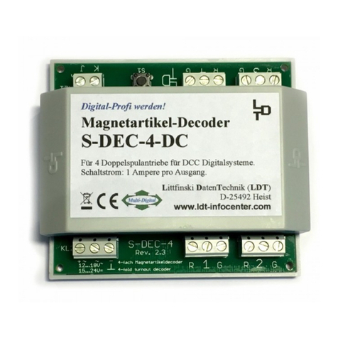
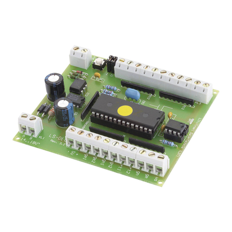
Littfinski DatenTechnik (LDT)
Operating Instruction
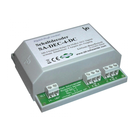
4-fold turnout decoder
from the Digital-Professional-Series !
QS-DEC-II-FPart-No.: 810712
>> finished module <<
Compatible to Märklin-Motorola Format:
(e.g.Märklin-Digital~, Märklin Systems, Intellibox,
EasyControl, ECoS, KeyCom-MM, DiCoStation)
For digital control of:
⇒up to 4 twin-coil magnet accessories
(e.g. turnouts or signals of M-, K-and C-rails)
⇒up to 8 single-coil magnet accessories
(e.g. uncoupling tracks of M-, K-and C-rails)
⇒up to 4 permanent power switch units [DSU]
(e.g. road-/house-illumination and turnout lights)
This product is not a toy! Not suitable for children under 14 years of age!
The kit contains small parts, which should be kept away from children under 3!
Improper use will imply danger of injuring due to sharp edges and tips! Please
store this instruction carefully.
Introduction/Safety instruction:
You have purchased the 4-fold turnout decoder QS-DEC-II for
your model railway as a kit or as finished module.
The QS-DEC-II is a high quality product that is supplied within
the Digital-Professional-Series of Littfinski DatenTechnik
(LDT).
We wish you having a good time using this product.
The turnout decoder QS-DEC-II of the Digital-Professional-
Series can be easily operated on your digital model rail way.
The finished module comes with 24 month warranty.
•Please read the following instructions carefully. Warranty will
expire due to damages caused by disregarding the operating
instructions. LDT will also be not liable for any consequential
damages caused by improper use or installation.
Connecting the decoder to your digital
model railway layout:
•Attention: Before starting the installation switch off the
drive voltage by pushing the stop button from the
command station or disconnect the main supply.
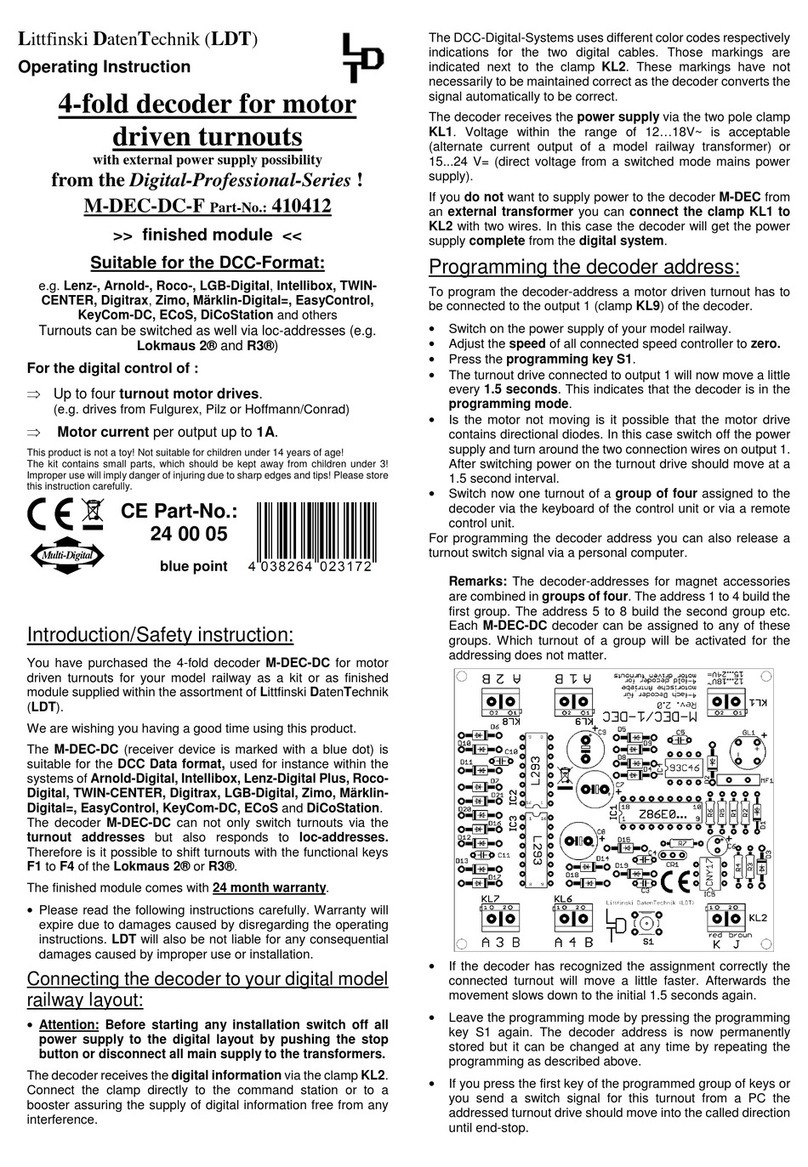
The decoder receives the power supply and the required
digital information via the two pole clamp (KL1). Connect
the clamp with a rail or even better connect the clamp directly
to the command station (e.g. Control Unit or Intellibox)
assuring the supply of digital information free from any
interference.
The cable (red and brown according to Märklin color code)
shall be connected as per marking on the pc-board next to the
clamp.
Now connect turnouts, signals, uncoupling tracks or the
permanent power switch unit [DSU] to the 3-pole clamp
marked 1 to 4.
The yellow common conductor has to be connected always to
the middle clamp of the relevant decoder output clamp. The
two remaining blue cables of a turnout marked with a red plug
(turnout round) and a green plug (turnout straight) shall be
connected to the clamps as marked accordingly.
ULN2003
IC2
ULN2003
IC3
KL3
S1C3
C5
C4
93C06
IC4
Z86E0408
IC1
C1
C2
BC547
C
BE
T1
CR1
D2
D1
R6
KL4
R2
R1
R3
R4
R5
KL1
KL5
KL2
Ver. 3.0
QS-DEC-II
4fach Magnetartikel-Decoder
Peter Littfinski DatenTechnik
Rot Rot Rot
Rot
Gruen Gruen Gruen
Gruen
1 2 3
4
Braun Rot
Programming the decoder address:
To program the decoder address a turnout has to be
connected to the output 1 of the decoder.
•Switch on the power supply on the central unit of your
model rail way with Go.
•Press the programming key S1. Do not touch the integrated
circuits of the pc-board because any electrostatic discharge
can destroy the ICs.
•The turnout connected to output 1 will move now
automatically every 1,5 seconds. This indicates that the
decoder is in the programming mode.
•Press now one push button of the group of four assigned
to the decoder on the Märklin-KEYBOARD or on a
SWITCHBOARD. For programming the decoder address
you can also release a turnout switch signal via a personal
computer which is connected to an INTERFACE.
Remarks:
The 16 pair of keys on each KEYBOARD are divided into 4
groups with 4 keys each. Key 1 to 4 builds the first group,
key 5 to 8 the second etc. Each decoder can be assigned to
any of theses groups. Which key of the wanted block has
been pressed does not matter. The decoder is
programming generally the complete block of four.
•If the decoder has recognized the assignment correctly the
connected turnout will move a little faster. Afterwards the
movement slows down to the initial 1,5 seconds again.
•Leave the programming mode by pressing the
programming key S1 again. The decoder address is now
permanently stored but it can be changed at any time by
repeating the programming as described above.
•If you press the red first key of the programmed group of
keys the addressed turnout should move into the called
direction either into round or by pressing the green key into
straight position. In case the movement goes the wrong
way please exchange the two turnout connection cables at
the ‚G‘reen (straight) and ‚R‘ed (round) marked connection
clamps of the decoder output 1.
Please attend to the following:
•The end switches of the turnout drives on K-and C-tracks
can initiate considerable electromagnetic interference. In

case this interferences disturbs the function of your
decoder please push about 10 ferrite pearls onto the yellow
wire of the turnout. These ferrite pearls are available at
most electronic component dealers or directly from us
under the order description 'FP'(100 pieces in a bag).
•Turnout illumination: The illumination of the M-Track
turnouts is connected to the turnout drive. To safe
expensive digital current Märklin recommends the supply of
the turnout illumination separate from the drive current. The
decoder QS-DEC-II considers this requirement and
provides no current to the turnout lights. If you want to use
separate current supply to the turnout illumination please
proceed as follows: cut the yellow cable between turnout
coil and turnout illumination. Connect a yellow cable
between turnout light and transformer light output. For
more realistic impression you can switch the turnout
illumination by using our permanent power switch unit
[DSU] or our switch decoder SA-DEC-4-MM.
•The outputs 1,2 and 3 are amplified and are able to switch
a load up to 1 Amp. For example is it possible to switch 2
turnouts or 1 turnout and one signal at the same time with
one output. The output 4 can cover a load up to 0,5 Amp.
Decoder application:
The following draft provides some examples of the
multipurpose of the decoder QS-DEC-II.
Besides the typical use as turnout control you can use the
decoder for uncoupling tracks or signal controls.
Com R
G
DSU
Rev. 3.0
Littfinski DatenTechnik
KL2 KL1
KL3
Relais
signal
permanent power switch unit (DSU)
for illumination etc. up to 2x 2A
from light-
transformer
illumination
turnout
uncoupler
M-, K- or C-Gleise power supply and
digital information
QS-DEC-II
4
3
2
1
With our permanent power switch unit [DSU] which includes a
bistable relay is it possible to switch lights or other consumers
up to 4Amp digital via KEYBOARD, SWITCHBOARD or
INTERFACE on or off.
Automatic circuits within the digital system:
7555
reedcontact
4
3
2
1
QS-DEC-II
red
brown
M-, K-or C-tracks
signal
If you want to perform a digital or conventional operation of a
magnet accessory e.g. simple automatic controls please
attend to the draft above.
In this draft the signal will be digitally switched to 'GO'and
digitally or with a reed contact switched to 'HOLD'. Therefore is
it possible that a train coming from the right, which is equipped
with a magnet, will switch the signal to 'HOLD'and indicates a
block control.
If you connect one wire of the reed contact with the decoder
output marked 'red'and the second wire of the reed contact as
indicated with the anode of diode D2 of the decoder QS-DEC-II
the reed contact will also switch the signal to 'HOLD'.
All decoders from the Digital-Professional-Series are 100%
compatible with the extended Motorola-Digital format and can
therefore easy and without any difficulties installed to your
Märklin digital railway.
Further products from the Digital-
Professional-Series:
S-DEC-4-MM
4-fold turnout decoder for up to 4 magnet accessories with
self-learning decoder addresses and separate power supply.
SA-DEC-4-MM
4-fold switch decoder with 4 bistable relays of up to 4 Amp.
each. With self-learning decoder addresses.
M-DEC-MM
4-fold decoder for motor driven turnouts. For motor current
of max. 1A. With self-learning decoder addresses. Drives can
be connected directly to the decoder.
RM-88-N
16-fold feedback module with 16 inputs for the s88 feedback
bus.
RM-88-N-O
16-fold feedback module with 16 galvanic separated opto-
coupler inputs for the s88 feedback bus.
RM-GB-8-N
8-fold feedback module with integrated occupancy detectors
for the s88 feedback bus.
LS-DEC
Light signal decoder for realistic digital switching of 2-or 3-
aspects signals or up to two 7-aspects signals (home signal
and advance signal on one pole).
All components can be purchased as easy to assemble
complete kits, as finished modules or as ready finished
modules in a case.
Made in Europe by
Littfinski DatenTechnik (LDT)
Kleiner Ring 9
D-25492 Heist/Germany
Phone: 0049 4122 / 977 381
Fax: 0049 4122 / 977 382
Internet: http://www.ldt-infocenter.com
Subject to technical changes and errors. 03/2014 by LDT
Märklin and Motorola are registered trade marks.

This manual suits for next models

1

Other LDT Media Converter manuals

LDT LS-DEC-CFL-F User manual

LDT

LDT LS-DEC-CFL-F User manual

LDT S-DEC-4-DC-G User manual

LDT

LDT S-DEC-4-DC-G User manual

LDT LS-DEC-USA User manual

LDT

LDT LS-DEC-USA User manual

LDT M-DEC-DC-F User manual

LDT

LDT M-DEC-DC-F User manual

LDT SA-DEC-4-DC-G User manual

LDT

LDT SA-DEC-4-DC-G User manual

LDT Digital-Professional Series User manual

LDT

LDT Digital-Professional Series User manual

LDT LS-DEC-SNCF-F User manual

LDT

LDT LS-DEC-SNCF-F User manual

LDT LS-DEC-DR-F User manual

LDT

LDT LS-DEC-DR-F User manual

LDT LS-DEC-DB-F Technical manual

LDT

LDT LS-DEC-DB-F Technical manual

LDT M-DEC-MM-F User manual

LDT

LDT M-DEC-MM-F User manual

LDT S-DEC-4-DC-G User manual

LDT

LDT S-DEC-4-DC-G User manual

LDT LS-DEC-NS-F User manual

LDT

LDT LS-DEC-NS-F User manual

LDT M-DEC-DC-G User manual

LDT

LDT M-DEC-DC-G User manual

LDT Digital Professional Series Technical manual

LDT

LDT Digital Professional Series Technical manual

LDT TT-DEC Series User manual

LDT

LDT TT-DEC Series User manual

LDT TT-DEC-R User manual

LDT

LDT TT-DEC-R User manual

LDT Digital Professional Series User manual

LDT

LDT Digital Professional Series User manual

LDT Digital-Professional Series User manual

LDT

LDT Digital-Professional Series User manual

LDT S-DEC-4-MM-B User manual

LDT

LDT S-DEC-4-MM-B User manual

LDT LS-DEC-CSD-F User manual

LDT

LDT LS-DEC-CSD-F User manual

LDT SA-DEC-4-DC-B User manual

LDT

LDT SA-DEC-4-DC-B User manual

LDT LS-DEC-SNCF-F User manual

LDT

LDT LS-DEC-SNCF-F User manual

LDT SA-DEC-4 User manual

LDT

LDT SA-DEC-4 User manual

LDT Digital-Professional Series User manual

LDT

LDT Digital-Professional Series User manual

Popular Media Converter manuals by other brands

Lenz Digital plus LE1014A Information

Lenz

Lenz Digital plus LE1014A Information

PR electronics 3103 product manual

PR electronics

PR electronics 3103 product manual

HEIDENHAIN TTR ERM 2200 C Mounting instructions

HEIDENHAIN

HEIDENHAIN TTR ERM 2200 C Mounting instructions

HAI 32A32-1 manual

HAI

HAI 32A32-1 manual

Lynx C AD 3321 D Reference manual

Lynx

Lynx C AD 3321 D Reference manual

StarTech.com SAT32MSAT257 user guide

StarTech.com

StarTech.com SAT32MSAT257 user guide

Foxun SX-SDH1 operating instructions

Foxun

Foxun SX-SDH1 operating instructions

Extron electronics NAV E 511 user guide

Extron electronics

Extron electronics NAV E 511 user guide

CAMBOARD Extron Electonics YCV 100 user manual

CAMBOARD

CAMBOARD Extron Electonics YCV 100 user manual

Extron electronics Scan Converter VSC 500 Specifications

Extron electronics

Extron electronics Scan Converter VSC 500 Specifications

Ratoc Systems U2SCX-LVD user guide

Ratoc Systems

Ratoc Systems U2SCX-LVD user guide

LH Technologies LH 500 Operator's manual

LH Technologies

LH Technologies LH 500 Operator's manual

Matrox 6150 Encoder user guide

Matrox

Matrox 6150 Encoder user guide

TRENDnet TFC-110MSC - DATA SHEETS datasheet

TRENDnet

TRENDnet TFC-110MSC - DATA SHEETS datasheet

Matrox Maevex 6152 Series user guide

Matrox

Matrox Maevex 6152 Series user guide

LAWO V_pro8 Installation & operation manual

LAWO

LAWO V_pro8 Installation & operation manual

San Telequip SC12FPIA manual

San Telequip

San Telequip SC12FPIA manual

M-system 18TS instruction manual

M-system

M-system 18TS instruction manual

manuals.online logo
manuals.online logoBrands
  • About & Mission
  • Contact us
  • Privacy Policy
  • Terms and Conditions

Copyright 2025 Manuals.Online. All Rights Reserved.