LDT S-DEC-4-DC-G User manual

Littfinski DatenTechnik (LDT)
Operating Instruction
4-fold turnout decoder
with possible external power supply
from the Digital-Professional-Series !
S-DEC-4-DC-G Part-No.: 910213
>> finished module in a case <<
Compatible to the DCC-Format:
(e.g. Lenz Digital Plus, Arnold-, Märklin-Digital=, Intellibox,
TWIN-CENTER, Roco-Digital, EasyControl, ECoS,
KeyCom-DC, Digitrax, DiCoStation, Zimo and others)
(switching of turnouts via Lokmaus 2® and R3® is possible)
For digital control of:
⇒up to 4 twin-coil magnet accessories
(e.g. turnouts or semaphore-signals).
⇒up to 8 single-coil magnet accessories
(e.g. uncoupling tracks).
⇒up to 4 permanent power switch units [DSU]
(e.g. illumination).
This product is not a toy! Not suitable for children under 14 years of age!
The kit contains small parts, which should be kept away from children under 3!
Improper use will imply danger of injuring due to sharp edges and tips! Please
store this instruction carefully.
Introduction/Safety instruction:
You have purchased the 4-fold turnout decoder S-DEC-4-DC
for your model railway supplied within the assortment of
Littfinski DatenTechnik (LDT).
We are wishing you having a good time using this product.
The S-DEC-4-DC is suitable for the DCC Data format, as used
for instance at the systems of Lenz-Digital Plus, Arnold-,
Märklin-Digital=, Intellibox, TWIN-CENTER, Roco-Digital,
EasyControl, ECoS, KeyCom-DC, Digitrax, DiCoStation and
Zimo.
The decoder S-DEC-4-DC can not only switch turnouts via the
turnout addresses but also responds to loc-addresses.
Therefore is it possible to shift turnouts with the keysF1 to F4 of
the Lokmaus 2® or R3®.
The decoder S-DEC-4-DC is multi digital and can be installed
to the Intellibox and on TWIN-CENTER without any problems.
The decoder comes with 24 month warranty.
•Please read the following instructions carefully. Warranty will
expire due to damages caused by disregarding the operating
instructions. LDT will also be not liable for any consequential
damages caused by improper use or installation.
Connecting the decoder to your digital
model railway system:
•Attention: Before starting the installation switch off the
drive voltage by pushing the stop button or disconnect
the main supply to all transformers.
The decoder receives the digital information via the clamp
KL1. Connect the clamp directly to the command station or to a
booster assuring the supply of digital information free from any
interference.
The DCC-Digital-Systems uses different color codes
respectively indications for the two digital cables. Those
markings are indicated next to the clamp KL1.These markings
have not necessarily to be maintained correct as the decoder
converts the signal automatically to be correct.
The decoder receives the power supply via clamp KL2 (middle
and left clamp marked with ~). Voltage in the range of 14 to
18V~ is acceptable (alternate current output of a model railway
transformer).
If you do not want to supply power to the decoder S-DEC-4-DC
from an external transformer you can connect the clamp
KL1 to KL2 with two wires. In this case the decoder will get the
power supply complete from the digital system.
Now connect turnouts, signals, uncoupling tracks or the
permanent power switch units [DSU] to the 3-pole clamp
marked 1 to 4.
The common conductor of a double coil (turnout or semaphore
signal) has always to be connected to the middle clamp of the
relevant decoder output. The two remaining cables mostly
marked with red (turnout round) and green (turnout straight)
shall be connected to the clamps marked ‚R‘ and ‚G‘
accordingly.
Programming the decoder addresses:
To program the decoder address a turnout has to be connected
to the output 1 of the decoder.
•Switch on the power supply of your model rail way.
•Adjust the speed of all connected speed controller to zero.
•Press the programming key S1.
The turnout connected to output 1 will move now automatically
every 1,5 seconds. This indicates that the decoder is in the
programming mode.
L
ittfinski
D
aten
T
echnik
D-25492 Heist
www.ldt-infocenter.com
S1
KL1
Red
J
Black
K red brown
4fach Weichendecoder
Accessory Decoder
KL2
14 .. 18V
Littfinski DatenTechnik (LDT)
1RG2RG
3RG4RG
S-DEC-4
Rev. 2.1
~ ~
Digital-Profi werden!
Für 4 Doppelspulenantriebe für DCC Digitalsysteme.
Schaltstrom: 1 Ampere pro Ausgang.
Magnetartikel-Decoder
S-DEC-4-DC
Multi-Digital
•Switch now one turnout of the group of four assigned to
the decoder via the keyboard of the control unit or via a
remote control. For programming the decoder address you
can also release a turnout switch signal via a personal
computer.
Remarks: The decoder addresses for magnetic accessories
are combined into groups of four. The address 1 to 4 build
the first group. The address 5 to 8 build the second group
etc. Each S-DEC-4-DC decoder can be assigned to any of
these groups. Which turnout of a group will be activated for
the addressing does not matter.
•If the decoder has recognized the assignment correctly the
connected turnout will move a little faster. Afterwards the
movement slows down to the initial 1,5 seconds again.
•Leave the programming mode by pressing the programming
key S1 again. The decoder address is now permanently
stored but it can be changed at any time by repeating the
programming as described above.
•If you press the first key of the programmed group of keys or
you send a switch signal for this turnout from a PC the
addressed turnout should move into the called direction
either into round or into straight. In case the movement goes
the wrong way please exchange the two turnout connection
cables at the ‚G‘reen (straight) and ‚R‘ed (round) marked
connection clamps of the decoder output 1.
Switching turnouts via loc-addresses
(e.g. Lokmaus 2® or R3®):
The decoder S-DEC-4-DC makes it possible to switch turnouts
via loc-addresses. For example switching with the functional
keys F1 to F4 of the Lokmaus 2® or R3®.
The function key F1 will shift the turnout at the output 1 and
the key F2 will shift the turnout at the output 2 etc.
Each stroke on a function key will shift the respective
turnout from round to straight or vice versa.
Also for programming the loc-addresses a turnout-drive has to
be connected to the output 1 of the decoder.
•Switch on the power supply of your model rail way.
•Adjust the speed of all connected speed controller
respectively Lokmauses to zero (center position of the
adjusting dial).
•Press the programming key S1. Do not touch the
integrated circuits of the pc-board because any electrostatic
discharge can destroy the IC`s.
•The turnout connected to output 1 will move now
automatically every 1,5 seconds.This indicates that the
decoder is in the programming mode.
•Adjust now on one of the Lokmauses the required address
and turn the speed adjusting dial off from the center
position. If the decoder has recognized the assignment
correctly the connected turnout will move a little faster.
The decoder S-DEC-4-DC will accept loc-addresses
between 1 and 99.
•Adjust the speed now to zero again. The turnout will move
now a little slower.
•Press the programming key S1 again for leaving the
programming mode.
•If you press functional key F1 you can shift the turnout of
the output 1with each stroke. If there are turnouts
connected on output 2 to 4 of the decoder S-DEC-4-DC you
can shift the respective registered turnouts with the
programmed loc-addresses with each stroke of the function
keys F2 to F4.
Please attend to the following:
•All 4 decoder outputs can switch a current of 1 Ampere
peak. Modern turnout drives need about 0,25 up to 0,5
Ampere. Older drives which are not free moving or which
are dirty need more Ampere. The S-DEC-4 Decoder is
protected against overload caused by drives which are
not switching off at the end movement. The protector is an
automatic fuse which will switch back into normal operation
a few seconds after the load current is below maximum
value.
•Turnouts with integrated end-switch can create
considerable electromagnetic interference. Normally the
decoder S-DEC-4will not be influenced by this interference.
But in case the decoder will be influenced please check the
turnout installation cables. Those cables should not wrap
or cross the decoder closely. Install the cables that way that
they go straight away from the clamps of the decoder.
If limited space requires a bad installation layout and the
function of the decoder will be disturbed please disconnect
the middle cable of each turnout connection and push about
5 to 10 ferrous pearls onto this cable before connecting to
the clamp again.
•These ferrous pearls are available at electronic shops or at
LDT with the order code `FP`.
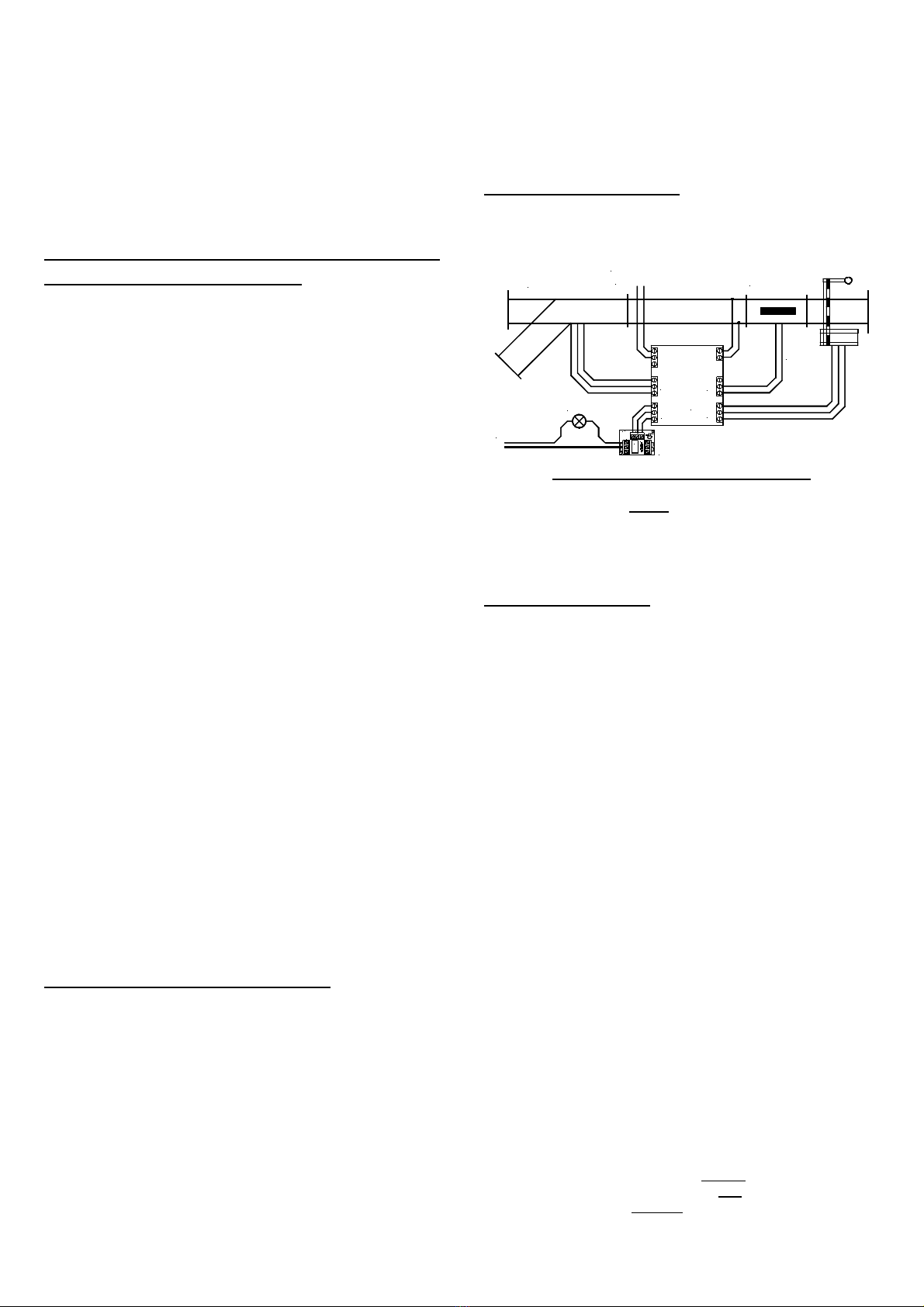
Decoder application:
Besides the typical application of turnout control the decoder
S-DEC-4-DC can also be used for uncoupling tracks and
semaphore-signals.
14..18V~
Com RG
DSU
Rev. 3.0
Littfinski DatenTechnik
KL2 KL1
KL3
Relais
1
23
4
S-DEC-4
uncoupler
transformer
turnouts
lights
from
transformer
signals
permanent power switch unit (DSU)
for lights or other consumers up to 2x 2A
With our permanent power switch unit [DSU], which is
equipped with a bi-stable relay is it possible to switch lights or
other consumers up to 4Amp digital on or off.
Further application and circuit examples can be found in the
Internet on our Web-Site (www.ldt-infocenter.com) at the
section downloads and sample connections.
Trouble shooting:
What to do if something is not working as described above?
Here some possible functional errors and possible solutions:
1. During programming of the decoder addresses the
turnout moves within 1,5 seconds, but does not confirm the
programming with faster movement by pressing any key.
•Interfered digital information at KL1 respectively
considerable lost of voltage at the tracks or at the
installation! Connect the decoder not to tracks but directly
with cables to the digital control unit or to the booster
instead to the tracks. Increase the cable diameter for long
distances.
•Eventually the clamps have been tightened to strong and
therefore the clamps got loose at the soldering to the pc
board. Check the soldering connection of the clamps at
the lower side of the pc-board and re-solder them if
required.
2. The turnout connected to output 1 will move always at a
faster sequence after activating the programming key S1.
•Start programming the turnout decoder S-DEC-4-DC
immediately after switching-on the digital central unit
before any loc is traveling on the track.
•Perform a RESET of the digital central unit. All stored data
will be preserved but the address-repeating-memory will
be deleted. For Intellibox and TWIN-CENTER please
switch-on the unit and press the keys GO and STOP
simultaneous until the report “reset” can be red at the
display. Made in Europe by
Littfinski DatenTechnik (LDT)
Kleiner Ring 9
D-25492 Heist/Germany
Phone: 0049 4122 / 977 381
Fax: 0049 4122 / 977 382
Internet: http://www.ldt-infocenter.com
Subject to technical changes and errors. 02/2013by LDT
Arnold, Digitrax, Lenz, Märklin, Roco and Zimo are registered trade marks.
This manual suits for next models
1
Other LDT Media Converter manuals

LDT
LDT LS-DEC Series User manual

LDT
LDT LS-DEC-DR-F User manual

LDT
LDT SA-DEC-4 User manual

LDT
LDT M-DEC-DC-F User manual

LDT
LDT SA-DEC-4-DC-G User manual

LDT
LDT LS-DEC-USA User manual

LDT
LDT QS-DEC-II-F User manual

LDT
LDT Digital Professional Series Technical manual

LDT
LDT Digital-Professional Series User manual

LDT
LDT LS-DEC-CFL-F User manual

LDT
LDT LS-DEC-SNCF-F User manual

LDT
LDT S-DEC-4-MM-B User manual

LDT
LDT M-DEC-DC-G User manual

LDT
LDT SA-DEC-4-DC-G User manual

LDT
LDT TT-DEC-R User manual

LDT
LDT TT-DEC Series User manual

LDT
LDT Digital-Professional Series User manual

LDT
LDT Digital Professional Series User manual

LDT
LDT LS-DEC-NS-F User manual

LDT
LDT SA-DEC-4-MM-G User manual


