SPECIFICATIONSLV 5380
Video Formats and Corresponding Standards
Format Quantization Scanning Frame (Field) Frequency Corresponding Standard
Y, C B,CR 4:2:2 10bit 1080i 60/59.94/50 SMPTE 274M
SMPTE 292M
1080p 30/29.97/25/24/23.98
1080PsF 30/29.97/25/24/23.98 SMPTE RP211
SMPTE 292M
720p 60/59.94/50/
30/29.97/25/24/23.98
SMPTE 296M
SMPTE 292M
525i 59.94 SMPTE 259M
625i 50
Audio Display
Compliant Standard: SMPTE 299M (HD-SDI), SMPTE 272M (SD-SDI)
Quantization: 20 bits
Synchronization: Must be synchronized to all video clocks
Channel Selection: Two groups (eight channels in the same SDI chan-
nel) selectable
Input/Output Connectors
SDI Input
Input Connectors: Two BNC connectors
Input Impedance: 75 Ω
Input Return Loss: ≥ 15 dB 5 MHz to the serial clock frequency
Maximum Input Voltage: ±2 V (DC + ACpeak)
SDI Output
Output Connector: One BNC connector
Reclocks and transmits the selected SDI input signal
Output Impedance: 75 Ω
Output Voltage: 800 mVp-p ± 10 %
Maximum Return Loss: ≥ 15 dB 5 MHz to the serial clock frequency
External Reference Input*1
Input Signal: Tri-level sync or NTSC/PAL black burst
Input Connectors: One pair of BNC connectors
Input Impedance: 15 kΩ passive loop-through
Headphone Output
Output Signal: Extracts and transmits the embedded audio signal
(when synchronized to the video signal)
Sampling Frequency: Supports 48 kHz
Output Connector: One stereo miniature jack
Impedance: 16 Ω
LCD
LCD Type:
8.4-inch color XGA TFT. Effective area 1,024 × 768 dots
Backlight Brightness: 32 adjustable levels
Auto Shutoff: Time to turn off the LCD can be set.
Screen Capture
Capture: Captures the screen to an image le
Waveform Comparison: Superimposes the input signal over an image from
memory.
Data Output: Screen captures can be saved as bitmap les to
USB memory or to a PC over the Ethernet.
Data Input: Data saved to USB memory can be loaded and
displayed on the LV 5380.
Presets
Display Mode Presets: Only stores settings specic to each display mode
Number of Presets: 30 total.
Display Mode Presets:Five presets for each dis-
play mode.
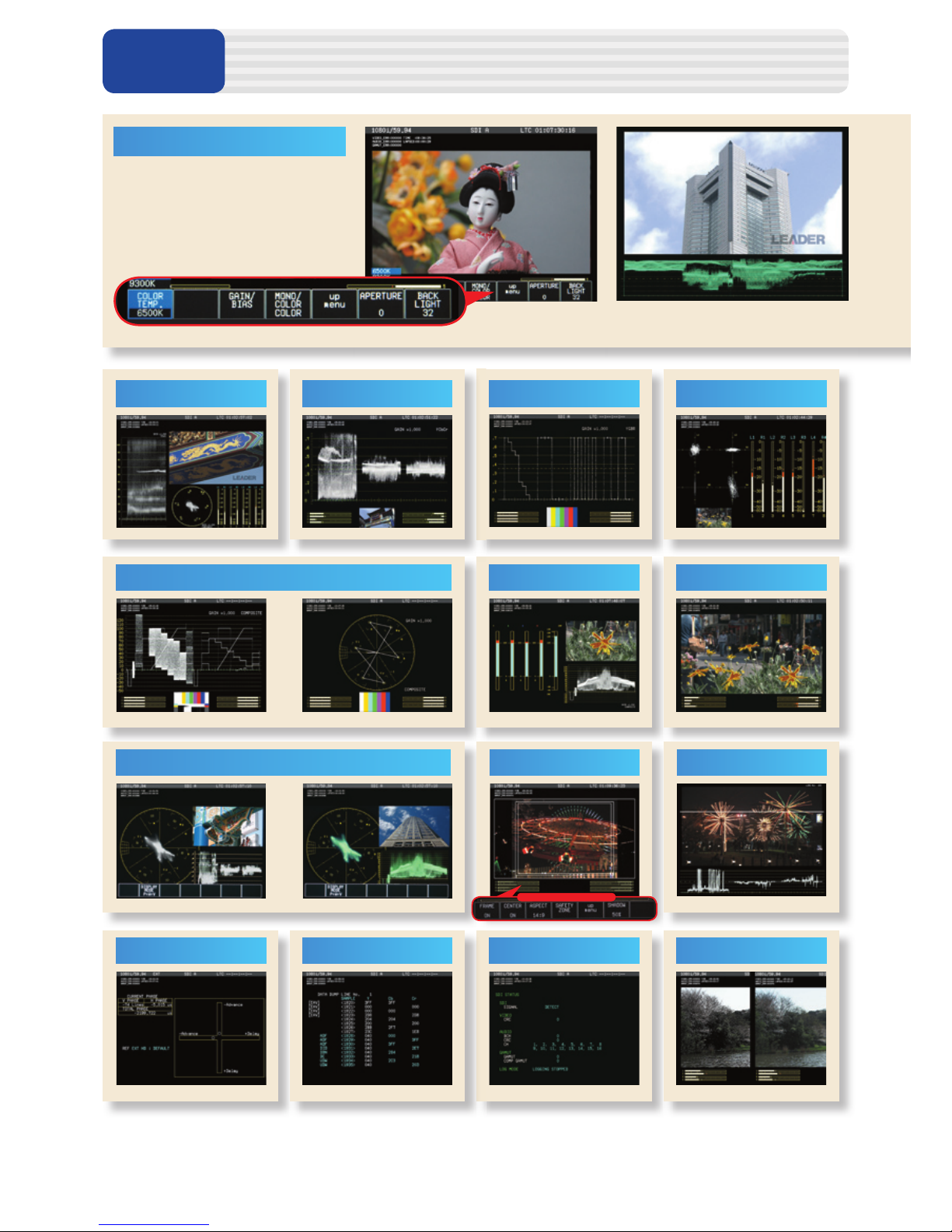
Waveform Display
Waveform Operation
Display Mode
Overlay Display: Overlays component signals
Parade Display: Displays component signals side by side
Blanking Period: H and V blanking periods can be masked
RGB Conversion: Converts Y, CB, CRsignals into RGB and displays
the result
Pseudo-Composite Display
:Digitally converts component signals into com-
posite signals and displays the result
Channel Assignments: The G, B, R order or R, G, B order selectable for
RGB conversion display
Line Select: Displays the selected line
Vertical Axis
Gain: ×1 or ×5 selectable
Variable Gain: ×0.2 to ×2.0
Amplitude Accuracy: ≤ ±0.5 %
Frequency Characteristics HDTV
Y Signal: ≤ ±0.5 % for 1 to 30 MHz
C
B, CRSignals: ≤ ±0.5 % for 0.5 to 15 MHz
Low-Pass Attenuation: ≥ 20 dB (at 20 MHz)
Frequency Characteristics SDTV
Y Signal: ≤ ±0.5 % for 1 to 5.75 MHz
C
B, CRSignals: ≤ ±0.5 % for 0.5 to 2.75 MHz
Low-Pass Attenuation: ≥ 20 dB (at 3.8 MHz)
Horizontal Axis
Line Display: ×1, ×10, ×20, ACTIVE, or BLANK selectable
Field Display: ×1, ×20, or ×40 selectable
Cursor Measurement
Types: Two horizontal cursors (REF and DELTA)
Two vertical cursors (REF and DELTA)
Amplitude Measurement: Measures in % or V
Time Measurement: Measures in usec or msec
Frequency Display: Displays the frequency by assuming the interval
between the cursors to be one period
Scale
Type: % scale or V scale selectable
Color: Selectable from seven colors
Thumbnail Display: Can display thumbnails of picture displays and
audio level meters
Vectorscope Display
Gain: ×1, ×5, or IQ-MAG selectable
Variable Gain: ×0.2 to ×2.0
Amplitude Accuracy: ≤ ±0.5 %
Scale
Type: 75 % or 100 % selectable
IQ Axis: Show or hide selectable
Color: Selectable from seven colors
Pseudo-Composite Display: Digitally converts component signals into compos-
ite signals and displays the result
Thumbnail Display: Can display thumbnails of picture displays and au-
dio level meters
5 Bar Display
Bar Display:
Displays the peak levels of Y, R, G, B, and composite
Channel Assignments: RGB or GBR selectable
Scale: mV or % selectable
Error Level: Based on gamut error level and composite gamut
error level settings, user settable.
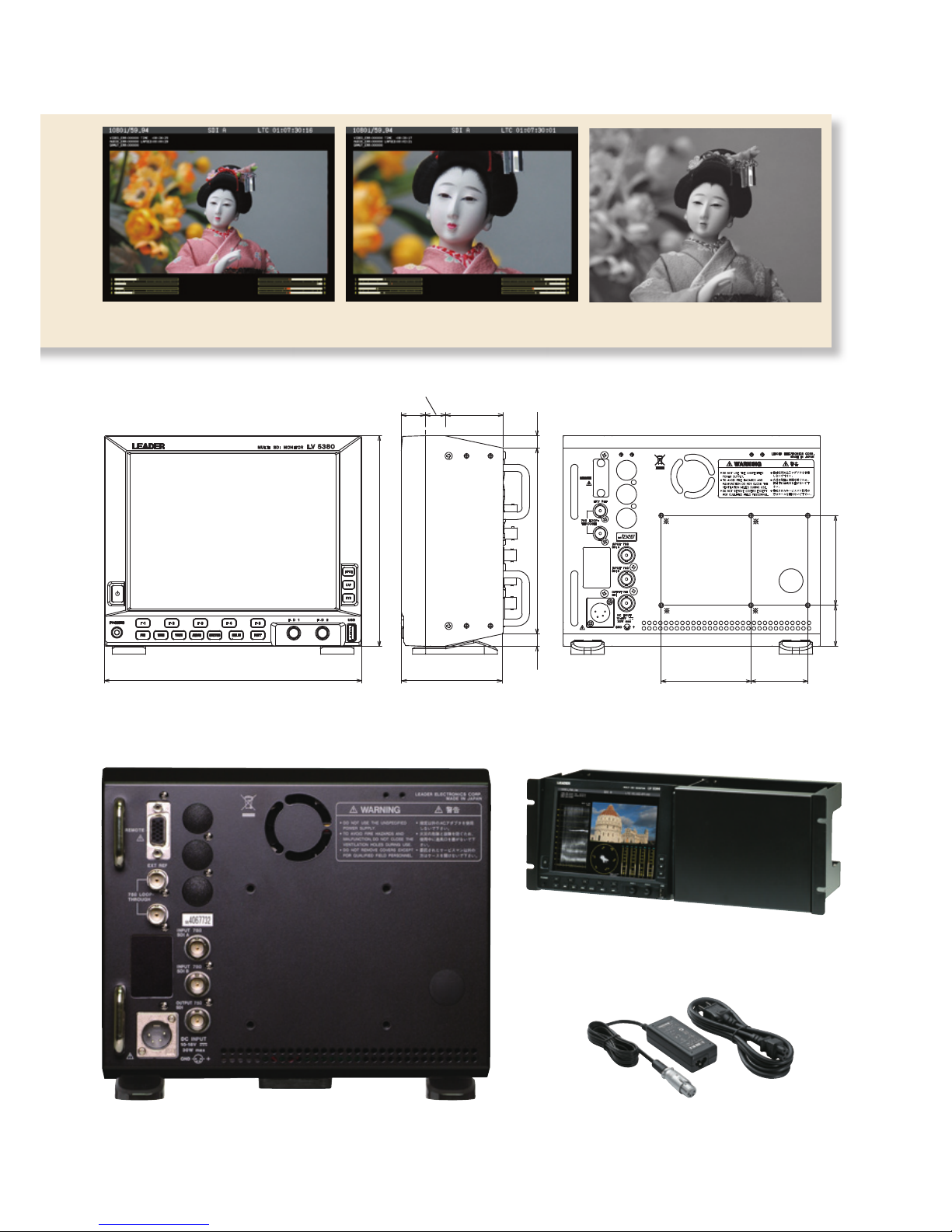
Picture Display
Color Temperature: 6500K or 9300K selectable
Quality Adjustment: Brightness, contrast, gain, bias, aperture
Display Size: Fit, full frame, real, and 4:3 full screen
Color: R, G, or B can be turned off separately. Variable
chroma gain and monochrome available.
Frame Rate: Displays by converting the frame rate using the
internal sync signal
Aspect Marker Display: 4:3, 13:9, 14:9, or 16:9 selectable
Aspect Marker Format: Line, shadow (three types), black
Safety Marker Size: ARIB TR-B4, SMPTE RP-218, or user-dened se-
lectable
Line Select: Displays a mark on the selected line
Gamut Error Display: Displays gamut error locations over the picture
Thumbnail Display: Displays thumbnails of audio level meters
Embedded Audio Display
Lissajous Display
Display Channels: 2ch (single) or 8ch (multi) selectable
Display Mode: X-Y or L-R selectable
Level Meter Display
Display Channels: 2ch or 8ch display selectable
Meter: 60 dB peak level, 90 dB peak level, or average
selectable. (Peak level meters include setable peak
hold indication.)
Channels
Group Selection: Select any two groups within the same SDI channel
from groups 1, 2, 3, and 4
Audio Information Detection
:Detects the presence of each audio channel
Sampling Frequency:
48 kHz (must be synchronized with the video signal)
Status Display
Event Log: Stores up to 1,000 events
Data Dump Display: Dumps data by serial data sequence or by channel
Data Output:
Can be saved in text format to USB memory or to a PC
Phase Difference Display
Display: Displays numerically and graphically the phase
difference between an SDI signal and the external
sync signal
Display Range
Vertical: ±1 eld (for interlace)
±1/2 frame (for progressive)
Horizontal: ±1 line
Error Count
Error Count: Counts up to 999,999 video, audio, and gamut er-
rors separately
Count Period: Counts all errors that occur in one eld as one error
Video Errors
CRC Error: Detects transmission errors of HD-SDI signals
EDH Error: Detects transmission errors of SD-SDI signals
Gamut Error
Gamut Error: Detects gamut errors
Detection Range Upper Limit
:90.0 to 109.4 %
Lower Limit
:-7.2 to +6.1 % (0.1 % steps)
Composite Gamut Error: Monitors level errors when component signals are
converted to composite signals
Detection Range Upper Limit
:90.0 to 135.0 %
Lower Limit
:-40 to -20 % (0.1 % steps)
Audio Errors
CRC Error: Detects CRC errors in channel status bits
BCH Errors:
Detects transmission errors of HD-SDI audio packets
Time Display
Current Time Display: Time display based on the internal clock
Elapsed Time: Time elapsed since the error count was cleared
Time Code: LTC or VITC selectable (complies with SMPTE
RP-188)
Other Display Features
ID Display: ID can be assigned to each input channel.
Tally Indicator: One of the remote connectors can be modied so
that tally indication can be shown on the screen (to
be supported in the future).
Front Panel
Key LEDs: All keys illuminate dimly. (The selected key illumi-
nates brightly.)
Last Memory: Backs up panel settings to memory
Environmental Conditions
Operating Temperature: 0 to 40 °C
Operating Humidity Range: ≤ 85 % RH (without condensation)
Operating Environment: Indoors
Overvoltage Category: I
Pollution Degree: 2
Power Requirements
10 to 18 VDC, 30 W max.
Dimensions
215 (W) × 176 (H) × 85 (D) mm (excluding projections)
Weight
2.0 kg
Accessory
Instruction manual ............................................... 1
Ferrite core .......................................................... 1
Option Sold Separately
AC adapter LP 1960
Rack mount LP 2751 I
Blank Panel LC 2129
*1
(
・
The video signal waveform display and vectorscope display may be
delayed by up to 1 frame with respect to the picture display.
・
V sweep cannot be displayed when the video signal waveform displays
for two simultaneous inputs are shown.
・
Phase difference accurary between external reference and internal
signal is ±1 clock cycle.
)