1. SPECIFICATIONS
1. SPECIFICATIONS
1.1 General
5
s
Y
1.2
O
the color system of the input video signal.
1.3 Specifications
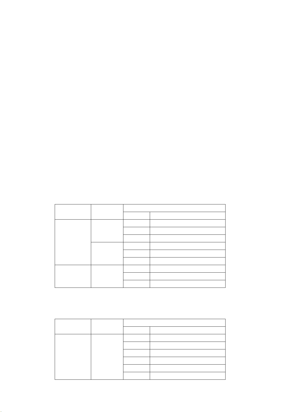
.3.1 Supported Formats
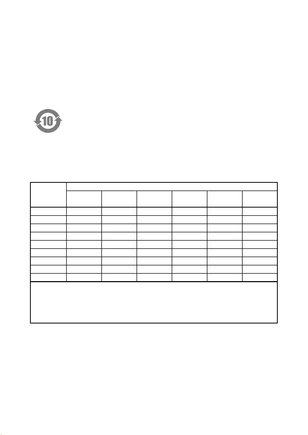
Table 1-1 Dual link system video
Format
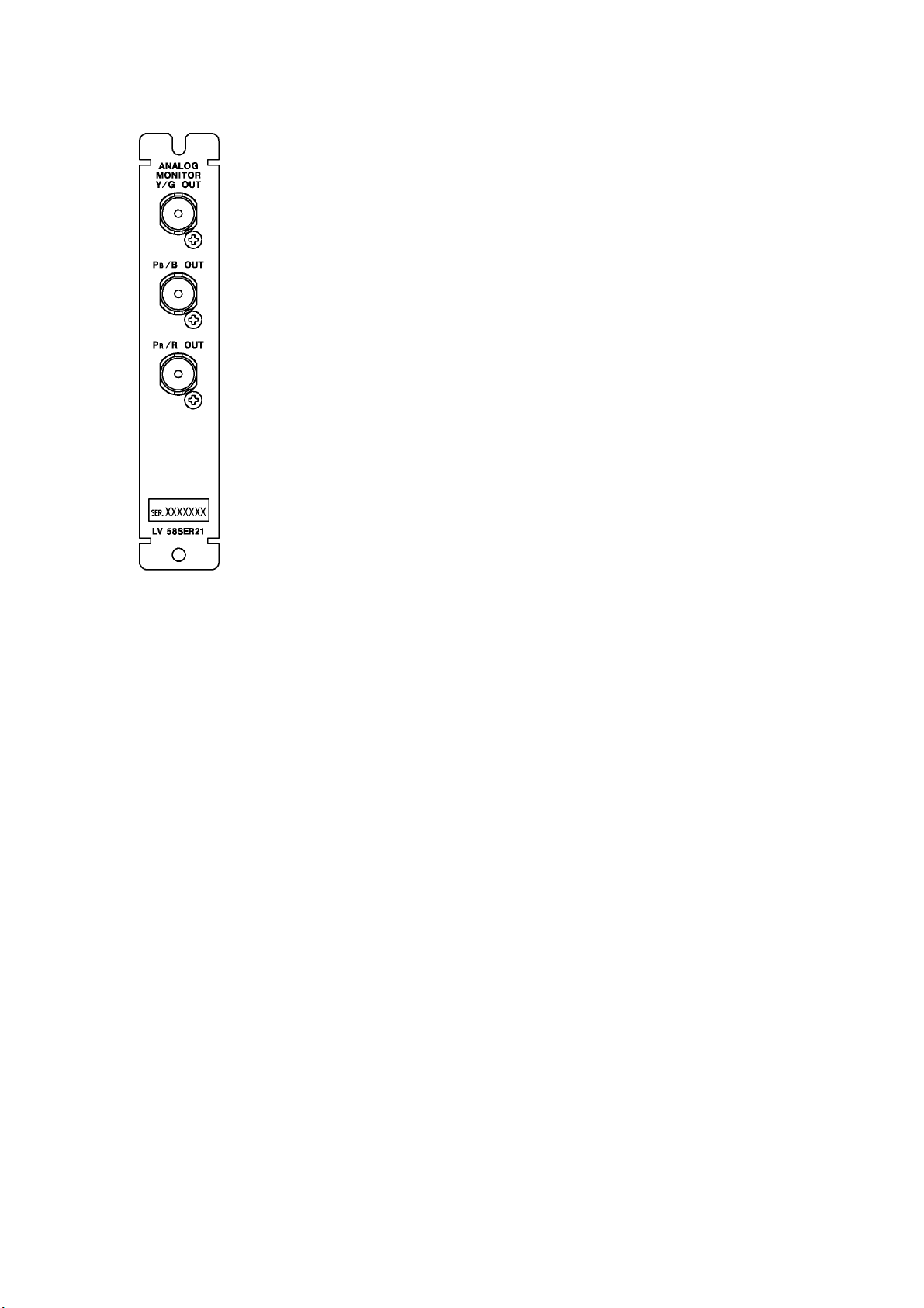
The LV 58SER21 converts one of the video signals received by the LV 58SER01A or LV
8SER04 unit in the LV 5800 or LV 7800 into an analog component signal and transmits the
ignal.
ou can use the LV 58SER21 to display a video signal on an analog picture monitor.
Features
Analog Component Signal Output
You can display one of the video signals being measured by the LV on an analog picture
monitor. You can transmit the signal using one of two output modes. In one mode, the
signal in the selected area of the LV display is transmitted. In the other mode, the
transmitted signal is fixed.
utput Signal Format Conversion
You can switch the output video signal format between YPBPRand GBR, regardless of
1
Color System Quantization Scanning Frame (Field) Rates
GBR 4:4:4 10 bit 1080p 30/29.97/25/24/23.98
1080PsF 30/29.97/25/24/23.98
1080i 60/59.94/50
12 bit 1080p 30/29.97/25/24/23.98
1080PsF 30/29.97/25/24/23.98
1080i 60/59.94/50
YPBPR4:2:2 12 bit 1080p 30/29.97/25/24/23.98
1080PsF 30/29.97/25/24/23.98
1080i 60/59.94/50
* Phase differences of up to 100 clocks (approx. 1.4 μs) between links A and B are automatically
corrected.
Table 1-2 Single link system video
Format
Color System Quantization Scanning Frame (Field) Rates
YPBPR4:2:2 10 bit 1080i 60/59.94/50
1080p 30/29.97/25/24/23.98
1080PsF 30/29.97/25/24/23.98
720p 60/59.94/50/30/29.97/25/24/23.98
525 59.94
625 50
1