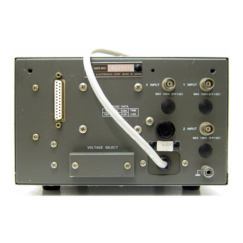
Leader LV 5380 OP72 User manual

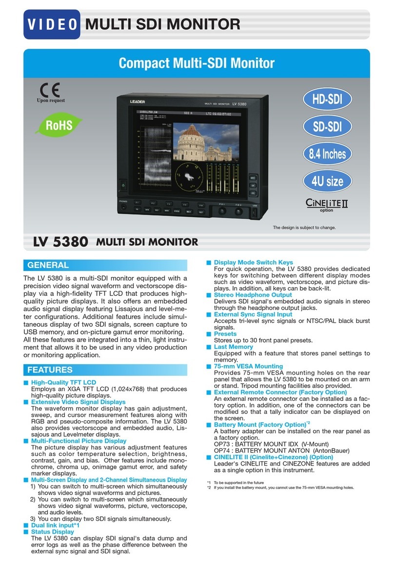
LV 5380 MULTI SDI MONITOR
LV 5380 OP72 REMOTE & TALLY
LV 5380 OP73 BATTERY MOUNT IDX
LV 5380 OP74 BATTERY MOUNT ANTON
INSTRUCTION MANUAL

Contents
GENERAL SAFETY SUMMARY ......................................................................................... I
1. INTRODUCTION ........................................................................................................ 1
1.1 Scope of Warranty .................................................................................................................. 1
1.2 Handling Precautions.............................................................................................................. 1
1.2.1 Power Supply Voltage...................................................................................................... 1
1.2.2 Maximum Allowable Input Voltage ................................................................................... 2
1.2.3 Shorting and Applying External Input to the Output Connectors...................................... 2
1.2.4 Backup Battery ................................................................................................................ 2
1.2.5 Mechanical Shock............................................................................................................ 2
1.2.6 Electrostatic Damage....................................................................................................... 2
1.2.7 Warming Up..................................................................................................................... 2
2. SPECIFICATIONS ...................................................................................................... 3
2.1 General ................................................................................................................................... 3
2.2 Features.................................................................................................................................. 3
2.3 Specifications.......................................................................................................................... 6
2.3.1 Video Signal Formats and Corresponding Standards ...................................................... 6
2.3.2 Audio Playback................................................................................................................ 7
2.3.3 Input/Output Connectors.................................................................................................. 7
2.3.4 Control Connector............................................................................................................ 8
2.3.5 LCD ................................................................................................................................. 8
2.3.6 Screen Capture................................................................................................................ 8
2.3.7 Presets ............................................................................................................................ 8
2.3.8 Video Signal Waveform Display....................................................................................... 9
2.3.9 Vector Display................................................................................................................ 10
2.3.10 5 Bar Display ................................................................................................................. 10
2.3.11 Picture Displays ............................................................................................................. 10
2.3.12 Embedded Audio Display............................................................................................... 11
2.3.13 Status Display................................................................................................................ 11
2.3.14 Error Counting ............................................................................................................... 12
2.3.15 Time Display .................................................................................................................. 13
2.3.16 3D Assist Display ........................................................................................................... 13
2.3.17 Histogram Display.......................................................................................................... 15
2.3.18 Other DisplayFeatures.................................................................................................. 15
2.3.19 Front Panel .................................................................................................................... 15
2.3.20 General Specifications ................................................................................................... 15
2.4 LV 5380 OP72 (REMOTE & TALLY) ..................................................................................... 16
2.4.1 General.......................................................................................................................... 16
2.4.2 Features ........................................................................................................................16
2.4.3 Specifications................................................................................................................. 16
2.5 LV 5380 OP73 (BATTERY MOUNT IDX) .............................................................................. 18
2.5.1 General.......................................................................................................................... 18
2.5.2 Features ........................................................................................................................18
2.5.3 Specifications................................................................................................................. 18

2.6 LV 5380 OP74 (BATTERY MOUNT ANTON)........................................................................ 19
2.6.1 General.......................................................................................................................... 19
2.6.2 Features ........................................................................................................................19
2.6.3 Specifications................................................................................................................. 19
3. COMPONENT NAMES AND FUNCTIONS .............................................................. 20
3.1 Front Panel ........................................................................................................................... 20
3.2 Rear Panel............................................................................................................................ 22
3.3 Bottom Panel ........................................................................................................................ 23
4. BEFORE YOU BEGIN MEASURING ....................................................................... 24
4.1 Preparing the Power Supply ................................................................................................. 24
4.1.1 Attaching the Ferrite Core.............................................................................................. 24
4.1.2 Attaching the DC Power Cord........................................................................................ 25
4.1.3 Turning on the Power..................................................................................................... 25
4.1.4 Turning off the Power..................................................................................................... 25
4.1.5 Using a Battery (Option) ................................................................................................ 26
4.2 Applying SDI Input Signals ................................................................................................... 26
4.3 Switching between SDI Signals (INPUT) .............................................................................. 27
4.4 Transmitting an SDI Output Signal........................................................................................ 27
4.5 Applying an External Sync Signal ......................................................................................... 28
4.6 Using a VESAStand ............................................................................................................. 29
4.7 Enabling the Key Lock .......................................................................................................... 30
4.8 General Display Explanation................................................................................................. 30
4.9 Basic Panel Operations ........................................................................................................ 32
4.10 Displaying Menus ................................................................................................................. 33
5. SYSTEM SETTINGS (SYS) ..................................................................................... 35
5.1 Setting the Input Format ....................................................................................................... 35
5.1.1 Selecting a Link Format ................................................................................................. 35
5.1.2 Setting the Input Format Detection Method ................................................................... 36
5.1.3 Selecting i or PsF........................................................................................................... 36
5.1.4 Setting the Input Format ................................................................................................ 37
5.1.5 Setting the Composite Display Format .......................................................................... 38
5.2 LCD Settings......................................................................................................................... 38
5.2.1 Setting the Auto Shutoff Time ........................................................................................ 38
5.2.2 Adjusting the Backlight .................................................................................................. 39
5.3 Setting the Channel ID..........................................................................................................39
5.3.1 Creating an ID................................................................................................................ 40
5.4 Configuring the Display.........................................................................................................41
5.4.1 Selecting the Timecode Display Format ........................................................................ 41
5.4.2 Displaying the Error Counter and Time.......................................................................... 41
5.4.3 Displaying the Input Format........................................................................................... 42
5.4.4 Selecting the Input SDI Signal Display Format .............................................................. 42
5.5 Remote Settings (Option) ..................................................................................................... 42
5.5.1 Selecting the Method for Loading Presets ..................................................................... 43
5.5.2 Setting the Alarm Signal Polarity.................................................................................... 43
5.5.3 Setting the Channels Whose Errors Are Indicated by the Alarm Signal ......................... 43

5.6 Setting the Date and Time .................................................................................................... 44
5.6.1 Setting the Date............................................................................................................. 44
5.6.2 Setting the Time............................................................................................................. 44
5.7 Initialization ........................................................................................................................... 45
5.7.1 Initializing the Settings ................................................................................................... 45
5.8 Setting the Menu Display Time ............................................................................................. 45
5.9 Remaining Battery Power Display (Option)........................................................................... 45
5.10 License Settings ................................................................................................................... 46
5.10.1 Installing Options ........................................................................................................... 46
5.10.2 Viewing the MAC Address and Installed Options........................................................... 47
6. MULTI-SCREEN DISPLAY FEATURE (MULTI)........................................................ 48
6.1 Switching between the Single-Screen and Multi-Screen Displays ........................................ 48
6.2 Selecting the Display Mode .................................................................................................. 49
6.3 Selecting the Multi-Screen Display Format ........................................................................... 50
6.4 Configuring Wipe Display Settings........................................................................................ 53
6.5 Setting Each Measurement Mode......................................................................................... 53
6.6 Switching between the Video Signal Waveform and Histogram Sub Items........................... 54
6.7 Configuring Video Signal Waveform Settings ....................................................................... 54
6.7.1 Selecting the Display Format......................................................................................... 55
6.7.2 Selecting the Video Signal Waveform Color .................................................................. 55
6.8 Setting the Histogram ...........................................................................................................56
6.8.1 Selecting the Display Format......................................................................................... 56
6.8.2 Selecting the Channels To Display ................................................................................ 57
6.8.3 Turning Y, R, G, and B On and Off ................................................................................. 57
6.9 User-Defined Layout Settings ............................................................................................... 57
6.9.1 Displaying User Layouts ................................................................................................ 58
6.9.2 Copying All Layout Files ................................................................................................ 58
7. 3D ASSIST DISPLAY FEATURE .............................................................................. 59
7.1 Selecting the Input Signal ..................................................................................................... 59
7.2 Selecting the Display Format ................................................................................................ 60
7.3 Configuring Checkerboard DisplaySettings ......................................................................... 62
7.4 Configuring Wipe Display Settings........................................................................................ 62
7.4.1 Turning the Boundary Lines On and Off ........................................................................ 62
7.4.2 Moving Boundary Lines ................................................................................................. 63
7.5 Setting the Inverted Display .................................................................................................. 63
7.6 Selecting the Measurement Mode ........................................................................................ 64
7.7 Configuring Grid Display Settings ......................................................................................... 64
7.7.1 Selecting the Displayed Grid ......................................................................................... 65
7.7.2 Selecting the Grid to Configure...................................................................................... 65
7.7.3 Adjusting the Grid Line Spacing..................................................................................... 66
7.7.4 Selecting the Grid Line Adjustment Unit ........................................................................ 66
7.7.5 Adjusting the Grid Line Positions................................................................................... 66
7.7.6 Selecting the Grid Line Color......................................................................................... 67
7.8 Configuring Disparity Measurement Settings........................................................................ 67
7.8.1 Disparity Measurement Display Explanation ................................................................. 67
7.8.2 Disparity Measurement Procedure ................................................................................ 69

8. PRESET FEATURE (PSET) ..................................................................................... 72
8.1 Presets.................................................................................................................................. 73
8.1.1 Registering Presets ....................................................................................................... 73
8.1.2 Loading Presets............................................................................................................. 74
8.1.3 Deleting Presets ............................................................................................................ 74
8.2 Display Mode Presets ........................................................................................................... 75
8.2.1 Registering DisplayMode Presets................................................................................. 75
8.2.2 Loading Display Mode Presets ...................................................................................... 76
8.2.3 Deleting Display Mode Presets...................................................................................... 77
8.3 Copying Presets.................................................................................................................... 78
8.3.1 Copying Presets from USB Memory to the LV 5380 ...................................................... 78
8.3.2 Copying Presets from the LV 5380 to USB Memory ...................................................... 78
9. SCREEN CAPTURE FEATURE (CAP) .................................................................... 79
9.1 Taking a Screen Capture of the Display................................................................................ 80
9.2 Saving Screen Capture Data to USB Memory ...................................................................... 81
9.3 Displaying Screen Capture Data on the LV 5380.................................................................. 82
9.4 Viewing USB Memory Screen Capture Data......................................................................... 83
10. PICTURE DISPLAY (PIC)......................................................................................... 84
10.1 General Picture Display Explanation .................................................................................... 84
10.2 Setting the Brightness and Contrast ..................................................................................... 86
10.2.1 Setting the Brightness.................................................................................................... 86
10.2.2 Setting the Contrast ....................................................................................................... 86
10.3 Adjusting the Picture (ADJUST)............................................................................................ 87
10.3.1 Switching between the Color and Monochrome Displays .............................................. 87
10.3.2 Increasing the Chroma Gain.......................................................................................... 87
10.3.3 Turning RGB On and Off ............................................................................................... 88
10.3.4 Setting the RGB Gain .................................................................................................... 88
10.3.5 Setting the RGB Bias..................................................................................................... 88
10.3.6 Setting the Chroma Gain ............................................................................................... 89
10.3.7 Setting the Monitor’s Color Temperature ....................................................................... 89
10.3.8 Setting the Aperture ....................................................................................................... 89
10.3.9 Adjusting the Backlight .................................................................................................. 90
10.4 Setting Markers (MARKER) .................................................................................................. 90
10.4.1 Displaying a Frame Marker............................................................................................ 91
10.4.2 Displaying a Center Marker ........................................................................................... 91
10.4.3 Displaying an Aspect Marker ......................................................................................... 92
10.4.4 Selecting the Aspect Marker Type ................................................................................. 92
10.4.5 Selecting the Safety Marker Type .................................................................................. 93
10.4.6 Displaying a Safe Action Marker .................................................................................... 94
10.4.7 Displaying a Safe Title Marker ....................................................................................... 94
10.4.8 Displaying User Markers................................................................................................ 94
10.4.9 Setting User Marker Sizes ............................................................................................. 95
10.5 Line Selection Settings (LINE SEL) ...................................................................................... 96
10.5.1 Displaying a Marker on the Selected Line ..................................................................... 96
10.5.2 Selecting a Line ............................................................................................................. 97
10.5.3 Setting the Line Selection Range .................................................................................. 97

10.6 Display Settings (DISPLAY).................................................................................................. 97
10.6.1 Setting the Display Size................................................................................................. 98
10.6.2 Setting the Display Position ........................................................................................... 99
10.6.3 Displaying Gamut Errors.............................................................................................. 100
10.6.4 Displaying the Audio Meter .......................................................................................... 101
10.6.5 Selecting the Audio Meter Display Format................................................................... 101
10.6.6 Selecting the SD Signal Display Format ...................................................................... 102
10.7 CINELITE Settings (for the CINELITE option) .................................................................... 102
11. VIDEO SIGNAL WAVEFORM DISPLAY (WFM) ..................................................... 103
11.1 General Video Signal Waveform Display Explanation......................................................... 103
11.2 Display Position Settings .................................................................................................... 105
11.2.1 Setting the Horizontal Position..................................................................................... 105
11.2.2 Setting the Vertical Position ......................................................................................... 105
11.3 Video Signal Waveform and Scale Settings (INTEN/SCALE) ............................................. 106
11.3.1 Setting the Scale Units ................................................................................................ 106
11.3.2 Changing the Scale Color............................................................................................ 107
11.3.3 Changing the Video Signal Waveform Color................................................................ 108
11.3.4 Setting the Contrast ..................................................................................................... 108
11.3.5 Displaying Markers for 75 % Intensity Color Bars........................................................ 108
11.3.6 Displaying Horizontal Markers ..................................................................................... 109
11.3.7 Setting the Video Signal Waveform Intensity ............................................................... 110
11.3.8 Setting the Scale Intensity ........................................................................................... 110
11.4 Gain and Sweep Settings (GAIN/SWEEP) ..........................................................................111
11.4.1 Switching between the Overlay and Parade Displays...................................................111
11.4.2 Selecting the Sweep Method ....................................................................................... 112
11.4.3 Setting the Horizontal Magnification ............................................................................ 115
11.4.4 Setting the Fixed Vertical Gain .................................................................................... 116
11.4.5 Setting the Variable Vertical Gain ................................................................................ 116
11.5 Line Selection and Sync Signal Settings (LINE SEL EXT REF).......................................... 117
11.5.1 Displaying the Waveform of the Selected Line ............................................................ 117
11.5.2 Selecting a Line ........................................................................................................... 118
11.5.3 Setting the Line Selection Range ................................................................................ 118
11.5.4 Switching to an External Sync Signal .......................................................................... 118
11.6 Display Settings (DISPLAY)................................................................................................ 119
11.6.1 Selecting the Display Format....................................................................................... 120
11.6.2 Displaying the GBR or RGB Signal Simultaneously with the Luminance Signal.......... 121
11.6.3 Setting the Setup Level................................................................................................ 122
11.6.4 Turning YCBCR, GBR, or RGB Signal Components On and Off................................... 122
11.6.5 Selecting a Filter .......................................................................................................... 123
11.6.6 Displaying the Blanking Period .................................................................................... 124
11.6.7 Displaying the Audio Meter .......................................................................................... 125
11.6.8 Selecting the Audio Meter Display Format................................................................... 125
11.6.9 Displaying the Picture .................................................................................................. 126
11.7 Cursor Settings ................................................................................................................... 127
11.7.1 Displaying Cursors....................................................................................................... 127
11.7.2 Selecting the Cursor Type ........................................................................................... 128
11.7.3 Moving the Cursors...................................................................................................... 128
11.7.4 Setting the Units of Measurement................................................................................ 129
11.7.5 Setting the Base Value ................................................................................................ 129
12. VECTOR DISPLAY (VECT) .................................................................................... 130
12.1 General Vector Display Explanation ................................................................................... 130
12.2 Vector and Scale Settings (INTEN/SCALE) ........................................................................ 132
12.2.1 Displaying the I and Q Axes......................................................................................... 132
12.2.2 Changing the Scale Color............................................................................................ 133
12.2.3 Changing the Vector Color........................................................................................... 133
12.2.4 Setting the Contrast ..................................................................................................... 133
12.2.5 Setting the Vector Intensity .......................................................................................... 134
12.2.6 Setting the Scale Intensity ........................................................................................... 134
12.3 Gain Settings (GAIN) .......................................................................................................... 134
12.3.1 Setting the Fixed Gain ................................................................................................. 134
12.3.2 Setting the Variable Gain ............................................................................................. 135
12.4 Line Selection and Sync Signal Settings (LINE SEL EXT REF).......................................... 136
12.4.1 Displaying the Vector of the Selected Line .................................................................. 136
12.4.2 Selecting a Line ........................................................................................................... 137
12.4.3 Setting the Line Selection Range ................................................................................ 137
12.4.4 Switching to an External Sync Signal .......................................................................... 137
12.5 Display Settings (DISPLAY)................................................................................................ 138
12.5.1 Switching between the Vector and 5 Bar Displays....................................................... 138
12.5.2 Displaying the Audio Meter .......................................................................................... 139
12.5.3 Selecting the Audio Meter Display Format................................................................... 139
12.5.4 Displaying the Picture .................................................................................................. 140
12.6 Display Format Settings (COLOR SYSTEM) ...................................................................... 141
12.6.1 Selecting the Display Format....................................................................................... 141
12.6.2 Setting the Setup Level................................................................................................ 142
12.6.3 Displaying a Scale for 75 % Color Bars ....................................................................... 142
12.7 5 Bar Settings (5BAR SETUP)............................................................................................ 143
12.7.1 General 5 Bar Display Explanation .............................................................................. 143
12.7.2 Changing the Signal Display Order.............................................................................. 144
12.7.3 Setting the Scale Units ................................................................................................ 145
13. AUDIO DISPLAY (AUDIO)...................................................................................... 146
13.1 General Audio Display Explanation..................................................................................... 146
13.2 Input Channel Settings (CHANNEL SELECT) .................................................................... 148
13.2.1 Selecting the Audio Display Input Channels ................................................................ 149
13.2.2 Selecting Input Channels in the Single Lissajous Display............................................ 150
13.2.3 Selecting the Headphone Jack Output Channels ........................................................ 150
13.3 Meter Settings (METER SETUP)........................................................................................ 151
13.3.1 Setting the Reference Level ........................................................................................ 151
13.3.2 Setting the Range ........................................................................................................ 152
13.3.3 Selecting the Scale...................................................................................................... 152
13.3.4 Setting the Peak Value Hold Time ............................................................................... 152
13.3.5 Meter Settings Overview.............................................................................................. 153
13.4 Lissajous Settings (LISSAJOU SETUP) ............................................................................. 154
13.4.1 Selecting the Display Format....................................................................................... 154

13.4.2 Selecting the Scale Display Format ............................................................................. 155
13.4.3 Setting the Gain........................................................................................................... 156
13.4.4 Setting the Lissajous Curve Intensity........................................................................... 156
13.4.5 Setting the Scale Intensity ........................................................................................... 156
13.5 Display Settings (DISPLAY)................................................................................................ 157
13.5.1 Displaying the Picture .................................................................................................. 157
13.6 Headphone Settings (VOLUME)......................................................................................... 158
13.6.1 Adjusting the Headphone Volume................................................................................ 158
14. STATUS DISPLAY (STATUS) ................................................................................. 159
14.1 General Status Display Explanation.................................................................................... 159
14.2 Event Log Settings (EVENT LOG) ...................................................................................... 164
14.2.1 General Event Log Explanation ................................................................................... 164
14.2.2 Scrolling through the Event Log................................................................................... 166
14.2.3 Starting Event Logging................................................................................................. 166
14.2.4 Deleting the Event Log ................................................................................................ 166
14.2.5 Setting the Event Log Overwrite Mode ........................................................................ 166
14.2.6 Saving the Event Log to USB Memory ........................................................................ 167
14.3 Data Dump Settings (DATA DUMP) .................................................................................... 167
14.3.1 General Data Dump Explanation ................................................................................. 168
14.3.2 Selecting a Line in the Data Dump Display.................................................................. 169
14.3.3 Scrolling through the Data Dump Display Samples ..................................................... 169
14.3.4 Setting the Data Dump Display Mode.......................................................................... 170
14.3.5 Selecting the Data Dump Display Format .................................................................... 170
14.3.6 Setting the Data Dump Display Start Location............................................................. 172
14.3.7 Saving a Data Dump to USB Memory ......................................................................... 172
14.4 Phase Difference Measurement Settings (EXT REF PHASE) ............................................ 174
14.4.1 Phase Difference Measurement Display Explanation .................................................. 175
14.4.2 Configuring a User-Defined Phase Difference Setting................................................. 177
14.4.3 Using the Default Phase Difference Setting................................................................. 177
14.4.4 Displaying the Phase Difference between Channels A and B...................................... 178
14.4.5 Displaying the Phase Difference between Links A and B............................................. 178
14.4.6 Switching to an External Sync Signal .......................................................................... 178
14.5 Error Settings (ERROR CONFIG)....................................................................................... 179
14.5.1 Detecting CRC Errors .................................................................................................. 180
14.5.2 Detecting EDH Errors .................................................................................................. 180
14.5.3 Detecting BCH Errors .................................................................................................. 180
14.5.4 Detecting CRC Errors .................................................................................................. 181
14.5.5 Turning the Low Pass Filter ON and OFF.................................................................... 181
14.5.6 Selecting the Filter Characteristics .............................................................................. 181
14.5.7 Detecting Gamut Errors ............................................................................................... 182
14.5.8 Configuring Gamut Error Detection Settings................................................................ 182
14.5.9 Detecting Composite Gamut Errors ............................................................................. 183
14.5.10 Configuring Composite Gamut Error Detection Settings.............................................. 183
14.5.11 Detecting Luminance Errors ........................................................................................ 184
14.5.12 Configuring Luminance Error Detection Settings ......................................................... 184
14.6 Clearing Errors (ERROR CLEAR) ...................................................................................... 185
14.6.1 Clearing Errors............................................................................................................. 185

15. External Interface (Option)...................................................................................... 186
15.1 Remote Control Feature ..................................................................................................... 186
15.1.1 Remote Control Connector Specifications ................................................................... 186
15.1.2 Control.........................................................................................................................187
15.1.3 Loading Presets........................................................................................................... 188
15.1.4 Switching the Input Channel ........................................................................................ 189
15.1.5 Displaying a Tally Indication......................................................................................... 189
15.1.6 Transmitting the Alarm Signal ...................................................................................... 190
16. APPENDIX ............................................................................................................. 191
16.1 Menu Tree........................................................................................................................... 191
16.1.1 Picture Menu ............................................................................................................... 191
16.1.2 Video Signal Waveform Menu ..................................................................................... 194
16.1.3 Vector Menu ................................................................................................................ 198
16.1.4 Audio Menu ................................................................................................................. 199
16.1.5 Status Menu................................................................................................................. 201
16.1.6 Multi-Screen Display Menu.......................................................................................... 203
16.1.7 Screen Capture Menu.................................................................................................. 206
16.1.8 Preset Registration Menu ............................................................................................ 207
16.1.9 System Menu............................................................................................................... 208
16.2 Firmware Revision History .................................................................................................. 211
INDEX

I
GENERAL SAFETY SUMMARY
■Read This before Using the Instrument
This instrument should only be used by persons with sufficient knowledge of electronics who
thoroughly understand the contents of this manual.
This instrument is not designed or manufactured for households or ordinary consumers.
If a person without sufficient knowledge of electronics uses this instrument, it may be damaged,
and the user may be injured. Such a person should not use this instrument unless they are
supervised by a person who does posses such knowledge.
■Note about Reading This Manual
The contents of this manual contain specialized terminology and may be difficult to understand. If
you have any questions about the contents of this manual, please contact your local LEADER
agent.
■Symbols and Terms
The following symbols and terms are used in this instruction manual and on the instrument to
indicate important warnings and notes.
<Symbol>
This symbol appears in this instruction manual and on the instrument to
indicate an area where improper handling could result in personal injury,
damage to the instrument, or malfunction of the instrument or devices
connected to it.
When you encounter this symbol on the instrument, be sure to refer to the
information in this instruction manual that corresponds to the area that the
symbol marks.
<Term>
Ignoring the precautions that this term indicates could lead to death or
serious injury.
<Term>
Ignoring the precautions that this term indicates could lead to personal
injury or damage to the instrument.

II
GENERAL SAFETY SUMMARY
Read the warnings and information below thoroughly to avoid death, personal injury, and damage and
deterioration of the instrument.
■Warnings Concerning the Case and Panels
Do not remove the instrument's case or panels for any reason. Touching the internal
components of the instrument could lead to fire or electric shock.
Also, do not allow foreign materials, such as liquids, combustible matter, and metal, to enter the
instrument. Turning the instrument on when such materials are inside it could lead to fire,
electric shock, damage to the instrument, or some other accident.
■Warning Concerning the Power Source
Do not use a power source with a voltage other than the rated power source voltage for the
instrument. Doing so could lead to fire.
■Installation Environment
●Operating Temperature Range
Use this instrument in a 0 to 40 C environment. Using the instrument with its vents blocked
or in a high temperature environment could lead to fire.
Drastic changes in temperature, such as might be caused by moving the instrument between
two rooms with different temperatures, can damage the instrument by causing condensation
to form within it. If there is a possibility that the instrument has condensation within it, wait for
approximately 30 minutes before turning on the power.
●Operating Humidity Range
Use this instrument in an environment whose relative humidity is 85 % or less where there is
no threat of condensation forming.
Also, do not operate this instrument with wet hands. Doing so could lead to electric shock or
fire.
●Do Not Operate in an Explosive Atmosphere
Using this instrument in an environment where flammable gasses, explosive gasses, or
steam is emitted or stored could lead to an explosion or fire. Do not use the instrument in
such an environment.
●Do Not Insert Foreign Materials
If foreign materials, such as metal, flammable objects, or liquid are allowed into the
instrument (through the vents for example), fire, electric shock, damage to the instrument, or
some other accident may result.

III
GENERAL SAFETY SUMMARY
Read the warnings and information below thoroughly to avoid death, personal injury, and damage and
deterioration of the instrument.
■Cautions Concerning the Input and Output Connectors
To avoid damaging the instrument, only apply signals to the input connectors that conform to
the specifications in this instruction manual.
Also, do not apply signals to the output connectors. Doing so could damage the instrument.
■If You Will Not Use the Instrument for an Extended Period of Time
If you will not use the instrument for an extended period of time, remove the power plug and the
battery.
■If You Notice Something Wrong during Operation
If you notice smoke, fire, a strange odor, or something else that is wrong with the instrument
while you are operating it, stop operation immediately to avoid the threat of fire. Turn off the
power switch, and remove the power cord from the instrument. After making sure that fire has
not spread anywhere, contact your local LEADER agent.
■Warning Concerning the LCD Panel
The LCD panel can cause injury if it is broken. Do not apply strong shock to the LCD panel, cut
it with sharp metal, or damage it in any similar manner.

IV
GENERAL SAFETY SUMMARY
■About Calibration and Repairs
This instrument has been carefully examined at the factory to ensure that its performance is in
accordance with the standards. However, because of factors such as parts wearing out over time,
the performance of the instrument may degrade. To ensure stable performance, we recommend
that you have the instrument calibrated regularly. Also, if the instrument malfunctions, repairs are
necessary. For repairs and calibration, contact your local LEADER agent.
■Daily Maintenance
When you clean the instrument, remove the power plug and the battery.
Do not use thinner or benzene when you clean the instrument's case, panels, or knobs. Doing so
could lead to paint chipping and the corrosion of plastic components. To clean the case, panels,
and knobs, use a soft cloth with mild detergent, and wipe gently. While cleaning, make sure that
foreign materials, such as water and detergent, do not enter the instrument. If liquid or a metal
object enters into the instrument, fire or electric shock may result.
■About the WEEE Directive
This instrument and its accessories are subject to the European WEEE Directive. Follow the
applicable regulations of your country or region when discarding this instrument or its accessories.
(WEEE stands for Waste Electrical and Electronic Equipment.)
Follow the warnings and precautions that have been listed in this section to use the instrument
correctly and safely. Precautions are also contained in various other sections of this instruction manual.
To use the instrument correctly, be sure to follow those precautions as well.
If you have any questions or comments about this instruction manual, please contact your local
LEADER agent.

1. INTRODUCTION
1
1. INTRODUCTION
Thank you for purchasing this LEADER instrument. To use this instrument safely, read this
instruction manual thoroughly, and make sure that you know how to use the instrument
properly.
If some point about the operation of this instrument is still unclear after you have read this
instruction manual, refer to the contact information on the back cover of the manual to contact
LEADER, or contact your local LEADER agent.
After you have finished reading this manual, keep it in a convenient place so that you can refer
to it when necessary.
1.1 Scope of Warranty
This LEADER instrument has been manufactured under the strictest quality control
guidelines.
LEADER shall not be obligated to furnish free service during the warranty period under the
following conditions.
1 Repair of malfunction or damages resulting from fire, natural calamity, or improper
voltage applied by the user.
2 Repair of an instrument that has been improperly repaired, adjusted, or modified by
personnel other than a factory-trained LEADER representative.
3 Repair of malfunctions or damages resulting from improper use.
4 Repair of malfunctions caused by devices other than this instrument.
5 Repair of malfunctions or damages without the presentation of a proof of purchase or
receipt bill for the instrument.
1.2 Handling Precautions
1.2.1 Power Supply Voltage
The operating supply voltage range of this instrument's DC power supply is 10 to 18 V. Do
not apply a voltage that exceeds this range. Doing so may damage the instrument or lead
to fire.

1. INTRODUCTION
2
1.2.2 Maximum Allowable Input Voltage
Table 1-1 indicates the maximum signal voltage that can be applied to the input
connectors.
Do not apply excessive voltage to the connectors. Doing so may damage the device or
lead to injury.
Table 1-1 Maximum allowable input voltage
Input Connector Maximum Allowable Input Voltage
INPUT SDI A, INPUT SDI B ±2 V (DC + peak AC)
EXT REF ±5 V (DC + peak AC)
REMOTE (option) 0 to +5 V
1.2.3 Shorting and Applying External Input to the Output Connectors
Do not short the output connectors. Doing so may damage the instrument.
Do not apply an external signal to the output connectors. Doing so may damage the
instrument and devices that are connected to it.
1.2.4 Backup Battery
If the backup battery runs out, the LV 5380 exhibits the following behavior. If this happens,
contact your local LEADER agent.
• The last memory feature is disabled.
• The clock is initialized.
• The contents of all presets are deleted.
To continually use these features, we recommend that you replace the backup battery with
a new one every five years after you purchase the LV 5380. Also, save the presets to USB
memory.
You cannot replace the backup battery yourself. Contact your local LEADER agent.
1.2.5 Mechanical Shock
This instrument contains sensitive components, such as a crystal oscillator, so it may be
damaged if it is dropped or otherwise exposed to a strong shock.
1.2.6 Electrostatic Damage
Electronic components can be damaged by static discharge. Static electricity can build up
in the core wire of a coaxial cable. Before connecting a coaxial cable to the instrument,
short the core wire of the cable with an external conductor.
1.2.7 Warming Up
To achieve more accurate measurements, turn on the instrument approximately 30 minutes
before you intend to use it to allow its internal temperature to stabilize.

2. SPECIFICATIONS
3
2. SPECIFICATIONS
2.1 General
The LV 5380 is a waveform monitor that has high-precision, high-quality video signal
waveform and vector display capabilities and a TFT LCD that boasts high color reproductivity.
The LV 5380 also has a variety of other features. It has robust audio signal display features
that include the lissajous and level displays of embedded audio. It can display two SDI
signals at the same time. It can save screen captures to USB memory and display them later.
It also has an on-picture gamut error monitoring feature. In addition to its advanced features
and high precision, the LV 5380 is light and small, making it extremely portable. The LV
5380's portability and quality make it useful in any video production or monitoring site.
2.2 Features
●Two Serial Digital Inputs
The LV 5380 is equipped with two SDI inputs. You can use these inputs to receive two
separate SDI signals or to receive a single dual link SDI signal.
The LV 5380 is also equipped with a connector for transmitting a reclocked channel A or
B signal. When you choose to receive an SDI signal through channel A or B by pressing
the INPUT key, the output connector transmits the selected signal.
●High-Quality TFT LCD
The LV 5380 achieves high picture quality by using an XGA TFT LCD (1024 × 768 pixels)
that boasts high color reproductivity.
●Comprehensive Waveform Features
The LV 5380 uses fully digital waveform display processing to achieve high precision and
quality. The video signal waveform display has gain, sweep, and cursor measurement
features, along with RGB and pseudo-composite display features. In addition to video
signal waveforms, the LV 5380 can also display vectors, and lissajous curves and level
graphs of embedded audio.
●Versatile Picture Display
The LV 5380 uses fully digital waveform display processing to achieve high precision and
quality. The display has a number of adjustment features such as color temperature
selection, intensity adjustment, contrast adjustment, gain adjustment, and bias
adjustment. It also has monochrome, chroma up, gamut error, and safety marker display
features.
●Multi-Screen Display and 2-Channel Simultaneous Display
You can use the multi-screen display to display combinations of picture, video signal
waveform, vector, and audio meter displays simultaneously. You can use the 2-channel
display to display two SDI signals simultaneously.

2. SPECIFICATIONS
4
●3D Assist Display
The LV 5380 makes it possible to perform 3D video signal evaluation on the signals that
it receives: the video signal for the left eye and the video signal for the right eye
separately as well as side-by-side signals or top-and-bottom signals, which contain the
video signals for both eyes. The available picture display formats are anaglyph,
convergence, overlay, checker, wipe, and flicker.
●Histogram Display
The Y, R, G, and B histograms can be displayed side by side or on top of each other.
When the 3D assist display is in use, the video signal for the left eye and the video signal
for the right eye can be displayed on top of each other.
●Aperture Adjustment
You can enhance the outlines in a picture to assist in the focusing of the camera. You can
choose from 100 different aperture levels.
●Screen Capture
You can capture the display and store it as image data. You can view the captured data
on the LV 5800 or store it in USB memory as a bitmap file that you can view on your PC.
●Status Display
The LV 5380 can display SDI signal data dump and error logs as well as the phase
difference between the external sync signal and the SDI signal.
●Time Code Display
You can display LTC or VITC time codes.
●ID Display
You can assign IDs to input channels. IDs are entered from the LV 5380 panel.
●Display Mode Switch Keys
You can easily switch between different displays, such as the video signal waveform
display, the vector display, and the picture display, by using the individual keys that are
assigned to them. Also, because all of the keys are back-lit, it's easy to operate the LV
5380 in the dark.
●Two Multi-Purpose Knobs
The front panel has two multi-purpose knobs. The functions of the two knobs change
depending on the display mode and the current menu level. For example, the two knobs
adjust the intensity and contrast in the picture display, and they adjust the horizontal and
vertical positions in the waveform display. The current functions of each knob are
displayed in the bottom right of the screen.
●Stereo Headphone Output
The LV 5380 can deliver the embedded audio of an SDI signal in stereo through the
headphone output jacks.
●External Sync Signal Input
The LV 5380 can receive tri-level sync signals and NTSC or PAL black burst signals.

2. SPECIFICATIONS
5
●Presets
The LV 5380 can remember up to 30 frequently used setting configurations. It can also
remember five setting configurations each for the video signal waveform, vector, picture,
audio, and status displays. When you use an individual setting configuration for a
particular display, the settings for the other displays are not affected.
●Last Memory Feature
The LV 5380 backs up the current settings so that you can use the same settings that
you were using before immediately after powering it up.
●75-mm VESA Mounting
The LV 5380 has 75-mm VESA mounting holes on its rear panel that allow it to be
mounted on an arm or stand.

2. SPECIFICATIONS
6
2.3 Specifications
2.3.1 Video Signal Formats and Corresponding Standards
Table 2-1 Video signal formats and corresponding standards
Dual Link Interface (*1)
FormatColor System Quantization (*2)
Scanning Frame (Field) Rates
Compliant
Standards
1080p 30/29.97/25/24/23.98
1080PsF 30/29.97/25/24/23.98
10 bits
1080i 60/59.94/50
1080p 30/29.97/25/24/23.98
1080PsF 30/29.97/25/24/23.98
RGB 4:4:4
12 bits
1080i 60/59.94/50
10 bits 1080p 60/59.94/50
1080p 30/29.97/25/24/23.98
1080PsF 30/29.97/25/24/23.98
YCBCR4:2:2
12 bits
1080i 60/59.94/50
SMPTE 372
(1920×1080)
1080p 24/23.98RGB 4:4:4 (2K) 12 bits
1080PsF 24/23.98
SMPTE 372
(2048×1080)
1080p 24/23.98XYZ 4:4:4 (2K) 12 bits
1080PsF 24/23.98
SMPTE 428-1.9
Single Link Interface
FormatColor System Quantization (*2)
Scanning Frame (Field) Rates
Compliant
Standards
1080i 60/59.94/50
1080p 30/29.97/25/24/23.98
1080PsF 30/29.97/25/24/23.98
SMPTE 274M
SMPTE 292
720p 60/59.94/50
30/29.97/25/24/23.98
SMPTE 296M
SMPTE 292
525i 59.94
YCBCR4:2:2 10 bits
625i 50
SMPTE 259M
Format Settings
Link Format Switching Manual switching between single and dual link
interfaces
Format Switching
Single Link Manual or automatic
Dual Link Manual switching. Only frame and field rates
can be set automatically.
*1 When these signals are displayed, phase differences of up to 100 clocks (approx. 1.4 μs) between
links A and B are automatically corrected.
*2 The picture display bit depth is 8 bits.

2. SPECIFICATIONS
7
2.3.2 Audio Playback
Compliant Standards SMPTE-299 (HD)
SMPTE-272M (SD)
Sampling Frequency 48 kHz
Quantization 24 bit
Clock Generation Video clock
Synchronization Everything is synchronized to the video clock.
Phases All phases are in-sync.
Channel Separation 2 groups of 8 channels are selectable.
2.3.3 Input/Output Connectors
SDI Input
Input Connectors 2 BNC connectors
Single Link 2 connections (channels A and B)
Dual Link 1 connection (links A and B)
Input Impedance 75 Ω
Input Return Loss ≥15 dB for 5 MHz to the serial clock frequency
Maximum Input Voltage ±2 V (DC + peak AC)
SDI Output
Output Connector 1 BNC connector
Reclocks and transmits the selected SDI input
signal.
Output Impedance 75 Ω
Output Voltage 800 mVp-p ± 10 %
Output Return Loss ≥15 dB for 5 MHz to the serial clock frequency
External Reference Input*
Input Signal Tri-level sync or NTSC/PAL black burst
Input Connector 1 pair of BNC connectors
Input Impedance 15 kΩpassive loop-through
Input Return Loss ≥30 dB for 50 kHz to 30 MHz
Maximum Input Voltage ±5 V (DC + peak AC)
Headphone Output
Output Signal Extracts and transmits the embedded audio
signal (any two channels)
(synchronized to the video signal)
Output Connector 1 stereo miniature jack
Volume Adjustment Configured in the menu
Power Output 50 mW max. (with 16 Ωimpedance)
* If the video signal waveform or phase difference is displayed using an external sync signal as
reference, the waveform phase one clock before or after an SDI signal is inserted or the power is
turned on is indefinite.
This manual suits for next models
2
Table of contents
Other Leader Monitor manuals

Leader
Leader LV5600 Series Installation guide

Leader
Leader LV 5490 User manual

Leader
Leader LV 5800A User manual

Leader
Leader LV 5380 User manual

Leader
Leader LV 5490 User manual

Leader
Leader LV5307 User manual

Leader
Leader LV 58SER21 User manual

Leader
Leader LV 5800 User manual

Leader
Leader LV 5333 User manual

Leader
Leader LV5600 Series User manual