Leader LV5600 Series User manual

LV5600 / LV7600
WAVEFORM MONITOR / RASTERIZER
LV5600-SER01 SDI INPUT
LV5600-SER02 SDI INPUT / EYE
LV5600-SER03 / LV7600-SER03 DIGI / ANA AUDIO
LV5600-SER05 / LV7600-SER05 10G IP INPUT
LV5600-SER23 / LV7600-SER23 HDR
LV5600-SER24 / LV7600-SER24 TSG
LV5600-SER25 / LV7600-SER25 FOCUS ASSIST
LV5600-SER26 / LV7600-SER26 LAYOUT
LV5600-SER27 / LV7600-SER27 TALLY
LV5600-SER28 / LV7600-SER28 4K
LV5600-SER29 / LV7600-SER29 12G-SDI
Instruction Manual
Thank you for purchasing.
Please carefully read this instruction manual and the included "GENERAL SAFETY SUMMARY".
Please use the product safely.

TABLE OF CONTENTS
GENERAL SAFETY SUMMARY .................................................................................. I
1. INTRODUCTION ............................................................................................ 1
1.1 Scope of Warranty...................................................................................................... 1
1.2 Operating Precautions................................................................................................. 1
1.2.1 Maximum Allowable Input Voltage ......................................................................... 1
1.2.2 Mechanical Shock................................................................................................. 2
1.2.3 Electrostatic Damage ........................................................................................... 2
1.2.4 Warming Up........................................................................................................ 2
1.2.5 About Standby Mode ............................................................................................ 2
1.2.6 Backup ............................................................................................................... 2
1.2.7 About the LCD Panel (LV5600) .............................................................................. 2
1.3 About Trademarks and Licenses ................................................................................... 3
1.4 Terminology Used in This Manual ................................................................................. 3
2. PRODUCT CONFIGURATION............................................................................ 5
2.1 Lineup ...................................................................................................................... 5
2.2 Hardware Options ...................................................................................................... 5
2.3 Software Options ....................................................................................................... 6
2.4 Items Sold Separately................................................................................................. 6
3. SPECIFICATIONS........................................................................................... 7
3.1 General..................................................................................................................... 7
3.2 Features.................................................................................................................... 8
3.3 Specifications............................................................................................................12
3.3.1 SDI Video Formats and Standards (SER01/SER02/SER24/SER28/SER29) ..................12
3.3.2 IP Video Formats and Standards (SER05) ..............................................................19
3.3.3 SDI Audio Formats and Standards (SER01/SER02/SER03) .......................................19
3.3.4 IP Audio Formats and Standards (SER03/SER05)....................................................19
3.3.5 External Digital I/O Audio Formats and Standards (SER03) ......................................20
3.3.6 SDI Input Connector (SER01/SER02/SER24/SER28/SER29).....................................20
3.3.7 SDI Output Connector (SER01/SER02/SER24/SER28/SER29)...................................20
3.3.8 IP Input Connectors (SER05) ...............................................................................21
3.3.9 External Reference Input .....................................................................................21
3.3.10 External Audio Input/Output Connectors (SER03)...................................................22
3.3.11 Monitor Output Connector....................................................................................22
3.3.12 Headphone Output..............................................................................................23
3.3.13 Control Connectors .............................................................................................23
3.3.14 Front Panel ........................................................................................................25
3.3.15 Capturing...........................................................................................................26
3.3.16 TSG (SER24/SER28/SER29) .................................................................................27
3.3.17 Presets ..............................................................................................................30

3.3.18 Display ..............................................................................................................31
3.3.19 Video Signal Waveform Display.............................................................................33
3.3.20 Vector Display ....................................................................................................35
3.3.21 Picture Screen ....................................................................................................36
3.3.22 Superimpose Display ...........................................................................................37
3.3.23 CINELITE Display................................................................................................38
3.3.24 CINELITE Advanced Display .................................................................................39
3.3.25 CINEZONE Display ..............................................................................................40
3.3.26 Focus Assist (SER25)...........................................................................................40
3.3.27 CIE Chromaticity Diagram Display.........................................................................40
3.3.28 HDR Display (SER23) ..........................................................................................41
3.3.29 Audio Display .....................................................................................................41
3.3.30 Status Display ....................................................................................................45
3.3.31 Eye Pattern (SER02) (*1) ....................................................................................52
3.3.32 Jitter Display (SER02) (*1) ..................................................................................54
3.3.33 Tally Display .......................................................................................................55
3.3.34 Camera ID Display ..............................................................................................55
3.3.35 General Specifications .........................................................................................56
4. PANEL DESCRIPTION....................................................................................57
4.1 Front Panel...............................................................................................................57
4.2 Rear Panel................................................................................................................61
5. BEFORE YOU BEGIN MEASURING ...................................................................64
5.1 Attaching the Cover Inlet Stopper ...............................................................................64
5.2 Turning the Instrument On and Off..............................................................................65
5.3 Connecting USB Devices ............................................................................................65
5.4 Installing the SFP+ Transceiver Module (SER05) ...........................................................66
5.5 Signal I/O ................................................................................................................67
5.5.1 SDI Signal I/O ....................................................................................................67
5.5.2 IP Signal Input (SER05).......................................................................................69
5.5.3 External Sync Signal Input ...................................................................................70
5.5.4 Digital Audio I/O (SER03) ....................................................................................74
5.5.5 Analog Audio Signal I/O (SER03) ..........................................................................75
5.5.6 Monitor Signal Output .........................................................................................76
5.6 Operation Basics .......................................................................................................77
5.6.1 Displaying the Function Menu ...............................................................................77
5.6.2 Function Menu Operations....................................................................................77
5.6.3 Mouse and Touch Panel Control ............................................................................78
5.6.4 Tab Menu Operations...........................................................................................80
5.6.5 Setting the Key Lock ...........................................................................................81
5.7 Measurement Screen Description ................................................................................82
6. BASIC OPERATION .......................................................................................84
6.1 Setting the Input Signals............................................................................................84
6.1.1 Selecting the Input Mode .....................................................................................84

6.1.2 Selecting the Simul Mode.....................................................................................85
6.1.3 Selecting the Displayed Channel ...........................................................................86
6.1.4 Input Format Error Indication...............................................................................87
6.2 Setting the Signals to Measure....................................................................................88
6.2.1 SD, HD, 3G-A, and 3G-B-DL Measurement.............................................................88
6.2.2 Measuring HD(DL) Signals ...................................................................................90
6.2.3 Measuring 3G(DL)-2K Signals ...............................................................................92
6.2.4 Measuring 3G-B-DS Signals..................................................................................94
6.2.5 Measuring 6G Signals (SER29) .............................................................................96
6.2.6 Measuring 12G Signals (SER29)............................................................................98
6.2.7 Measuring 3G(QL) Signals (SER28) .....................................................................100
6.2.8 Measuring 3G(DL)-4K Signals (SER28) ................................................................102
6.2.9 Measuring HD(QL) Signals (SER28)..................................................................... 104
6.2.10 IP Measurement (SER05)................................................................................... 106
6.3 Selecting the Measurement Mode .............................................................................. 109
6.3.1 Video Signal Waveform Display...........................................................................109
6.3.2 Vector Display ..................................................................................................109
6.3.3 Picture Screen ..................................................................................................110
6.3.4 Audio Display ...................................................................................................110
6.3.5 Status Display ..................................................................................................111
6.3.6 Eye Pattern Display (SER02) ..............................................................................111
6.3.7 Multi Display ....................................................................................................112
6.4 Operation Key Actions..............................................................................................116
6.5 Customized Layout (SER26) .....................................................................................118
6.5.1 Notes ..............................................................................................................118
6.5.2 Layout Procedure.............................................................................................. 119
6.5.3Layout Screen Description..................................................................................122
6.6 Enhanced Layout (SER26) ........................................................................................134
6.6.1 Enhanced Layout Procedure ...............................................................................135
6.6.2 Enhanced Layout Screen Description ...................................................................139
7. SYSTEM SETTINGS..................................................................................... 145
7.1 Configuring the I/O Connectors.................................................................................145
7.1.1 Configuring the Input System............................................................................. 145
7.1.2 Input Signal Assignment....................................................................................146
7.1.3 Setting the Input Format ...................................................................................148
7.1.4 Setting the Payload ID.......................................................................................149
7.1.5 Setting the Format Alarm...................................................................................151
7.1.6 Configuring the SDI Output Connectors ...............................................................153
7.1.7 Configuring the TSG Settings (SER24) .................................................................155
7.1.8 Configuring the Monitor Output Connectors..........................................................161
7.1.9 Configuring the HDR Settings (SER23) ................................................................162
7.1.10 Configuring the IP Signal Settings (SER05) ..........................................................166
7.1.11 Configuring the PTP Settings (SER05) .................................................................167
7.1.12 Setting the Video Format (SER05) ......................................................................168
7.2 Configuring the Instrument ......................................................................................170
7.2.1 General Settings ...............................................................................................170

7.2.2 Configuring the Function Menu ...........................................................................171
7.2.3 Configuring the On-screen Menu.........................................................................172
7.2.4 Configuring the Capture Feature .........................................................................173
7.2.5 Configuring the Information Display ....................................................................175
7.2.6 Setting the Network IP ......................................................................................177
7.2.7 Configuring SNTP..............................................................................................178
7.2.8 Configuring the Server ......................................................................................179
7.2.9 Configuring SNMP .............................................................................................180
7.2.10 Configuring the IP Settings (SER05)....................................................................182
7.2.11 Configuring the Remote Control Settings .............................................................183
7.2.12 Configuring the RS-422/485 Settings (SER27)......................................................185
7.2.13 Setting the Camera ID (SER27) ..........................................................................186
7.2.14 Configuring the Tally Display (SER27)..................................................................188
7.2.15 Setting the Operation keys.................................................................................190
7.2.16 Date and time settings ...................................................................................... 192
7.2.17 Configuring the LV7290 .....................................................................................193
7.3 Displaying System Information .................................................................................195
7.4 Installing Software Options.......................................................................................196
7.5 Adjusting the Backlight (LV5600) ..............................................................................197
7.6 Turning Off the LCD Panel (LV5600) .......................................................................... 197
7.7 Initialization............................................................................................................198
7.7.1 Initializing Settings............................................................................................ 198
7.7.2 Initializing the Layout ........................................................................................ 199
7.7.3 Initializing the Operation keys ............................................................................199
7.7.4 Initializing the Settings and Layout .....................................................................199
8. CAPTURE FEATURE..................................................................................... 200
8.1 Screen Capture .......................................................................................................201
8.1.1 Capturing the Displayed Screen ..........................................................................201
8.1.2 Displaying Screen Capture Data..........................................................................201
8.1.3 Saving to a USB Memory Device .........................................................................202
8.1.4 Displaying Screen Capture Data from a USB Memory Device ..................................204
8.1.5 Deleting Screen Capture Data from a USB Memory Device.....................................204
8.2 Frame Capture........................................................................................................ 206
8.2.1 Capturing Frame Data .......................................................................................206
8.2.2 Displaying Frame Capture Data ..........................................................................208
8.2.3 Saving to a USB Memory Device .........................................................................209
8.2.4 Displaying Frame Data from a USB Memory Device...............................................210
8.2.5 Deleting Frame Capture Data from a USB Memory Device .....................................210
9. PRESET FEATURE ....................................................................................... 211
9.1 Registering Presets.................................................................................................. 211
9.2 Loading Presets ......................................................................................................213
9.3 Deleting Presets ......................................................................................................214
9.4 Copying All Presets from the instrument to a USB Memory Device ................................215
9.5 Copying All Presets from a USB Memory Device to the instrument ................................216

10. VIDEO SIGNAL WAVEFORM DISPLAY ............................................................ 217
10.1 Operation Key Description ........................................................................................217
10.2 Setting the Waveform Display Position .......................................................................218
10.3 Configuring the Display Settings................................................................................219
10.3.1 Selecting the Display Mode ................................................................................ 219
10.3.2 Turning the Channels On and Off ........................................................................220
10.3.3 4Y Parade Display .............................................................................................221
10.3.4 Configuring the 3G-B-DS Display ........................................................................221
10.3.5 Adjusting the Waveform Intensity .......................................................................221
10.3.6 Selecting the Waveform Color ............................................................................222
10.3.7 Adjusting the Scale Intensity..............................................................................222
10.3.8 Selecting the Scale Color ...................................................................................222
10.3.9 Selecting the Scale Unit .....................................................................................223
10.3.10 Displaying a Scale for 75% Color Bars .................................................................225
10.3.11 Displaying the Scale ..........................................................................................225
10.4 Configuring the Gain and Filter Settings .....................................................................227
10.4.1 Setting the Variable Gain ................................................................................... 227
10.4.2 Selecting the Fixed Gain .................................................................................... 227
10.4.3 Selecting the Filter ............................................................................................228
10.4.4 Setting the Scale Jump ......................................................................................231
10.5 Configuring the Sweep Settings ................................................................................233
10.5.1 Selecting the Sweep Method ..............................................................................233
10.5.2 Selecting the Line Display Format .......................................................................234
10.5.3 Selecting the Field Display Format ......................................................................235
10.5.4 Selecting the Horizontal Magnification .................................................................236
10.5.5 Displaying the Blanking Interval..........................................................................239
10.6 Configuring the Cursor Settings ................................................................................240
10.6.1 Turning Cursors On and Off................................................................................240
10.6.2 Selecting the Cursor..........................................................................................240
10.6.3 Selecting the Y-Axis Measurement Unit................................................................241
10.6.4 Selecting the X-Axis Measurement Unit ...............................................................242
10.6.5 Moving the Cursors ...........................................................................................242
10.6.6 Turning the Cursor Value Display On and Off ........................................................242
10.7 Configuring the Line Selection Settings ......................................................................244
10.7.1 Turning Line Selection On and Off .......................................................................244
10.7.2 Setting the Line Selection Range......................................................................... 245
10.8 Configuring the Color System Settings ....................................................................... 246
10.8.1 Selecting the Color Matrix .................................................................................. 246
10.8.2 Turning the Luminance Signal On and Off ............................................................248
10.8.3 Selecting the Composite Display Format ..............................................................248
10.8.4 Selecting the Setup Level...................................................................................249
10.9 Displaying the External Sync Signal Waveform ............................................................250
10.9.1 Adjusting the Waveform Intensity .......................................................................250
10.9.2 Selecting the Waveform Color ............................................................................250
10.9.3 Adjusting the Scale Intensity..............................................................................250
10.9.4 Selecting the Scale Color ...................................................................................251
10.9.5 Selecting the Scale Unit .....................................................................................251
10.9.6 Displaying the Scale ..........................................................................................251
11. VECTOR DISPLAY ....................................................................................... 252
11.1 Operation Key Description ........................................................................................253
11.2 Setting the Display and Waveform Intensity ...............................................................253
11.2.1 Switching the Display Mode................................................................................253
11.2.2 Adjusting the Waveform Intensity .......................................................................254
11.2.3 Selecting the Waveform Color ............................................................................254
11.2.4 Configuring the 3G-B-DS Display ........................................................................255
11.3 Setting the Scale ..................................................................................................... 256
11.3.1 Adjusting the Scale Intensity..............................................................................256
11.3.2 Selecting the Scale Color ...................................................................................256
11.3.3 Turning the I and Q Axes On and Off ...................................................................257
11.3.4 Selecting the Scale............................................................................................258
11.3.5 Turning the Variable Scale On and Off .................................................................258
11.4 Setting the Gain ...................................................................................................... 259
11.4.1 Setting the Variable Gain ................................................................................... 259
11.4.2 Selecting the Fixed Gain .................................................................................... 260
11.4.3 Turning the Guide Display On and Off ..................................................................260
11.5 Configuring the Marker Settings ................................................................................261
11.5.1 Displaying the Vector Marker..............................................................................261
11.5.2 Configuring the Variable Marker..........................................................................262
11.6 Configuring the Line Selection Settings ......................................................................263
11.6.1 Turning Line Selection On and Off .......................................................................263
11.6.2 Setting the Line Selection Range......................................................................... 264
11.7 Configuring the Color System Settings ....................................................................... 265
11.7.1 Selecting the Color Matrix .................................................................................. 265
11.7.2 Displaying a Scale for 75% Color Bars .................................................................266
11.7.3 Selecting the Composite Display Format ..............................................................267
11.7.4 Selecting the Setup Level...................................................................................268
11.8 5-Bar Display..........................................................................................................268
11.8.1 Selecting the Scale Unit .....................................................................................269
11.8.2 Selecting the Display Order ................................................................................ 271
11.9 Histogram Display ...................................................................................................272
11.9.1 Selecting the Display Format ..............................................................................272
11.9.2 Selecting the Measurement Signal.......................................................................274
12. CIE CHROMATICITY DIAGRAM DISPLAY ........................................................ 275
12.1 Setting the Scale ..................................................................................................... 275
12.1.1 Selecting the Color Scale ...................................................................................276
12.1.2 Selecting the Triangle ........................................................................................277
12.1.3 Setting the User-defined Triangle........................................................................278
12.1.4 Turning the Sub Scale On and Off .......................................................................279
12.2 Setting the Chromaticity Diagram Mode .....................................................................280
12.2.1 Selecting the Display Mode ................................................................................ 280
12.2.2 Selecting the Display Standard ...........................................................................280

12.2.3 Turning Clipping On and Off ...............................................................................281
12.2.4 Turning the Filter On and Off ..............................................................................281
12.2.5 Setting the Gamma Value ..................................................................................281
12.3 Displaying Cursors................................................................................................... 282
12.4 Configuring the Line Selection Settings ......................................................................282
13. PICTURE SCREEN....................................................................................... 283
13.1 Selecting the Display Mode.......................................................................................284
13.2 Adjusting the Picture ............................................................................................... 285
13.2.1 Switching between the Color and Monochrome Displays ........................................285
13.2.2 Setting the Chroma Gain....................................................................................285
13.2.3 Adjusting the Brightness....................................................................................285
13.2.4 Adjusting the Contrast.......................................................................................285
13.2.5 Adjusting the Gain ............................................................................................286
13.2.6 Adjusting the Bias.............................................................................................286
13.3 Configuring the Display Settings................................................................................287
13.3.1 Displaying Gamut Errors ....................................................................................287
13.3.2 Turning the Information On and Off ....................................................................288
13.3.3 Configuring the 3G-B-DS Display ........................................................................289
13.4 Configuring the Marker Settings ................................................................................290
13.4.1 Turning the Frame Marker On and Off .................................................................290
13.4.2 Turning the Center Marker On and Off .................................................................290
13.4.3 Setting the Aspect Marker..................................................................................291
13.4.4 Setting the Aspect Shadow ................................................................................293
13.4.5 Setting the Safe Action Marker ...........................................................................294
13.4.6 Setting the Safe Title Marker ..............................................................................294
13.4.7 Setting User Markers .........................................................................................295
13.5 Setting the Superimpose Feature ..............................................................................296
13.5.1 Selecting the Closed Caption Display ...................................................................296
13.5.2 Selecting the Format of English Closed Captions ...................................................296
13.5.3 Selecting the Display Details of English Closed Captions.........................................296
13.5.4 Selecting the Format of Japanese Closed Captions ................................................ 297
13.5.5 Selecting the Japanese Closed Caption Data.........................................................297
13.5.6 Displaying the Clear Screen Log..........................................................................298
13.5.7 Clearing Japanese Closed Caption Data ...............................................................303
13.5.8 Selecting the Multiplex System for European Closed Captions.................................304
13.5.9 Selecting the Magazine Number and Page Number for European Closed Captions .....304
13.6 Configuring CINELITE Settings..................................................................................305
13.6.1 f Stop Display Description ..................................................................................306
13.6.2 Procedure for Displaying the f Stop Display ..........................................................307
13.6.3 %DISPLAY Screen Description ............................................................................308
13.6.4 Selecting the Points to Display............................................................................310
13.6.5 Setting Measurement Points...............................................................................310
13.6.6 Setting the Measurement Size ............................................................................310
13.6.7 Configuring User-Defined Correction Tables..........................................................311
13.6.8 Displaying Link Markers .....................................................................................316
13.7 Configuring CINEZONE Settings ................................................................................ 317

13.7.1 Gradation Display..............................................................................................317
13.7.2 Step Display Mode ............................................................................................318
13.7.3 Search Display Mode ......................................................................................... 320
13.8 Focus Assist Display (SER25) ....................................................................................321
13.8.1 Selecting the Display Mode ................................................................................ 321
13.8.2 Turning Focus Assist On and Off .........................................................................321
13.8.3 Selecting the Detection Sensitivity ......................................................................322
13.8.4 Selecting the Luminance Level............................................................................322
13.8.5 Selecting the Highlight Color ..............................................................................322
13.9 Configuring the Line Selection Settings ......................................................................323
13.9.1 Turning Line Selection On and Off .......................................................................323
13.9.2 Setting the Line Selection Range......................................................................... 324
13.9.3 Setting the Lip Sync Measurement Range (SER03)................................................324
14. HDR DISPLAY (SER23)................................................................................ 325
14.1 Video Signal Waveform Display .................................................................................327
14.1.1 Scale Display ....................................................................................................327
14.1.2 Selecting the Scale Display.................................................................................333
14.1.3 Setting the Reference Level................................................................................334
14.1.4 Cursor Display ..................................................................................................335
14.2 Vector Display.........................................................................................................336
14.2.1 Histogram Display............................................................................................. 336
14.3 Picture Screen ........................................................................................................337
14.3.1 CINELITE and CINEZONE Displays ......................................................................337
14.3.2 %DISPLAY .......................................................................................................338
14.3.3 CINEZONE Display ............................................................................................339
14.3.4 Link Marker Display ........................................................................................... 340
14.4 MAXFALL and MAXCLL Displays.................................................................................341
14.4.1 Turning the Display On and Off ...........................................................................341
14.4.2 Starting and Stopping Measurements ..................................................................341
14.4.3 Clearing Measurements ..................................................................................... 342
15. AUDIO DISPLAY ......................................................................................... 343
15.1 Setting the Signals to Measure..................................................................................344
15.1.1 Selecting the Measurement Signal.......................................................................344
15.1.2 Channel Assignment for the Lissajous Display (SER03)..........................................345
15.1.3 Channel Assignment for the Surround Display (SER03) ......................................... 346
15.1.4 Configuring Audio Input/Output Connectors (SER03) ............................................346
15.1.5 Channel Assignment for the Analog Audio Output Connector (SER03) .....................347
15.2 Selecting the Display Mode (SER03) ..........................................................................348
15.3 Configuring Error Detection Settings..........................................................................351
15.4 Adjusting the Volume .............................................................................................. 352
15.5 Meter Display.......................................................................................................... 353
15.5.1 Selecting the Scale............................................................................................353
15.5.2 Selecting the Response Model ............................................................................354
15.5.3 Setting the Peak Hold ........................................................................................ 354

15.5.4 Setting the Reference Level................................................................................355
15.6 Lissajous Display (SER03) ........................................................................................356
15.6.1 Adjusting the Lissajous Curve Intensity ...............................................................356
15.6.2 Adjusting the Scale Intensity..............................................................................356
15.6.3 Selecting the Lissajous Curve Display Format .......................................................357
15.6.4 Selecting the Scale Display Format......................................................................358
15.6.5 Setting the Lissajous Curve Gain.........................................................................359
15.7 Surround Display (SER03) ........................................................................................359
15.7.1 Adjusting the Surround Waveform Intensity .........................................................360
15.7.2 Adjusting the Scale Intensity..............................................................................360
15.7.3 Selecting the Surround Display Format ................................................................361
15.7.4 Setting the Surround Waveform Gain ..................................................................361
15.8 Status Display (SER03) ............................................................................................362
15.8.1 Status Screen Description ..................................................................................362
15.8.2 Event Log Display ............................................................................................. 363
15.8.3 Channel Status Display ......................................................................................364
15.8.4 Displaying User Bits .......................................................................................... 365
15.8.5 Resetting Errors................................................................................................365
15.9 Loudness Display (SER03)........................................................................................ 366
15.9.1 Loudness Display Explanation.............................................................................366
15.9.2 Selecting the Measurement Time ........................................................................369
15.9.3 Clearing the Loudness Measurement ...................................................................369
15.9.4 Starting and Stopping Measurements ..................................................................369
15.9.5 Selecting the Scale............................................................................................369
15.9.6 Configuring Loudness Settings............................................................................370
15.9.7 Saving to a USB Memory Device .........................................................................375
16. STATUS DISPLAY........................................................................................ 378
16.1 Status Screen Description ........................................................................................378
16.2 Configuring Error Detection Settings..........................................................................383
16.2.1 Error Setup 1 ...................................................................................................383
16.2.2 Error Setup 2 ...................................................................................................385
16.2.3 Error Setup 3 ...................................................................................................387
16.2.4 Error Setup 4 ...................................................................................................389
16.3 Clearing Error Counts ..............................................................................................392
16.4 Configuring Event Log Settings ................................................................................. 392
16.4.1 Event Log Screen Description ............................................................................. 392
16.4.2 Starting the Event Log.......................................................................................396
16.4.3 Clearing the Event Log ......................................................................................396
16.4.4 Selecting the Overwrite Mode.............................................................................396
16.4.5 Saving to a USB Memory Device .........................................................................397
16.5 Configuring the Data Dump Settings..........................................................................399
16.5.1 Data Dump Display Description ..........................................................................400
16.5.2 Moving the Display Position ................................................................................401
16.5.3 Selecting the Adjustment Step Resolution ............................................................402
16.5.4 Selecting What the Function Dial Controls ............................................................402
16.5.5 Selecting the Display Mode ................................................................................ 402

16.5.6 Selecting the Display Format ..............................................................................403
16.5.7 Selecting the Content to Display .........................................................................405
16.5.8 Saving to a USB Memory Device .........................................................................405
16.6 Configuring Phase Difference Measurement Settings....................................................406
16.6.1 Phase Difference Measurement Screen Description ...............................................407
16.7 Setting the Lip Sync Measurement (SER03)................................................................411
16.7.1 Selecting the Measurement Range ......................................................................412
16.7.2 Updating the Measurement Screen .....................................................................412
16.7.3 Setting the Measurement Range .........................................................................413
16.8 Configuring the IP Screen (SER05) ............................................................................ 416
16.8.1 Displaying the IP Status Screen ..........................................................................416
16.8.2 Configuring the IP Status Screen ........................................................................418
16.8.3 Displaying the Packet Jitter Screen......................................................................419
16.8.4 Configuring the Packet Jitter Screen ....................................................................420
16.8.5 Displaying the PTP Status Screen........................................................................421
16.8.6 Configuring the PTP Status Screen ......................................................................423
16.8.7 SFP Display ......................................................................................................424
16.8.8 Packet Header Display .......................................................................................425
16.8.9 IP Event Log Display .........................................................................................426
16.8.10 IP Event Log Screen Description ......................................................................... 426
16.9 Displaying a List of Ancillary Data..............................................................................428
16.9.1 Ancillary Data Display Description .......................................................................428
16.9.2 Displaying a Dump of Ancillary Data....................................................................429
16.9.3 Updating the Dump Display................................................................................ 429
16.9.4 Selecting the Dump Mode .................................................................................. 430
16.10 Detecting Ancillary Packets.......................................................................................431
16.10.1 Ancillary Packet Screen Description .....................................................................431
16.10.2 Displaying EDH Packets .....................................................................................433
16.10.3 Displaying Payload IDs ......................................................................................433
16.10.4 Displaying Audio Control Packets ........................................................................434
16.10.5 V-ANC ARIB Display ..........................................................................................435
16.10.6 Displaying Closed Caption Packets.......................................................................435
16.10.7 Displaying the Inter-Stationary Control Signal ......................................................436
16.10.8 Displaying the Data Broadcast Trigger Signal........................................................ 439
16.10.9 Displaying User Data ......................................................................................... 440
16.10.10 V-ANC SMPTE Display .......................................................................................440
16.10.11 Displaying EIA-708 Data....................................................................................441
16.10.12 Displaying EIA-608 Data....................................................................................442
16.10.13 Displaying Program Data ................................................................................... 443
16.10.14 Displaying VBI Data ..........................................................................................444
16.10.15 Displaying AFD Packets......................................................................................445
16.10.16 Performing Custom Searches .............................................................................446
17. EYE PATTERN DISPLAY (SER02)................................................................... 448
17.1 Eye Pattern Display Description.................................................................................450
17.2 Jitter Display Description .......................................................................................... 451
17.3 Setting the Waveform Display Position .......................................................................452

17.4 Switching between Eye Pattern and Jitter...................................................................452
17.5 Setting the Intensity................................................................................................453
17.5.1 Adjusting the Waveform Intensity .......................................................................453
17.5.2 Adjusting the Scale Intensity..............................................................................453
17.6 Selecting the Display Colors......................................................................................454
17.6.1 Selecting the Waveform Color ............................................................................454
17.6.2 Selecting the Scale Color ...................................................................................454
17.7 Configuring Error Detection Settings..........................................................................455
17.7.1 Configuring 12G Error Settings ...........................................................................455
17.7.2 Configuring 3G Error Settings .............................................................................457
17.7.3 Configuring HD Error Settings ............................................................................459
17.7.4 Configuring SD Error Settings.............................................................................461
17.8 Configuring Eye Pattern Display Settings ....................................................................463
17.8.1 Adjusting the Gain ............................................................................................463
17.8.2 Selecting the Filter ............................................................................................463
17.8.3 Selecting the Sweep Time..................................................................................464
17.8.4 Turning the Peak Hold On and Off .......................................................................465
17.8.5 Clearing the Peak Hold ...................................................................................... 465
17.8.6 Turning Cursors On and Off................................................................................466
17.8.7 Selecting the Cursor..........................................................................................467
17.8.8 Selecting the X-Axis Measurement Unit ...............................................................469
17.8.9 Selecting the Y-Axis Measurement Unit................................................................469
17.8.10 Moving the Cursors ...........................................................................................469
17.8.11 Resetting Cursors .............................................................................................470
17.8.12 Selecting the Display Mode ................................................................................ 470
17.8.13 Selecting the 2-Screen Display Mode ................................................................... 470
17.9 Configuring the Jitter Display Settings........................................................................470
17.9.1 Selecting the Magnification................................................................................. 471
17.9.2 Selecting the Filter ............................................................................................471
17.9.3 Selecting the Sweep Time..................................................................................471
17.9.4 Turning the Peak Hold On and Off .......................................................................472
17.9.5 Clearing the Peak Hold ...................................................................................... 472
17.9.6 Turning Cursors On and Off................................................................................473
17.9.7 Selecting the Cursor..........................................................................................473
17.9.8 Selecting the X-Axis Measurement Unit ...............................................................474
17.9.9 Selecting the Y-Axis Measurement Unit................................................................474
17.9.10 Moving the Cursors ...........................................................................................474
17.9.11 Resetting Cursors .............................................................................................475
17.9.12 Selecting the Display Mode ................................................................................ 475
17.9.13 Selecting the 2-Screen Display Mode ................................................................... 475
18. REMOTE CONTROL ..................................................................................... 476
18.1 Bit Mode ................................................................................................................477
18.2 Binary Mode ...........................................................................................................480
18.3 Command Mode......................................................................................................482
18.4 Tally Mode (SER27) .................................................................................................484

19. RS-422/485 (SER27) .................................................................................. 486
19.1 Transmission Commands..........................................................................................488
19.1.1 Setting the Address...........................................................................................488
19.1.2 Setting Keywords and Parameters.......................................................................489
19.1.3 Setting the Checksum .......................................................................................494
19.2 Response Messages ................................................................................................. 495
20. NETWORK CONTROL .................................................................................. 496
20.1 SNTP Client Function ...............................................................................................496
20.1.1 How to Use ......................................................................................................496
20.1.2 Time Adjustment Value ..................................................................................... 497
20.2 TELNET..................................................................................................................498
20.2.1 How to Use ......................................................................................................498
20.2.2 How to Enter Commands ...................................................................................499
20.2.3 TELNET Commands...........................................................................................500
20.3 FTP .......................................................................................................................518
20.3.1 How to Use ......................................................................................................518
20.3.2 How to Enter Commands ...................................................................................519
20.3.3 FTP Commands ................................................................................................ 519
20.4 HTTP ..................................................................................................................... 520
20.4.1 Operating Environment...................................................................................... 520
20.4.2 Notes ..............................................................................................................520
20.4.3 How to Use ......................................................................................................521
20.4.4 MEASUREMENT WITH DISPLAY ..........................................................................523
20.4.5 REMOTE CONTROL............................................................................................524
20.4.6 EVENT LOG VIEWER .........................................................................................525
20.5 SNMP.....................................................................................................................526
20.5.1 SMI Definitions ................................................................................................. 526
20.5.2 How to Use ......................................................................................................526
20.5.3 Standard MIBs..................................................................................................528
20.5.4 Enterprise MIB .................................................................................................532
20.5.5 Extended TRAP (Variable Binding List).................................................................559
21. MENU TREE ............................................................................................... 569
21.1 INPUT Menu ...........................................................................................................569
21.2 SYS Menu............................................................................................................... 570
21.3 CAP Menu ..............................................................................................................574
21.4 MEM Menu .............................................................................................................576
21.5 RECALL Menu .........................................................................................................577
21.6 WFM Menu .............................................................................................................578
21.7 VECT Menu ............................................................................................................ 581
21.8 PIC Menu ...............................................................................................................586
21.9 AUDIO Menu ..........................................................................................................591
21.10 STATUS Menu .........................................................................................................595
21.11 EYE Menu (SER02) ..................................................................................................601
21.12 MULTI menu...........................................................................................................603

I
GENERAL SAFETY SUMMARY
■Read This before Using the Instrument
This instrument should only be used by persons with sufficient knowledge of electronics who
thoroughly understand the contents of this manual.
This instrument is not designed or manufactured for households or ordinary consumers.
If unqualified personnel are to use the instrument, be sure the instrument is handled under the
supervision of qualified personnel (those who have electrical knowledge). This is to prevent the
possibility of personal injury or damage to the instrument.
■Note about Reading This Manual
The contents of this manual contain specialized terminology and may be difficult to understand. If
you have any questions about the contents of this manual, please contact your local LEADER agent.
■Symbols and Terms
The following symbols and terms are used in this instruction manual and on the instrument to
indicate important warnings and notes.
<Symbol>
This symbol appears in this instruction manual and on the instrument to
indicate an area where improper handling could result in personal injury,
damage to the instrument, or malfunction of the instrument or devices
connected to it.
When you encounter this symbol on the instrument, be sure to refer to the
information in this instruction manual that corresponds to the area that the
symbol marks.
<Term>
Ignoring the precautions that this term indicates could lead to death or
serious injury.
<Term>
Ignoring the precautions that this term indicates could lead to personal injury
or damage to the instrument.

II
GENERAL SAFETY SUMMARY
Read the warnings and information below thoroughly to avoid death, personal injury, and damage and
deterioration of the instrument.
■Warnings Concerning the Case and Panels
Do not remove the instrument's case or panels for any reason. Touching the internal components
of the instrument could lead to fire or electric shock.
Also, do not allow foreign materials, such as liquids, combustible matter, and metal, to enter the
instrument. Turning the instrument on when such materials are inside it could lead to fire, electric
shock, damage to the instrument, or some other accident.
■Installation Environment
• Operating Temperature Range
Use this instrument in a 0 to 40 °C environment. Using the instrument with its vents blocked or
in a high temperature environment could lead to fire.
Drastic changes in temperature, such as might be caused by moving the instrument between
two rooms with different temperatures, can damage the instrument by causing condensation to
form within it. If there is a possibility that the instrument has condensation within it, wait for
approximately 30 minutes before turning on the power.
• Operating Humidity Range
Use this instrument in an environment whose relative humidity is 85 % or less where there is no
threat of condensation forming.
Also, do not operate this instrument with wet hands. Doing so could lead to electric shock or fire.
• Do Not Operate in an Explosive Atmosphere
Using this instrument in an environment where flammable gases, explosive gazes, or steam is
emitted or stored could lead to an explosion or fire. Do not use the instrument in such an
environment.
• Do Not Insert Foreign Materials
Do not insert foreign materials, such as metal and flammable objects, through the vents or allow
liquid to enter the instrument. Such acts can lead to fire, electric shock, damage to the
instrument, or some other accident.
■If You Notice Something Wrong during Operation
If you notice smoke, fire, a strange smell, or something else that is wrong with the instrument
while you are operating it, stop operation immediately. Failing to do so could lead to fire. Turn OFF
the power switch, and remove the power cord from the outlet. After making sure that fire has not
spread anywhere, contact your local LEADER agent.

III
GENERAL SAFETY SUMMARY
■Warnings Concerning the Power Source
Do not use a power source with a voltage other than the rated power source voltage for the
instrument. Doing so could lead to fire.
Confirm the voltage of the power source before you connect the power cord to it.
Only use a power source whose frequency is 50/60 Hz.
Use a power cord that is appropriate for the voltage of the power source. Also, use a power cord
that meets the safety standards of the country that you are using it in.
Using a power cord that does not meet the standards could lead to fire. If the power cord is
damaged, stop using it, and contact your local LEADER agent. Using a damaged power cord could
lead to electrical shock or fire.
When removing the power cord from the power outlet, do not pull on the cord. Pull from the plug.
■Warnings Concerning Grounding
The instrument has a ground terminal to protect the user and the instrument from electric shock.
Ensure that the product is properly grounded for safe operation.
■Warnings Concerning the Panel
Sections of the panel are made out of glass. If the glass breaks, the broken glass may lead to
injury. Do not apply a strong shock to the panel, cut it with sharp metal, or damage it in any similar
manner.
■Cautions Concerning the Input and Output Connectors
To avoid damaging the instrument, only apply signals to the input connectors that conform to the
specifications in this instruction manual. Do not short or apply external voltage to the output
connectors. Doing so could damage the instrument.
■Cautions Concerning the Ethernet Port
When you are connecting the instrument to the communication provider's equipment, connect to
the Ethernet port through a hub that is authorized for use in the country that you are using the
instrument in.

IV
GENERAL SAFETY SUMMARY
■Calibration and Repairs
This instrument has been carefully examined at the factory to ensure that its performance is in
accordance with the standards. However, because of factors such as parts wearing out over time,
the performance of the instrument may degrade. To ensure stable performance, we recommend
that you have the instrument calibrated regularly. Also, if the instrument malfunctions, repairs are
necessary. For repairs and calibration, contact your local LEADER agent.
■Routine Maintenance
When you clean the instrument, remove the power plug from the outlet.
Do not use thinner or benzene when you clean the instrument's case, panels, or knobs. Doing so
could lead to paint chipping and the corrosion of plastic components. To clean the case, panels, and
knobs, use a soft cloth with mild detergent, and wipe gently. While cleaning, make sure that foreign
materials, such as water and detergent, do not enter the product. If liquid or a metal object enters
into the instrument, fire or electric shock may result.
■About the European WEEE Directive
This instrument and its accessories are subject to the European WEEE Directive.
Follow the applicable regulations of your country or region when discarding this
instrument or its accessories. Follow the EU Battery Directive when discarding the
batteries that you removed from this instrument.
(WEEE stands for Waste Electrical and Electronic Equipment.)
Follow the warnings and precautions that have been listed in this section to use the instrument correctly
and safely. Precautions are also contained in various other sections of this instruction manual. To use the
instrument correctly, be sure to follow those precautions as well.
If you have any questions or comments about this instruction manual, please contact your local LEADER
agent.

1. INTRODUCTION
1
1. INTRODUCTION
Thank you for purchasing this LEADER instrument. To use this instrument safely, read this
instruction manual thoroughly, and make sure that you know how to use the instrument properly.
If some point about the operation of this instrument is still unclear after you have read this
instruction manual, refer to the contact information on the back cover of the manual to contact
LEADER, or contact your local LEADER agent.
After you have finished reading this manual, keep it in a convenient place so that you can refer to
it when necessary.
1.1 Scope of Warranty
This LEADER instrument has been manufactured under the strictest quality control guidelines.
LEADER shall not be obligated to furnish the following free services during the warranty period.
1. Repair of malfunction or damages resulting from fire, natural calamity, or improper voltage
applied by the user.
2. Repair of a product that has been improperly repaired, adjusted, or modified by personnel
other than a factory-trained LEADER representative.
3. Repair of malfunctions or damages resulting from improper use.
4. Repair of malfunctions caused by devices other than this instrument.
5. Repair of malfunctions or damages without the presentation of a proof of purchase or
receipt bill for the instrument.
This Warranty is valid only in Japan.
1.2 Operating Precautions
1.2.1 Maximum Allowable Input Voltage
The maximum signal voltage that can be applied to the input connectors is indicated below.
Do not apply excessive voltage to the connectors. Doing so may damage the device or lead to
injury.
Table 1-1 Maximum allowable input voltage
Input Connector
Maximum Allowable Voltage
Main unit
EXT REF
±5 V (DC + peak AC)
Main unit
REMOTE
0 to 5 VDC
SER01
SDI INPUT
±2 V (DC + peak AC)
SER02
SDI INPUT
±2 V (DC + peak AC)
SER03
DIGITAL AUDIO INPUT
±5 V (DC + peak AC)

1. INTRODUCTION
2
1.2.2 Mechanical Shock
This instrument contains sensitive components, so it may be damaged if it is dropped or
otherwise exposed to a strong shock.
1.2.3 Electrostatic Damage
Electronic components can be damaged by static discharge. Static electricity can build up in
the core wire of a coaxial cable. Before connecting a coaxial cable to an I/O connector of the
instrument, short the core wire of the cable with the external conductor.
1.2.4 Warming Up
To ensure more accurate measurements, turn ON the instrument approximately 30 minutes
before you intend to use it to allow its internal temperature to stabilize.
1.2.5 About Standby Mode
Even if you press the power switch to turn off this instrument, the instrument remains in
standby mode as long as the power cord is connected to the outlet. In standby mode, some
of the internal circuits operate and may generate heat. Unless necessary, keep the power cord
disconnected from the outlet.
1.2.6 Backup
This instrument has a last-memory feature. When you turn the power on, the instrument
starts with the panel settings that were in use the last time that it was turned off. If the
backup battery is out of power, the message "The last memory feature is disabled." will
appear, and this last-memory feature will no longer work.
To continually use the last-memory feature, we recommend that you replace the backup
battery with a new one every five years after you purchase the instrument. You cannot
replace the backup battery yourself. For details, contact your nearest LEADER agent.
1.2.7 About the LCD Panel (LV5600)
There may be a small number of pixels in the LCD panel that do not light or are always on.
Note that this is not a malfunction.
The LCD panel supports a large number of video signals. SDI input signals are displayed
asynchronously on the LCD. Therefore, images may appear to flicker on the waveform and
picture displays.
In addition, the input SDI signal is temporarily stored in frame memory and is loaded by using
the LCD display synchronization signal—which is not synchronized with the input SDI signal.
Therefore, because frame skip—which skips over frames in the memory—and frame
repeat—which reads the same frames of the memory twice—occur, the image may appear to
flicker.
(An external sync signal can be used to synchronize the LCD to the input signal.)
Other manuals for LV5600 Series
1
This manual suits for next models
21
Table of contents
Other Leader Monitor manuals

Leader
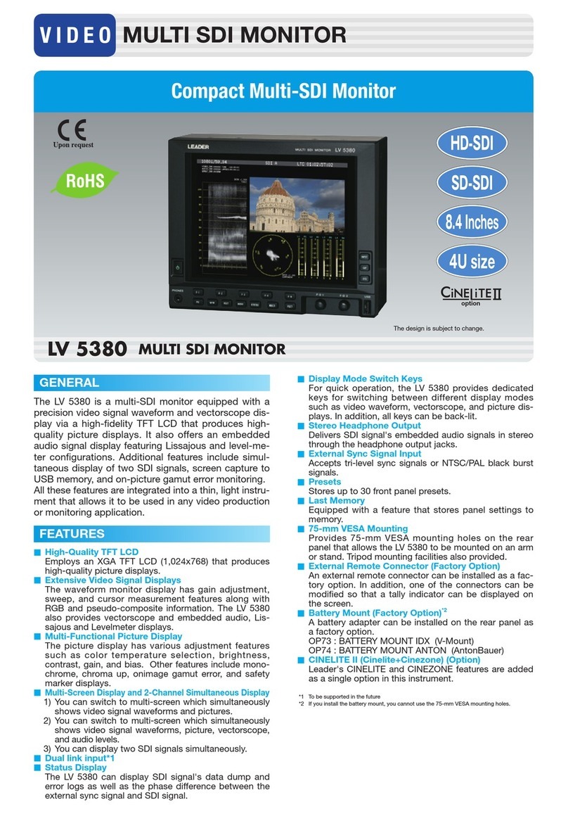
Leader LV 5380 User manual

Leader
Leader LV 5380 OP72 User manual

Leader
Leader LV 5800 User manual

Leader
Leader LV5600 Series Installation guide

Leader
Leader LV 5490 User manual

Leader
Leader LBO-51MA User manual

Leader
Leader LV 5490 User manual

Leader
Leader LV 58SER21 User manual

Leader
Leader LV 5333 User manual

Leader
Leader LV5307 User manual