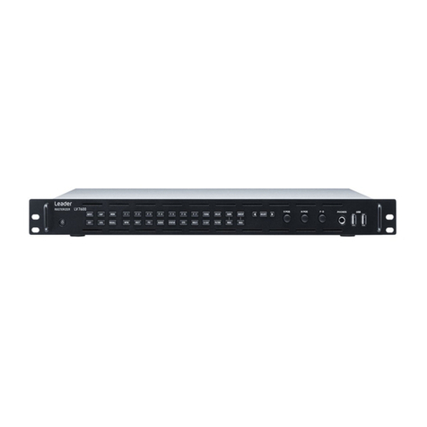
Leader LV5307 User manual

a
LV5307 SDI/HDMI Monitor
Instruction Manual
USORESTRITO

b
USORESTRITO

c
TABLE OF CONTENTS
GENERAL SAFETYSUMMARY I
1 INTRODUCTION
������������������������������������������������������������������������������������������������������
1
1
�
1 Scope of
W
arranty
���������������������������������������������������������������������������������������������������������������������
1
1
�
2 Operating Precautions
���������������������������������������������������������������������������������������������������������������
1
1
�
2
�
1 About Standby Mode
�����������������������������������������������������������������������������������������������������������������
1
1
�
2
�
2 Mechanical Shock
����������������������������������������������������������������������������������������������������������������������
1
1
�
2
�
3 Electrostatic Damage
����������������������������������������������������������������������������������������������������������������
1
1
�
2
�
4
W
arming Up
�������������������������������������������������������������������������������������������������������������������������������
1
1
�
2
�
5 Backup Battery
��������������������������������������������������������������������������������������������������������������������������
2
1
�
2
�
6 About the LCD Panel
�����������������������������������������������������������������������������������������������������������������
2
1
�
3 About
T
rademarks and Licenses
�����������������������������������������������������������������������������������������������
2
2 PRODUCT FEATURES
�������������������������������������������������������������������������������������������
3
2
�
1 General
��������������������������������������������������������������������������������������������������������������������������������������
3
2
�
2 Control Panel
�����������������������������������������������������������������������������������������������������������������������������
4
2
�
3 Basic Information
�����������������������������������������������������������������������������������������������������������������������
5
2
�
3
�
1 Initial Setup
��������������������������������������������������������������������������������������������������������������������������������
5
3 CONNECTIONS
�������������������������������������������������������������������������������������������������������
6
3
�
1 Connecting to SDI signals (3Gbps ~ 270 Mbps)
�����������������������������������������������������������������������
6
3
�
2 Connecting to HDMI signals
������������������������������������������������������������������������������������������������������
7 3
�
3
Connecting to Component Input Signals (1
�
0 Vpp - Y with Sync; 0
�
7 Vpp - Pb Pr)
�������������������
8 3
�
4
Connecting to Composite Input Signals (1
�
0 Vpp with Sync)
����������������������������������������������������
8
4 MENU FEATURES
���������������������������������������������������������������������������������������������������
9
4
�
1 Video
������������������������������������������������������������������������������������������������������������������������������������������
9
4
�
1
�
1 Color
T
emp
�����������������������������������������������������������������������������������������������������������������������������������
9
4
�
1
�
2 Brightness
����������������������������������������������������������������������������������������������������������������������������������
9
4
�
1
�
3 Contrast
�������������������������������������������������������������������������������������������������������������������������������������
9
4
�
1
�
4 Color
������������������������������������������������������������������������������������������������������������������������������������������
9
4
�
1
�
5 Color Only
��������������������������������������������������������������������������������������������������������������������������������
10
4
�
1
�
6 NTSC Setup
�����������������������������������������������������������������������������������������������������������������������������
10
4
�
1
�
7 Max Bright
��������������������������������������������������������������������������������������������������������������������������������
10
4
�
2 Aspect Menu
����������������������������������������������������������������������������������������������������������������������������
10
4
�
2
�
1 Scan
�����������������������������������������������������������������������������������������������������������������������������������������
10
4
�
2
�
2 Aspect
��������������������������������������������������������������������������������������������������������������������������������������
10
4
�
2
�
3 Anamorphic
������������������������������������������������������������������������������������������������������������������������������
11
4
�
2
�
4 Zoom Mode
������������������������������������������������������������������������������������������������������������������������������
11
4
�
2
�
5 H/V Delay
���������������������������������������������������������������������������������������������������������������������������������
12
4
�
2
�
6 Still
�������������������������������������������������������������������������������������������������������������������������������������������
12
4
�
3
A/V
Scope
��������������������������������������������������������������������������������������������������������������������������������
12
4
�
3
�
1 Scope Position
�������������������������������������������������������������������������������������������������������������������������
12
4
�
3
�
2
W
aveform Enable
��������������������������������������������������������������������������������������������������������������������
12
4
�
3
�
3
W
aveform Source
��������������������������������������������������������������������������������������������������������������������
12
4
�
3
�
4 Vector Enable
��������������������������������������������������������������������������������������������������������������������������
12
4
�
3
�
5 Audio Level Meter
��������������������������������������������������������������������������������������������������������������������
12
4
�
3
�
6 Scope Blend
����������������������������������������������������������������������������������������������������������������������������
13
4
�
4 Settings Menu
��������������������������������������������������������������������������������������������������������������������������
13
4
�
4
�
1 OSD
�����������������������������������������������������������������������������������������������������������������������������������������
13
4
�
4
�
2 Load Sys Default
���������������������������������������������������������������������������������������������������������������������
13
USORESTRITO

d
4
�
4
�
3 Bklight Dimming
�����������������������������������������������������������������������������������������������������������������������
13
4
�
4
�
4 Misc
�����������������������������������������������������������������������������������������������������������������������������������������
13
4
�
5 Advanced Menu
�����������������������������������������������������������������������������������������������������������������������
14
4
�
5
�
1 Input Output
�����������������������������������������������������������������������������������������������������������������������������
14
4
�
5
�
2
T
imecode
���������������������������������������������������������������������������������������������������������������������������������
14
4
�
5
�
3 Source Alias
�����������������������������������������������������������������������������������������������������������������������������
14
4
�
5
�
4 UMD
�����������������������������������������������������������������������������������������������������������������������������������������
15
4
�
5
�
5 System Info
������������������������������������������������������������������������������������������������������������������������������
15
4
�
5
�
6 H Flip
���������������������������������������������������������������������������������������������������������������������������������������
15
4
�
5
�
7
Test Pattern
������������������������������������������������������������������������������������������������������������������������������
15
4
�
6 Function Keys
��������������������������������������������������������������������������������������������������������������������������
15
4
�
7 Marker
��������������������������������������������������������������������������������������������������������������������������������������
16
4
�
8 Handheld
���������������������������������������������������������������������������������������������������������������������������������
16
4
�
8
�
1 DSLR Scale
�����������������������������������������������������������������������������������������������������������������������������
16
4
�
8
�
2 Peaking
������������������������������������������������������������������������������������������������������������������������������������
16
4
�
8
�
3 Peaking Sensitivity
�������������������������������������������������������������������������������������������������������������������
16
4
�
8
�
4 Peaking Color
��������������������������������������������������������������������������������������������������������������������������
16
4
�
8
�
5 Peaking Blinking
����������������������������������������������������������������������������������������������������������������������
16
4
�
8
�
6 False Color
������������������������������������������������������������������������������������������������������������������������������
16
4
�
8
�
7 False Color U/L
������������������������������������������������������������������������������������������������������������������������
17
4
�
8
�
8 False Color L/L
������������������������������������������������������������������������������������������������������������������������
17
4
�
8
�
9 False Color Palette
������������������������������������������������������������������������������������������������������������������
17
4
�
8
�
10 Limit Emphasis
������������������������������������������������������������������������������������������������������������������������
17
4
�
8
�
11 False Color Blink
����������������������������������������������������������������������������������������������������������������������
17
4
�
8
�
12 Limit Blink
��������������������������������������������������������������������������������������������������������������������������������
17
5 OTHER INFORMA
TION
������������������������������������������������������������������������������������������
18
5
�
1 Accessories
�����������������������������������������������������������������������������������������������������������������������������
18
5
�
2 Specifications
���������������������������������������������������������������������������������������������������������������������������
19
USORESTRITO

I
GENERAL SAFETY SUMMARY
■Read This before Using the Instrument
This instrument should only be used by persons with sufficient knowledge of electronics who
thoroughly understand the contents of this manual
�
This instrument is not designed or manufactured for households or ordinary consumers
�
If unqualified personnel are to use the instrument, be sure the instrument is handled under the
supervision of qualified personnel (those who have electrical knowledge). This is to prevent the
possibility of personal injury or damage to the instrument
�
■The contents of this manual contain specialized terminology and may be difficult to understand. If you
have any questions about the contents of this manual, please contact your local LEADER agent.
■Symbols and Terms
The following symbols and terms are used in this instruction manual and on the instrument to indicate
important warnings and notes
�
< Symbol >
This symbol appears in this instruction manual and on the instrument to indicate an area
where improper handling could result in personal injury, damage to the instrument, or
malfunction of the instrument or devices connected to it
�
When you encounter this symbol on the instrument, be sure to refer to the information in this
instruction manual that corresponds to the area that the symbol marks
�
< Term >
WARNING
Ignoring the precautions that this term indicates could lead to death or serious injury
�
< Term >
CAUTION
Ignoring the precautions that this term indicates could lead to personal injury or damage
to
the instrument
�
USORESTRITO

II
GENERAL SAFETY SUMMARY
Readthewarningsandinformationbelowthoroughlytoavoiddeath,personalinjury,anddamageanddeterioration
of
the instrument
�
WARNING
■Warning Concerning the Case and Panels
Do not remove the instrument’s case or panels for any reason
�
T
ouching the internal
components of the instrument could lead to fire or electric shock.
Also, do not allow foreign materials, such as liquids, combustible matter, and metal, to
enter the instrument
�
T
urning the instrument on when such materials are inside it could
lead to fire, electric shock, damage to the instrument, or some other accident.
■Installation Environment
•Operating Temperature Range
Use this instrument in a 0 to 40 C environment
�
Using the instrument with its vents blocked
or in a high temperature environment could lead to fire.
Drastic changes in temperature, such as might be caused by moving the instrument
between two rooms with different temperatures, can damage the instrument by
causing condensation to form within it
�
If
there is a possibility that the instrument has
condensation within it, wait for approximately 30 minutes before turning on the power.
•Operating Humidity Range
Use this instrument in an environment whose relative humidity is 85% or less where there
is no threat of condensation forming
�
Also, do not operate this instrument with wet hands. Doing so could lead to electric shock
or fire.
•Do Not Operate in an Explosive Atmosphere
Using this instrument in an environment where flammable gases, explosive gases, or steam
is emitted or stored cold lead to an explosion or fire. Do not use the instrument in such
an environment
�
•Do Not Insert Foreign Materials
If foreign materials, such as metal, flammable objects, or liquid are allowed into the
instrument (through the vents for example), fire, electric shock, damage to the instrument,
or some other accident may result
�
■If YouNotice Something Wrong during Operation
If you notice smoke, fire, a strange smell, or something else that is wrong with the
instrument while you are operating it, stop operation immediately. Failing to do so could lead
to fire. Turn off the power switch, and remove the power cord from the outlet. Aftermaking
sure that fire has not spread anywhere, contact your local LEADER agent.
USORESTRITO

3
GENERAL SAFETY SUMMARY
WARNING
CAUTION
■
Cautions Concerning the Input and Output Connectors
To avoid damaging the instrument, only apply signals to the input connectors that conform
to the specifications in this instruction manual. Do not short or apply external voltage to the
output connectors
�
Doing so could damage the instrument
�
■
Cautions Concerning the Ethernet Port
When you are connecting the instrument to the communication provider’s equipment,
connect to the Ethernet port through a hub that is authorized for use in the country that
you are using the instrument in
�
■
W
arning Concerning the Power Source
Do not use a power source with a voltage other than the rated power source voltage for the
instrument. Doing so could lead to fire.
Confirm the voltage of the power source before you connect the power cord to it.
Only use a power source whose frequency is 50/60 Hz
�
Use a power cord that is appropriate for the voltage of the power source. Also, use a power
cord that meets the safety standards of the country that you are using it in
�
Using a power cord that does not meet the standards could lead to fire. If the power cord is
damaged, stop using it, and contact your local LEADER agent. Using a damaged power
cord could lead to electrical shock or fire.
When removing the plug from the power outlet, do not pull on the cord. Pull from the plug.
■
W
arnings Concerning Grounding
The instrument has a ground terminal to protect the user and the instrument from electric
shock
�
Ensure that the instrument is properly grounded for safe operation
�
■
W
arnings Concerning the Panel
Do not apply a strong shock to the panel, cut it with sharp metal, or damage it in any similar
manner
�
USORESTRITO

4
GENERAL SAFETY SUMMARY
■Calibration and Repairs
This instrument has been carefully examined at the factory to ensure that its performance is in
accordance with the standards. However, because of factors such as parts wearing out over time,
the performance of the instrument may degrade. Toensure stable performance, we recommend that
you have the instrument calibrated regularly. Also, if the instrument malfunctions, repairs are
necessary. For repairs and calibration, contact your local LEADER agent.
■Routine Maintenance
When you clean the instrument, remove the power plug from the outlet.
Do not use thinner or benzene when you clean the instrument’s case, panels, or knobs. Doing so
could lead to paint chipping and the corrosion of plastic components. Toclean the case, panels, and
knobs, use a soft cloth with mild detergent, and wipe gently. While cleaning, make sure that foreign
materials, such as water and detergent, do not enter the instrument. If liquid or a metal object enters
into the instrument, fire or electric shock may result.
■About the European WEEE Directive
This instrument and its accessories are subject to the European WEEE Directive
�
Follow the applicable regulations of your country or region when discarding this instrument or its
accessories
�
F
ollow the EU Battery Directive when discarding
t
he bat
t
eries
t
hat you removed
f
rom this
instrument
�
(WEEE stands for
W
aste Electrical and Electronic Equipment)
�
Follow the warnings and precautions that have been listed in this section to use the instrument correctly
and safely
�
Precautions are also contained in various other sections of this instruction manual
�
T
o use the
instrument correctly, be sure to follow those precautions as well.
If you have any questions or comments about this instruction manual, please contact your local LEADER
agent
�
USORESTRITO

1
1.
INTRODUCTION
Thank you for purchasing this LEADER instrument. To use this instrument safely, read this
instruction manual thoroughly, and make sure that you know how to use the instrumentproperly.
If some point about the operation of this instrument is still unclear after you have readthis
instruction manual, refer to the contact information on the back cover of the manual to contact
LEADER, or contact your local LEADER agent.
After you have finished reading this manual, keep it in a convenient place so that you can refer to it
when necessary
�
1
�
1 Scope of
W
arranty
This LEADER instrument has been manufactured under the strictest quality control guidelines
�
LEADER shall not be obligated to furnish the following free services during the warranty period:
1. Repair of malfunction or damages resulting from fire, natural calamity, or improper
voltage applied by the user
�
2. Repair of an instrument that has been improperly repaired, adjusted, or modified by
personnel other than a factory-trained LEADER representative
�
3
�
Repair of malfunctions or damages resulting from improper use
�
4
�
Repair of malfunctions caused by devices other than this instrument
�
5
�
Repair of malfunctions or damages without the presentation of a proof of purchase
or receipt bill for the instrument
�
1
�
2 Operating Precautions
1
�
2
�
1 About Standby Mode
CAUTION
Even if you press the power switch to turn off this instrument, the instrument remains in standby mode
as long as the power cord is connected to the outlet. In standby mode, some of the internal circuits
operate and may generate heat. Unless necessary, keep the power cord disconnected from the outlet.
1
�
2
�
2 Mechanical Shock
This instrument contains sensitive components, so it may be damaged if it is dropped or otherwise
exposed to a strong shock
�
1
�
2
�
3 Electrostatic Damage
Electronic components can be damaged by static discharge
�
Static electricity can build up in the core
wire of a coaxial cable. Before connecting a coaxial cable to the instrument, short the core wire of the
cable with the external conductor
�
1
�
2
�
4
W
arming Up
Toensure more accurate measurements, turn on the instrument approximately 30 minutes before you
intend to use it to allow its internal temperature to stabilize
�
USORESTRITO

2
1
�
2
�
5 Backup Battery
This instrument has a last-memory feature. When you turn the power on, the instrument starts with
the panel settings that were in use the last time that it was turned of
f
�
If
the backup battery is out of
power, the message “The last memory feature is disabled.” will be displayed, and this feature will no
longer work
�
To continually use the last-memory feature, we recommend that you replace the backup battery with a
new one every five years after you purchase the instrument. You cannot replace the backup battery
yourself
�
Contact your local LEADER agent
�
1
�
2
�
6 About the LCD Panel
The LCD panel used in this product is made of glass. Therefore, it can break when the product is
dropped or exposed to impact
�
There may be a small number of pixels in the LCD panel that do not light or are always on
�
Note that
this is not a malfunction
�
The LCD panel supports a large number of video signals
�
SDI input signals are displayed
synchronously on the LCD. Therefore, images may appear to flicker on the waveform and
picture displays
�
In addition, the input SDI signal is temporarily stored in frame memory and is loaded by using the
LCD display synchronization signal—which is not synchronized with the input SDI signal. Therefore,
because frame skip—which skips over frames in the memory—and frame repeat—which readsthe
same frames of the memory twice—occur, the image may appear toflicker.
1
�
3 About
T
rademarks and Licenses
The company and product names in this document are trademarks or registered trademarks of their
respective holders
�
USORESTRITO

3
2.
2
�
1
PRODUCT FEATURES
General
Integrated Converter
Multi-Format Signal
3G-SDI (3Gb/sec 4:4:4 HD)
SDI-HDMI Loop Through
12-Bit Internal Processing
2K Input Capability
Peaking / Focus Assist
DSLR Scaling
Cinezone (False Colors Filter)
Under Monitor Display
Menu Jog Control
Integrated active SDI-HDMI and HDMI-SDI converter
allows the trasnparent conversion of HD to HDMI signal or
conversion of HDMI back to HD format
�
Leader monitors are compatible with various sources
including:
- HDMI (compatible with DVI)
- SDI signals: 3G (425 A/B), HD, SD
- CVBS (composite) and YPbPr (component)
�
SMPTE 425 compliant HD display that supports frame rates
of 50.60 in 1080p, 1080i, and 720p.
Supports full SMPTE 425 signal conversion transparency
from SDI to HDMI with
test
and measurement overlays
�
Allows for color temperature and gamma encoding changes
to
be implemented quickly
�
Active Video Looping supports
full 1080p/60 frames on the HDMI output
�
2K content can be displayed on this Leader monitor
without the loss of HD signal by converting and
downscaling the content
�
Peaking filter shows if the image is out of focus in difficult
wide full range DSLR shots by highlighting areas that are out
of focus with a cross stripe pattern
�
Actively scales live video images to reduce the black areas of
the screen to allow for a full screen 16:9 image
�
Color filtering allows uses to display different areas of the
images as different colors to set portions of the scene as over
or under exposed
�
UMD function displays ancilliary data at the bottom of the
screen
�
Jog dial on the front of the monitor enables users to control
all features
�
Waveform Monitor
VectorscopeMonitor
Pixel to Pixel Mapping
De-Embedded Audio LevelMeter
Aspect Format Markers
Gamma Encoding Select
Time Code
On screen display of video levels with respect to time, used
to
calibrate multiple camera setups and vertical blanking level
and color burst
�
On
screen display of chrominance information in Cb and Cr
channels
�
Display can be opaque or solid against the visual
display
�
1:1 Pixel mode displays the original image resolution without
scaling to match a certain resolution or an aspect ratio
�
De-embedded audio selected out
�
Auto sensing to display
three range meter of up to 16 channels
�
4:3, 14:9, 15:9, 16:9, etc. area, line, safety, center markers
display
�
Range from 1
�
0 to 3
�
0 users selectable
�
Factory default
setting is 2
�
8
�
T
ime code reader displays embedded LTC or VITC formats
�
H/V Delay
RJ-45 Remote Control
V
iew the blanking area and synchronize signals by displaying
the horizontal and vertical intervals in the center
of
the screen
�
Plug in your RJ-45 connector to the back of the monitor and
communicate with other Leader monitors (RS-484 control
/
T
ally Light control)
�
USORESTRITO

4
2
�
2 Control Panel
FRONT
2. Tally display 3. Speaker
4. Source select
6. Rato scan choice
8. Main menu open
10. EXIT
12. UP
14. DOWN
5. Function key F1
7. Function key F2
9. Function key F3
11. Function key F4
13. Function key F5
15. Function key F6
REAR
14. Power LED
16. Menu control Jog
1. Component [ Pr ], CVBS
3 in
3. Component [ Pb ], CVBS 2 in
5. Component [ Y ], CVBS
1 in
7. Audio in L
9. PC Audio in
11. HDMI in
2. SDI signal in
4. SDI signal out
6. Composite out
8. Audio in R
10. PC Audio out
12. HDMI out
13. V mount
14. RS-485 IN
15. RS-485 OUT
16. DC 12V Power in
17. XLR Power in
18. On/Off switch
1.
Mount
USORESTRITO

5
2
�
3 Basic Information
2
�
3
�
1 Initial Setup
When the monitor is initially turned on and connected to your source, follow the instructions below:
•Selecting a source: Toselect your source, please press the SOURCE button. Turn the main
control jog to make your choice, and click the jog to lock the selection.
Fact
ory default is HDMI (Please keep
t
his
st
ep if you are connected
t
o a HDMI
source)
�
•Menu Control: Press the main control jog on the front of the monitor for 2 seconds to enter
or exit the menu
�
T
urn the jog to move around the menu
�
Click the jog to
make your selection
�
Main jog allows users to move one step at a time
�
If
you wish to move back to previous step in the menu, press the jog for two
seconds. If you want to exit the menu and restart, press the EXIT button
depending on where you are in the menu tree
�
•Function Key: The monitor is set with the following DEFAULT FUNCTION KEYS:
F1
Blue / Mono
F2
H/V Delay
F3
Max Bright
F4
SDI Output
F5
HDMI Output
F6
Aspect
Users can program 6 function buttons on the front panel by followingthese
steps:
Menu Function Key Function Key #
All features in the monitor can be programmed in one of these six function
keys
�
USORESTRITO

6
3.
CONNECTIONS
3
�
1 Connecting to SDI signals (3Gbps ~ 270 Mbps)
SIGNAL FORMATS
INPUT
OUTPUT
SMPTE 425M (3G)
4:2:2
1080 60p
1080 50p
SMPTE 425M (3G)
4:4:4
720 24p
720 25p
720 50p
720 60p
1080 23
�
98p
1080 23
�
98psf
1080 24p
1080 25p
1080 30p
1080 50i
1080 60i
SMPTE
260M (1
�
5G)
4:2:2
1035 60i
SMPTE
274M (1
�
5G)
4:2:2
1080 24psf
1080 24p
1080 23
�
98p
1080 23
�
98psf
1080 25p
1080 30p
1080 50i
1080 60i
SMPTE
296M (1
�
5G)
4:2:2
720 60p
720 50p
720 30p
720 25p
720 24p
USORESTRITO

7
3
�
2 Connecting to HDMI signals
SIGNAL FORMATS
INPUT
OUTPUT
1080 60p
1080 50p
720 24p
720 25p
720 50p
720 60p
1080 24p
1080 25p
1080 30p
1080 50i
1080 60i
1035 60i
1080 24psf
1080 24p
1080 25p
1080 30p
1080 50i
1080 60i
720 60p
720 50p
720 30p
720 25p
720 24p
720 x 487 60i
720 x 507 60i
800 x 600
1024 x 768
1280 x 768
1360 x 768
1920 x 1080
1920 x 1200
USORESTRITO

8
3
�
3 Connecting to Component Input Signals (1
�
0 Vpp - Y with Sync; 0
�
7 Vpp - Pb Pr)
INPUT SIGNAL FORMATS
LV5307 MONITOR
480 60p
576 50i
576 50p
720 50p
720 60p
1080 50i
1080 60i
1080 50p
1080 60p
3
�
4 Connecting to Composite Input Signals (1
�
0 Vpp with Sync)
INPUT SIGNAL FORMATS
LV5307
NTSC
PAL
SECAM
USORESTRITO

9
4.
MENU FEATURES
4
�
1 Video
4
�
1
�
1 Color
T
emp
Main Video Color Temp
Select your preferred color temperature settings
[ User, 9300K, 7500K, 6500K ]
RED Gain, GREEN Gain, BLUE Gain
Adjusts R, G, B gain
Selectable level between [ 0min ~ 100max ]
RED Bias, GREEN Bias, BLUE Bias
Adjusts R, G, B Bias or Offset
Selectable between [-50min ~ 50max ]
COLOR COPY TO
Used to copy USER COLOR TEMP to 6500K, 7500K or 9300K
* IMPORTANT: Once user color temp overwrites the factory
default value of 6500K, 7500K or 9300K, it will apply PERMANENT
change and monitor reset will NOT restore the factory default
values
�
4
�
1
�
2 Brightness
Main Video Brightness
Adjusts the brightness (offset)
�
Selectable level between [ 0min ~ 100max ].
Shortcut by clicking the main control jog one time
�
4
�
1
�
3 Contrast
Main Video Contrast
Adjusts the contrast
�
Selectable level between [ 0min ~ 100max ]
Shortcut by clicking the main control jog 2 consecutive times
�
4
�
1
�
4 Color
Main Video Color
Selectable level between [ 0min ~ 100max ]
Shortcut by clicking the main control jog 3 consecutive times
�
USORESTRITO

10
4
�
1
�
5 Color Only
Main Video Color Only
Select your preferred color type [ Red, Green, Blue, Mono ]
4
�
1
�
6 NTSC Setup
Main Video NTSC Setup
Adjusts IRE value under NTSC mode between
OFF
(0 IRE) and
ON (7
�
5 IRE)
�
4
�
1
�
7 Max Bright
Main Video Brightness
Enabling this feature changes the brightness to maximum level
(100)
�
Disabling this feature will apply the previous brightness level
�
4
�
2 Aspect Menu
4
�
2
�
1 Scan
Main Aspect Scan
This product supports various scan modes [ Zeroscan, Underscan,
Overscan ]
ZEROSCAN
Zooms in/out of the image
without changing theaspect
ratio
UNDERSCAN
Zooms in/out of the image
without changing the aspect
ratio. Also, it displays the data
at the top of the horizontal
blanking edge
OVERSCAN
Zooms in/out of the image to
96% of its original size without
changing the aspect ratio
4
�
2
�
2 Aspect
Main Aspect Aspect
Used to change the aspect ratio between [fullscreen, 16:9, 4:3, 1:1 ]
USORESTRITO

11
FULLSCREEN:
Enlarges the aspect
ratio of the picture to fit
the entire screen
�
4:3 : Cuts left and right
of the original image to
fit to 4:3 aspect ratio
16:9 : Stretches the
image in “4:3 mode” to
fit to 16:9 aspect ratio.
1:1 : Pixel mapping
of
the original image
�
This feature is
available only when
the size
of
the original
image is bigger than
the screen size
�
4
�
2
�
3 Anamorphic
Main Aspect Anamorphic
Select your preferred anamorphic type among 17 options
�
4
�
2
�
4 Zoom Mode
Main Aspect Zoom Mode
Used to magnify the image up to 230% of the originaldisplay
between [ zoom, Pixel to Pixel, Disable ]
PIXEL
TO
PIXEL:
If
the resolution of the input signal is greater than
the LV5307, then only the area equivalent to the monitor resolution
will be displayed in this mode
�
ZOOM:
Zoom Ratio: Used to change the zoom ratiobetween
[ 0min ~ 230max ]
H Position: Adjusts the horizontal position ofimage
[ 0 left ~ 50 right ]
V Position: Adjusts the vertical position ofimage
[ 0 top ~ 50 bottom ]
1
1
�
37:1
10
2
�
35:1
2
1
�
50:1
11
2
�
37:1
3
1
�
55:1
12
2
�
39:1
4
1
�
60:1
13
2
�
40:1
5
1
�
66:1
14
2
�
55:1
6
1
�
75:1
15
2
�
59:1
7
1
�
85:1
16
2
�
76:1
8
2
�
00:1
17
3
�
56:1
9
2
�
20:1
USORESTRITO

12
* IMPORTANT: When Zoom Mode is activated, the main control jog operates for zoom feature.
Shortcut for brightness, contrast and color by clicking the jog once. Two clicks or three
clicks change to zoom ratio, H position, and V position.
4
�
2
�
5 H/V Delay
Main Aspect H/V Delay
Used to monitor the blanking area [ Off, H/V Delay, H Delay,
V Delay ]
4
�
2
�
6 Still
Main Aspect Still
Used to freeze the displayed image [ Off, On ]
4
�
3
A/V
Scope
4
�
3
�
1 Scope Position
Main A/V Scope Scope Position
Used to change the position of scopes
[ Right/Bottom, Right/Top, Left/Bottom, Left/Top ]
4
�
3
�
2
W
aveform Enable
Main A/V Scope Waveform Enable
Used to turn on waveform on the screen [ On, Off ]
4
�
3
�
3
W
aveform Source
Main A/V Scope Waveform Source
Users can choose to display scopes of theirneeds
[ Luma, Cb, Cr, Luma + Cb + Cr ]
4
�
3
�
4 Vector Enable
Main A/V Scope Vector Enable
Used to turn on the vectorscope on the screen [ On, Off ]
4
�
3
�
5 Audio Level Meter
Main A/V Scope Audio Level Meter
Used to turn on 16 channel audio level meter on top of the
screen [ On, Off ].
USORESTRITO
Table of contents
Other Leader Monitor manuals

Leader
Leader LV 5380 User manual

Leader
Leader LV 58SER21 User manual

Leader
Leader LV 5490 User manual

Leader
Leader LV 5380 OP72 User manual

Leader
Leader LV 5333 User manual

Leader
Leader LV 5800A User manual

Leader
Leader LV5600 Series Installation guide

Leader
Leader LV 5800 User manual

Leader
Leader LV 5490 User manual

Leader
Leader LBO-51MA User manual