Leb Electronics LB7 User manual
1
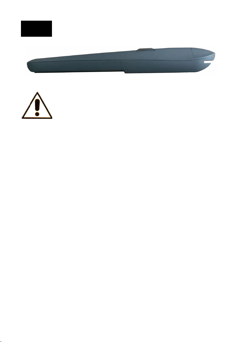
Avvertenze
1) Leggere attentamente le istruzioni prima di iniziare l'installazione;
2) Conservare queste istruzioni per necessità future;
3) Il dispositivo è stato realizzato appositamente per automatizzare cancelli
a battenti. Ogni altro uso è da considerarsi improprio e quindi vietato;
4) La struttura del cancello deve essere sufficientemente robusta e le
cerniere devono funzionare in modo efficiente e non devono esserci attriti
tra parti mobili e parti fisse;
5) Non installare l’operatore in atmosfera esplosiva;
6) Le parti meccaniche di costruzione del cancello devono essere conformi
alle norme EN12604 e EN12605;
7) L'installazione deve essere conforme alle norme EN12453 e EN12445;
8) Prima di agire sull’impianto, verificare che la tensione di rete sia sconnessa;
9) L’impianto dev’essere alimentato tramite un interruttore magnetotermico
bipolare da 6 A e tramite un interruttore differenziale con soglia 0,03 A;
10) Verificare che l'impianto di messa a terra sia realizzato a regola d’arte e
che le parti metalliche siano ad esso collegate;
11) Si declina ogni responsabilità in merito alla sicurezza e al funzionamento
qualora vengano utilizzati componenti non originali;
12) Il cancello deve essere dotato di un fermo meccanico in posizione di
chiusura, saldamente ancorato a terra, per evitare che il cancello si
muova oltre la corretta posizione di chiusura;
13) Non modificare in alcun modo i componenti dell'automazione;
14) L'installatore dovrà fornire le informazioni relative allo sblocco manuale
di emergenza e dovrà consegnare all'utente il manuale istruzioni;
15) Non permettere a bambini o adulti di sostare vicino al cancello mentre è
in funzione;
16) Tenere i telecomandi lontano dalla portata dei bambini.
LB7
Versione manuale V1.0
Operatore elettromeccanico per cancelli a battente
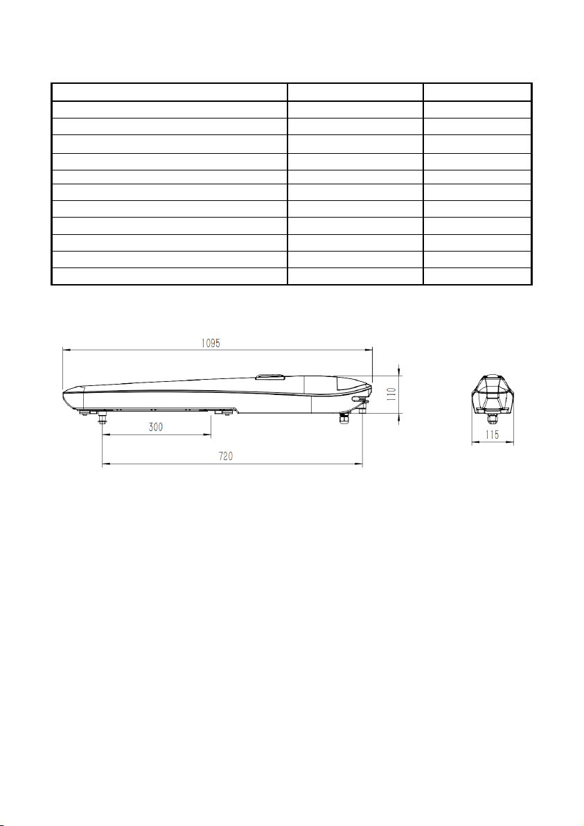
Specifiche tecniche LB7
2
Verifiche preliminari
Prima di procedere con l'installazione di LB7, verificare i seguenti punti:
- Verificare che cancello sia solido e che scorra senza attriti;
- Assicurarsi che i cardini del cancello siano efficienti e ben lubrificati;
- Assicurarsi che siano presenti dei fermi meccanici in apertura e chiusura;
- Verificare i collegamenti della messa a terra;
- Assicurarsi che il peso e le dimensioni del cancello siano all’interno dei
limiti di impiego ottenibili dalla tabella che segue.
Dati tecnici LB7-24 LB7-230
Alimentazione motore elettrico 24 Vdc 230 Vac - 50 Hz
Corrente nominale assorbita 5 A1,2 A
Corsa perno di trascinamento 300 mm 300 mm
Velocità perno di trascinamento 18 mm/sec. 16 mm/sec.
Spinta 2500 N2000 N
Grado di protezione IP44 IP44
Condensatore motore (interno) /10uF
Temperatura di funzionamento da -20 a +50°C da -20 a +50°C
Ciclo di lavoro 50% 70%
Dimensioni 1095*115*110 mm 1095*115*110 mm
Peso 12 Kg 12,5 Kg
Dimensioni (mm)
3
Nella tabella seguente sono riportate le misure di riferimento per
l'installazione dell'operatore LB7.
INSTALLAZIONE
Assicurarsi che il dispositivo funzioni entro i limiti di impiego ottenibili dalla
seguente grafica:
IMPORTANTE: è obbligatorio installare due fermi meccanici per stabilire il
limite di apertura (K1) e il limite di chiusura (K2) dell'anta.
REGOLE GENERALI: si consiglia di non scegliere valori di “A” e “C” troppo
diversi tra loro, in modo da garantire un movimento regolare dell'anta.
Possibilmente limitare la differenza tra A e C a 4 cm.
Aumentando la quota “A” si aumenta l'angolo di apertura, si riduce la spinta
dell’anta e si aumenta la velocità periferica.
Aumentando la quota “C” si riduce l'angolo di apertura, aumenta la spinta
dell'anta e si riduce la velocità periferica.
K1
Lunghezza
anta (m)
Peso
anta (Kg)
Lunghezza
anta (m)
5
4
3
2
1
0 100 200 300
Peso
anta (Kg)
LB7-24 LB7-230
90-
K2
Pilastro
Cardine
Anta
Apertura A (mm) C (mm)
90° 150 120
120° 150 70
4
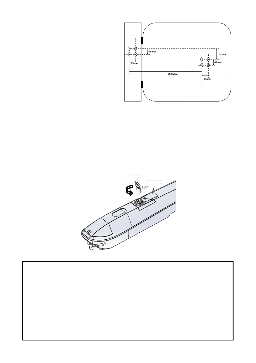
PROCEDURA
•Mettere le ante in posizione di
chiusura;
•posizionare la staffa posteriore
nella posizione corretta;
•fissare la staffa anteriore nella
posizione corretta;
•la distanza tra la staffa anteriore
e quella posteriore non deve
superare i 700 mm. Il dislivello è
di 52 mm.
Sblocco manuale
Lo sblocco manuale determina lo sgancio dell'operatore dall'anta,
consentendone lo spostamento manuale. È solitamente utilizzato in caso di
mancanza di tensione elettrica o di guasto dell'impianto. Lo sblocco avviene
tramite una chiave che deve essere custodita dall'utente in un luogo sicuro e
facilmente raggiungibile. Per sbloccare l'anta agire nel modo seguente:
•Far scorrere il coperchio di protezione verso la parte anteriore dell’operatore;
•Inserire la chiave e ruotarla di 180° in senso antiorario.
Data, 07 Aprile 2022
DICHIARAZIONE DI CONFORMITA’ CE (Direttiva macchine 2006/42/CE)
Il produttore dichiara che LB7 è conforme ai requisiti delle direttive
LVD 2014/35/CE e R&TTE 2014/30/CE.
Dichiara inoltre che sono state applicate le seguenti norme armonizzate:
EN 301489-1 V1.8.1 EN 60335-1+A11+A1+A12+A2+A13+A14+A15
EN 301489-3 V1.4.1 EN 60335-2-103+A11
EN 300220-1 V2.1.1 EN 62233
EN 300220-2 V2.1.2 EN 1245
Chiave Coperchio

1
Warnings
1)Read the instructions carefully before starting the installation;
2) Keep these instructions for future needs;
3) The device has been specifically designed to automate swing gates.
Any other use is to be considered improper and therefore prohibited;
4) The gate structure must be strong enough and the hinges must work
efficiently and there must be no friction between moving and fixed parts;
5) Don’t install the operator in an explosive atmosphere;
6) The mechanical construction parts of the gate must comply with the
EN12604 and EN12605 standards;
7) The installation must comply with the EN12453 and EN12445 standards;
8) Before working on the system, check that the mains voltage is disconnected;
9) The system must be powered by a 6 A bipolar magnetothermic switch and
by a differential switch with a 0.03 A threshold;
10) Check that the earthing system is made correctly and that the metal
parts are connected to it;
11) We decline all responsibility regarding safety and operation if not-original
components are used;
12) The gate must be equipped with a mechanical stop in the closed position,
firmly anchored to the ground, to prevent the gate oversteps the correct
closed position;
13) Don’t modify the automation components in any way;
14) The installer must provide the information relating to the emergency
manual release and must give the user the instruction manual;
15) Don’t allow children or adults to stand close the gate while it is in operation;
16) Don’t allow children to operate the remote controls.
LB7
Manual version V1.0
Electromechanical operator for swing gates

LB7 - Technical features
2
Preliminary checks
Before proceeding with the LB7 installation, check the following points:
- Check that the gate is solid and that it slides without friction;
- Make sure that the gate hinges are efficient and well lubricated;
- Make sure that there are mechanical stops for opening and closing;
- Check the earthing connections;
- Make sure that the weight and length of the gate are within the limits of use
which can be obtained from the following table.
Technical data LB7-24 LB7-230
Electric motor power supply 24 Vdc 230 Vac - 50 Hz
Nominal absorbed current 5 A1,2 A
Stroke of traction pivot 300 mm 300 mm
Speed of traction pivot 18 mm/sec. 16 mm/sec.
Thrust 2500 N2000 N
Protection degree IP44 IP44
Motor capacitor (internal) /10uF
Operating temperature from -20 to +50°C from -20 to +50°C
Working cycle 50% 70%
Dimensions 1095*115*110 mm 1095*115*110 mm
Weight 12 Kg 12,5 Kg
Dimensions (mm)

3
The following table shows the reference measurements for installing the LB7
operator.
INSTALLATION
Make sure that the device works within the limits of use which can be
obtained from the following graphic:
IMPORTANT: it’s mandatory to install two mechanical stops to establish the
opening limit (K1) and the closing limit (K2) of the leaf.
GENERAL RULES: it’s advisable not to choose values for “A” and “C” that
are too different from each other, in order to guarantee regular movement of
the leaf. Possibly limit the difference between A and C to 4 cm.
Raising the value "A" increases the opening angle, reduces the thrust of the
leaf and increases the peripheral speed.
Raising the value "C" reduces the opening angle, increases the thrust of the
leaf and reduces the peripheral speed.
K1
Length
leaf (m)
Weight
leaf (Kg)
Length
leaf (m)
5
4
3
2
1
0 100 200 300
Weight
leaf (Kg)
LB7-24 LB7-230
90-
K2
Pillar
Hinge
Leaf
Opening A (mm) C (mm)
90° 150 120
120° 150 70
4
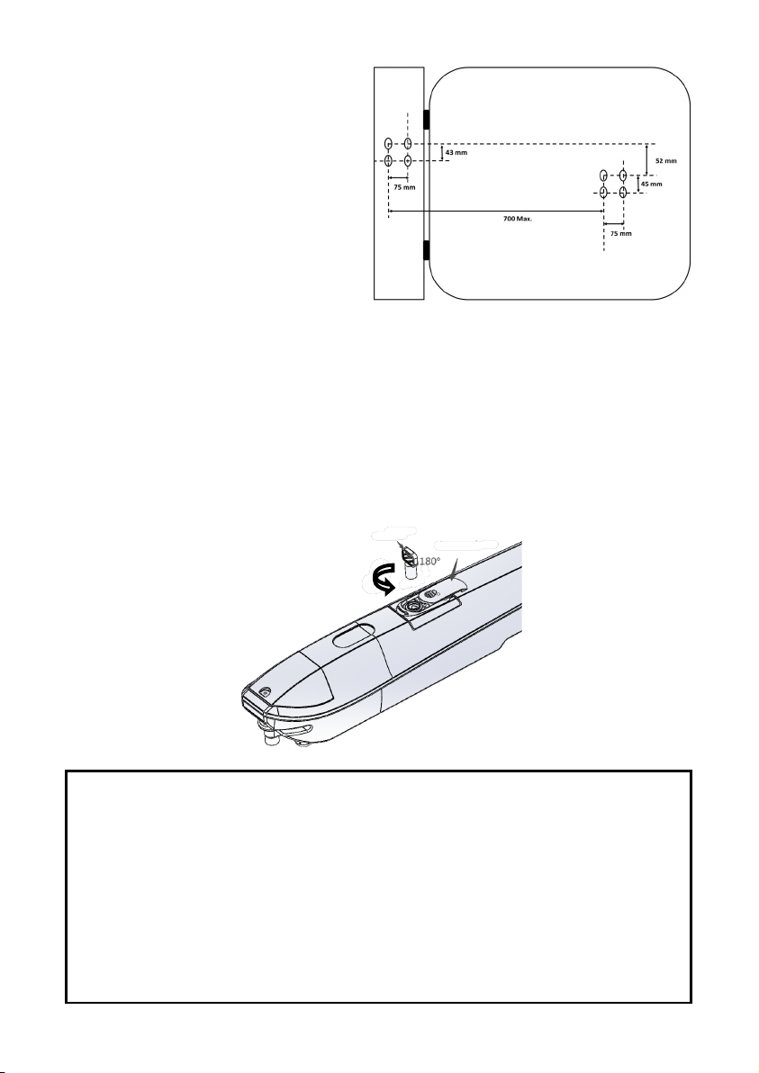
PROCEDURE
• Put the leaf in the closed position;
• place the rear bracket in the correct
position;
• fix the front bracket in the correct
position;
• the distance between the front and
rear bracket should be less than
700 mm. The difference in height is
52 mm.
Manual unlocking
The manual unlocking determines the release of the operator from the leaf,
allowing it to be moved manually. It’s usually used in the event of a power
failure or system breakdown. Unlocking takes place by a key which must be
kept by the user in a safe and easily accessible place. To unlock the leaf,
proceed as follows:
• Slide the protective cover towards the front of the operator;
• Insert the key and rotate 180° counterclockwise.
Date, 07 April 2022
DECLARATION OF CONFORMITY (Machine Directive 2006/42/EC)
The manufacturer declares that LB7 complies with the requirements of the
LVD 2014/35/EC and R&TTE 2014/30/EC directives.
It also declares that the following harmonized standards have been applied:
EN 301489-1 V1.8.1 EN 60335-1+A11+A1+A12+A2+A13+A14+A15
EN 301489-3 V1.4.1 EN 60335-2-103+A11
EN 300220-1 V2.1.1 EN 62233
EN 300220-2 V2.1.2 EN 1245
Key Cover
This manual suits for next models
2
Table of contents
Languages:
Other Leb Electronics Gate Opener manuals


