Lehner Liftechnik Delta User manual

Web: www.lehner-lifttechnik.at Tel: +4372783514
Email: office@lehnerlifttechnik.at Mobile: +436641612980
Installation Manual
DELT
P l a t f o r m s t a i r l i f t

DELTA
Installation Manual
Edition July 2013
DELT
∆
∆∆
∆
platform lift page 1 of 24
Table of content
OBSERVE THE FOLLOWING POINTS BEFORE INSTALLATION! 2
INSTALLATION OF THE RAILS 3
LOAD AND FIXINGS OF RAILS AND PILLARS 5
INSTALLATION MATERIAL FOR FIXING OF THE RAIL 6
OVERVIEW PLATFORM 7
INSTALLATION OF THE PLATFORM ONTO THE RAIL 8
INSTALLING OF THE CHARGING STATION/LIMIT ASSEMBLY 10
ADJUSTING OF THE CONTROL CAMS 11
LAST CHECKS BEFORE USING THE STAIRLIFT 12
STANDARD ELECTRICAL COMPONENTS OF THE SIDEWALL 13
ELECTRICAL COMPONENTS OF THE LOWER CARRIAGE 14
OVERVIEW OF THE PLATFORM MECHANICS 14
ADJUSTMENT OF THE PLATFORM INCLINATION 16
ADJUSTMENT OF THE LOADING RAMPS 17
ADJUSTMENT OF MOTOR CURRENT 17
ADJUSTMENT OF THE REMOTE CONTROLS 18
DISMANTLE THE PLATFORM FLOOR 19
ADJUSTMENT OF THE OVERLOAD SWITCH 20
TROUBLESHOOTING 21
OVERVIEW OF THE SWITCHBOARD LED FUNCTIONS 23

DELTA
Installation Manual
Edition July 2013
DELT
∆
∆∆
∆
platform lift page 2 of 24
Observe the following points before installation!
Installation teams must have a general knowledge in:
• working on electric controls
• asic mechanical engineering and providing adequate fixation of the rails and pillars
• reading and understanding circuit diagrams and wiring schematics
The following points are necessary for the installation:
• Have a complete tool kit on hand for mechanical and electrical works
• Check eforehand what fixing materials (screws, anchor olts, adhesives) are
required for the proper fixing of the rails to the wall or the pillars to the floor. These
materials are not included in the delivery! The installation company is responsi le
for the fixing of the rail to the wall or the pillars to the floor/steps!
• Check the packages for shipping damage and missing parts efore ringing the lift
to the site. Take pictures of damaged parts as soon as these are discovered to
provide proof for warranty claims.
• A team of 2 qualified technicians is necessary to install the lift.
Bring the platform to the upper landing efore fixing the rails in order to prevent damage to
the rail and platform during transport on the staircase! The platform can only e engaged
from the upper end of the rail.
Caution: The large platform is heavy; it weighs approximately 120 kg. A dolly might e
necessary to transport the platform up the steps.
The following tools will be required to finish the installation successfully:
A complete toolset for
mechanical and electrical works
Voltmeter
Drilling machines
Drills, thread cutter
Fixing material
Water lever with angle
indication

DELTA
Installation Manual
Edition July 2013
DELT
∆
∆∆
∆
platform lift page 3 of 24
Fasten all
screws that
connect the
rackets to
the rail
Bracket
Upper rail
Use an anlge
water level
Installation of the rails
The rails can e fixed directly to the wall or on pillars that are fixed to the staircase.
Step 1: If there are 2 rail sections, com ine oth
rail sections. See illustration.
If there are more than 2 rail sections the 3
rd
rail
sections has to e added once the first 2 are
installed on the staircase.
Step 2: Set the approximate angle etween the
rail and the racket according to the angle given
in the installation drawing.
Then fasten all screws that connect the rackets
to the upper and the lower rail.
Bracket
Charging station
and mechanical
limit assem ly
Upper cam
Pillar

DELTA
Installation Manual
Edition July 2013
DELT
∆
∆∆
∆
platform lift page 4 of 24
Step 3: First fix the upper racket to the wall or to the upper pillar (pillars have the serial
letters stamped on the ase). The required dimensions for the first fixing point are given in
the drawing – see dimension X1 and Y1 in example drawing elow:
Step 4: Adjust the correct angle of the rail. Now check the necessary clearance
(dimensions D in illustration) etween the lower rail and the step noses. In case the rail
angle must e changed to get the correct clearance etween rail and step then the angle
of the lower platform carriage needs to e changed.
Step 5: If the actual measurements correspond with the clearance dimensions on the
layout drawing fix the remaining rackets to the walls or to the pillars.
Step 6: Clean any de ris from the rails

DELTA
Installation Manual
Edition July 2013
DELT
∆
∆∆
∆
platform lift page 5 of 24
Load and fixings of rails and pillars

DELTA
Installation Manual
Edition July 2013
DELT
∆
∆∆
∆
platform lift page 6 of 24
Installation material for fixing of the rail
For concrete walls: For concrete walls:
For concrete walls: For rick walls:
For rick walls: Adhesive 2 components glue for rick wall installation

DELTA
Installation Manual
Edition July 2013
DELT
∆
∆∆
∆
platform lift page 7 of 24
Overview platform

DELTA
Installation Manual
Edition July 2013
DELT
∆
∆∆
∆
platform lift page 8 of 24
Installation of the platform onto the rail
If you wish to reduce the weight of the complete unit, you can dismantle the platform floor
from the carriage. Please see chapter “Changing the platform floor” for the detailed
explanation. If you can manage to lift the platform with 2 or more people continue as
outlined here elow:
Step 1: The upper charging station and the upper cam
have to e removed from the rail
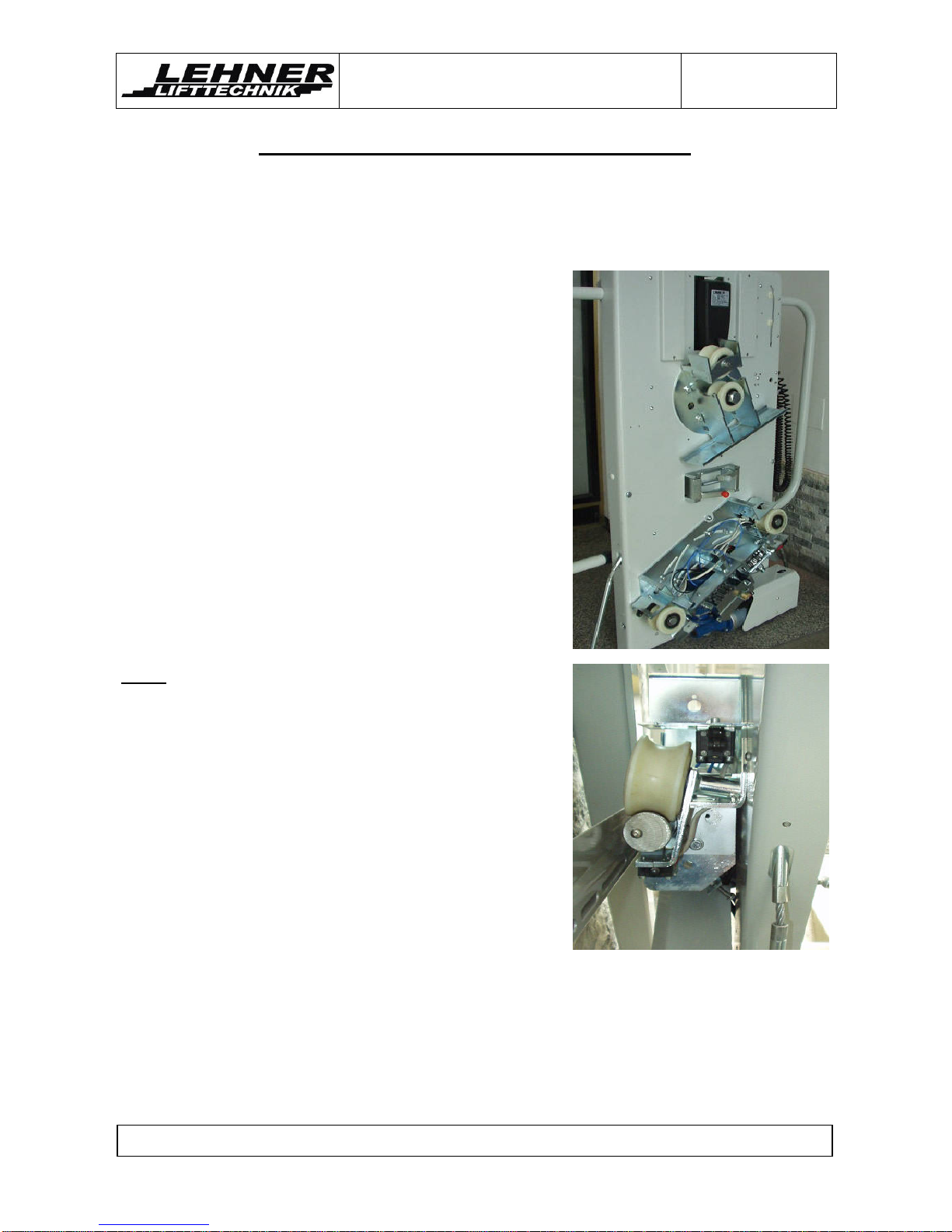
Step 2: Dismantle the covers from the upper and lower
carriages. The ackside of the sidewall should look as
shown on the picture eside.
Step 3: Carefully lift the carriage on upper rail end,
guiding the upper carriage rollers onto the upper rail.
Then the lower carriage will e approached carefully to
the lower rail.
Step 4: Insert the hand wheel into the drive motor,
loosen the reak of the motor and turn the hand wheel
into the downwards direction.
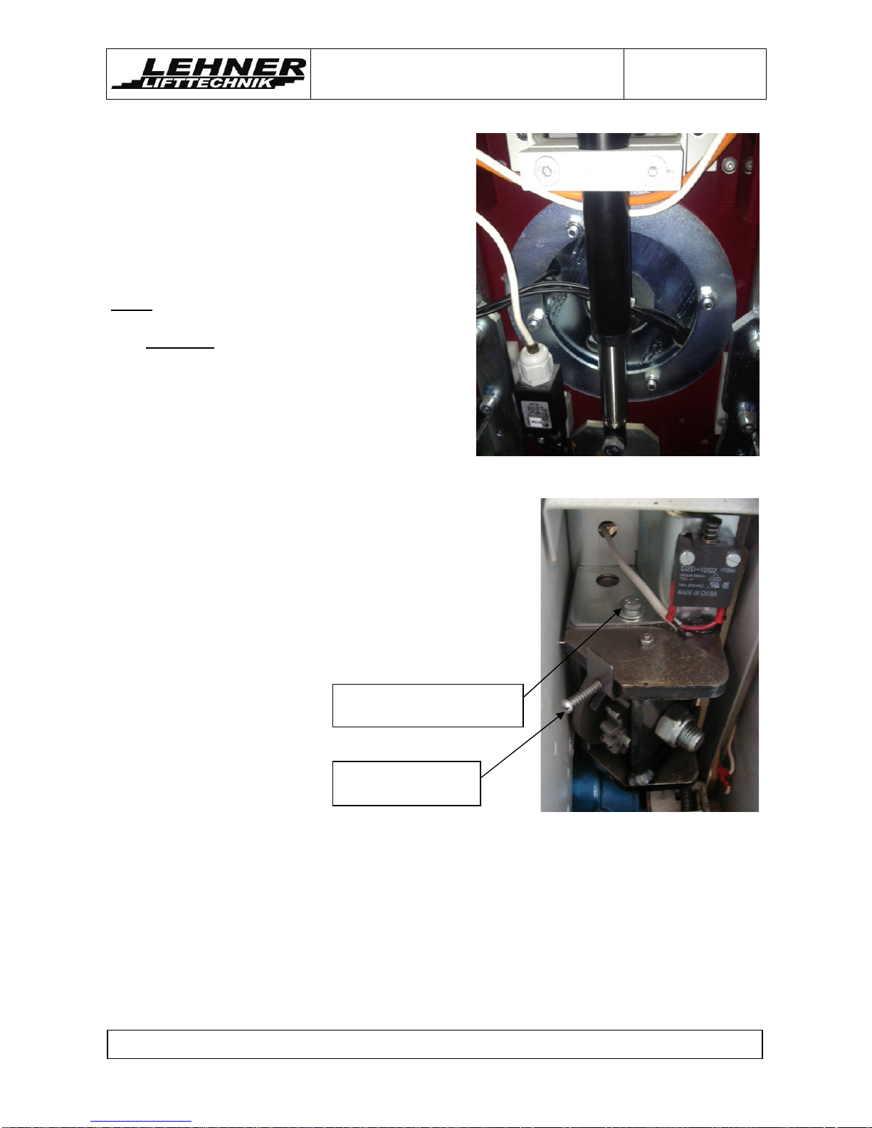
Note: Always watch the interference of the tooth wheels
(drive wheel and overspeed governor) and the rack.
Have a look at the illustration to the right – if it does not
go smoothly dismantle the platform again and insert it
new! Do not use the motor for riding the carriage onto
the rails! The tooth wheels of the drive and the
overspeed governor can e damaged!
Step 5: Install the atteries on the ackside of the
carriage (in case they have een removed). Check if the
attery is connected correctly and switch on the main
power switch.
Step 6: Open the platform carefully so that the arrier arms and platform floor are
horizontal. Now you can drive the platform further down y using the handset on spiral
ca le.

DELTA
Installation Manual
Edition July 2013
DELT
∆
∆∆
∆
platform lift page 9 of 24
Use this screw for fixing the
overspeed governor
Lever to trigger the
overspeed governor
Step 7: Open the upper and lower frontal covers
of the carriage. At delivery of the unit the upper
carriage will e movea le (can rotate). This will
facilitate the process of engaging the platform
onto the rails. After engaging the platform the
upper carriage has to e fastened – see elow.
Adjust the upper carriage to the same angle as
the lower carriage and the rail.
Note: After adjusting the angle of the upper
carriage, fix the four nuts of the upper carriage.
This must not e forgotten!!!
Step 8: Run the carriage once up and down on
the railway and check if the overspeed governor
is adjusted well. There should e a constant gap
etween the rack and the guide holes in the
overspeed governor. If not adjust the overspeed
governor y loosening the fixing screw.
Step 9: Reinstall the charging ramp and the clams for
un locking of the arrier arms to the upper end of the
railway. Reinstall all covers on the carriages.

DELTA
Installation Manual
Edition July 2013
DELT
∆
∆∆
∆
platform lift page 10 of 24
Installing of the charging station/limit assembly
The position of the charging stations/limit assem ly has to e adjusted so the limit
switches on the lower carriages are pressed y the mechanical stop at the correct spot.
Connect the stations according to the electric
diagram. The positive connection goes to the
charging ramps (copper material). The negative
connection goes to the rail. Make sure there
cannot e a short circuit etween the copper and
the rail. This could destroy the charger! Connect the
upper and the lower copper charging ramp with a
single phase ca le. This ca le can run ehind the
steel profile under the lower rail.
Fix the charging station with the limit assem ly onto the steel profile in the upper and lower
landing. Fine adjust limit switches S27 and S28 if necessary with the slot hole under the
carriage covers.
The
plastic uffers on the lower end of the ackside
of the carriage should touch down slightly on the
ottom in the lower stop position. The lower
limit assem ly should e placed accordingly!
In the upper stop position the platform should
e in one line with the landing height, so the
wheelchair driver can leave the platform
horizontally, without any ramp inclination!
Install the battery charger at any convenient
place close to the upper or lower charging
stations. Make sure there is no collision etween the attery charger and the moving
platform in case of wall fixing of the rail.
Plastic uffers should just
touch down on the ottom!
Fine adjustment of the stop
can e made y moving the
limit switch fixing
Fit the limit assem lies on the upper
and lower landing to the steep plate.
Loosen screws and
move plate up or
down
Positive Negative

DELTA
Installation Manual
Edition July 2013
DELT
∆
∆∆
∆
platform lift page 11 of 24
Control cam
Adjusting of the control cams
Adjust the control cams - the levers for unclamping the arrier
must e in the middle of the control cams when the platform
arrives in the stop position.
Important: The charging lever must hit the charging ramps
efore the lever for unclamping of the arrier arms hit the
control cams! Otherwise the lift would stop and can only e
moved ack y the hand wheel.
The upper lever for unclamping is responsi le for the left
arrier and, the lower lever is responsi le for the right arrier!
Caution: Do not mount two control cams in the upper stop
position! Else the lower arriere can e opened and the user
may fall out of the platform!!
Add the red colored plastic hood on the lever for the upper arrier – this
indicates for the emergency rescue of passengers, as descri ed in the user manual!
If the control cams and the charging stations with the mechanical limits are correctly
adjusted then the unit should e perfectly set for operation. In case the lift is not running
perfectly there might further adjustments e necessary. Please check through the
following pages.

DELTA
Installation Manual
Edition July 2013
DELT
∆
∆∆
∆
platform lift page 12 of 24
Last checks before using the stairlift
Before going into operation, check again the correct measurements and fixings and make
sure there can e no collision etween the platform and the staircase or any other
o stacle. Make sure that the travel clearances are correct and all strut fasteners tightened.
Caution: Do not ride on the unit until the fasteners are tightened.
• With the charging station, the limit locks and the control cams in place, run the
carriage up to the top of the system and ack while checking the travel clearances
of the carriage.
• When the landing is uneven and the loading ramp does not rest properly on the
floor, adjust the ramps on the platform once more.
Make the following checks efore handing over the unit to the client:
Check all fastenings of the rail to the wall/pillars and pillars to the steps
Check connections of rail parts for strength and proper alignment
Check clearance of the platform to the steps and opposite walls under full load
Check function of directional safety switches: safety ottom underpan, loading
ramps, landing stop limit switches
Check ultimate limit switches function
Check arrier arm safety switch function
Check proper connection of charging stations; make sure there is no possi ility for a
short circuit
Check proper platform position at lower stop under full load; make sure safety
ottom is not pressed efore lower stop limit switch is pressed and check proper
alignment of loading ramps
Check arrier arms for horizontal alignment
Check all platform functions: Drive up and down with handset (open platform) and
hall calls (closed platform), opening and closing of platform in landing stations.
Check key switch and stop utton operation
Check proper fixing and position of all platform covers
Caution: The installation team is responsi le for a proper carrying out of the installation.
The unit has to e tested for secure working including its environment (structural
influences)! Are there differences against the drawing, other influences or o vious defects
which prevent a save working it is not allowed to set the lift into operation.
If any malfunctions are occurring or adjustments need to e made, please refer to the
following pages for more detailed information.

DELTA
Installation Manual
Edition July 2013
DELT
∆
∆∆
∆
platform lift page 13 of 24
Standard electrical components of the sidewall
Platform
closed switch
Barrier arm
open switch
Ramp switch
Barrier arm
safety switch
Platform
motor
Platform
open switch
Barrier arm
safety switch
Ramp switch
Barrier arm
horizontal
switch
Control
oard
Safety ottom
switches

DELTA
Installation Manual
Edition July 2013
DELT
∆
∆∆
∆
platform lift page 14 of 24
Electrical components of the lower carriage
Limit switch
Ultimate
limit switch
By-pass
switch
Overspeed
switch
Limit switch
Ultimate
limit switch
Levers for
un locking
of arrier
arms
Batteries

DELTA
Installation Manual
Edition July 2013
DELT
∆
∆∆
∆
platform lift page 15 of 24
Overview of the platform mechanics
Actuator slider
Hook for arrier
arms opening
Ramp
activation
Barrier arm
linkage
Ramp
linkage
Ring
screw
Central platform
mechanism plate
Lateral contact ar
Switch for lateral
contact ar
Switch for lateral
contact ar
Ball earing
linkage
Mechancial stop
for folding of
platform
Un locking of
arrier arms

DELTA
Installation Manual
Edition July 2013
DELT
∆
∆∆
∆
platform lift page 16 of 24
Adjustment of the platform inclination
To adjust the platform horizontally, change the
adjustment screws as shown in the picture. Check in
loaded condition! Counter the adjusting screw with
the counter nut after successful adjustment.
Caution: Check if both adjusting screws are
supporting the platform!
After changing the platform inclination please check
the platform mechanism:
Between the hook and the slider should
e around 2mm gap. This can e
adjusted y moving switch S11m.
S11p must e properly pressed when
platform is open (it must click when
pressed). Otherwise adjust.
S11o must e pressed when platform is
closed. Otherwise adjust.
Between the main earing and the
platform sliding mechanism a minimum
distance of 1-2mm must e given. This
can e adjusted y changing the length
of the all earing connection etween
the platform and the carriage. This is
important so that mechanical force of the
platform in an unfolded position is not
directly carried forward to the mechanical
parts inside the platform, ut rather held
y the adjusting screws!
If arrier arms are not horizontal open
the screw shown in the illustration, adjust
the arrier and lock the adjustment with
the screw again.
Adjustment
Main earing Extend all
earing
1-2mm
distance
Necessary 2mm gap
Hook
S11o
S11p
S11m
Slider
Barrier arm
adjustment

DELTA
Installation Manual
Edition July 2013
DELT
∆
∆∆
∆
platform lift page 17 of 24
main motor
(poti R40)
platform
actuator
(poti R50)
Adjustment of the loading ramps
Adjust the ramps to achieve a 45 ° angle etween the platform and ramp when the arrier
is in horizontal position. When the arrier is open, the ramp has to fit to the ottom of the
landing area. Also fix the ring at an angle of around 45° to the side of the ramp and at a
distance of around 2/3 inside the slot. This ensures est operation.
Check the loading ramps for proper operation. In folded and unfolded position of the
platform, the ramps are also used as safety pads. When fixing the ramp ensure that it still
can e pushed in order to activate the safety switches S12 and S13.
Adjustment of motor currents
On the electronic oard you can adjust the
maximum current of the drive motor and the
maximum current of the platform actuator.
Adjusting the main motor:
Start on the lower landing with the full load
capacity on the platform and drive upwards.
While driving upwards, turn the potentiometer
(R40) to the right until the lift stops. Now the
maximum current is reached.
You have to turn ack the potentiometer (R40)
a little. Try several times to drive up with the full
load and the lift shouldn’t stop.
Adjusting the platform actuator
While closing the platform with the landing
control turn the potentiometer (R50) to the right
until the actuator stops.
You have to turn ack the potentiometer (R50)
a little. Close the platform again several times
and the actuator shouldn’t stop.
45°
45°
Best location of screw in distance of around 2/3
of slot length
and ring
turned
at 45° to
ramp side
2/3 of slot
length

DELTA
Installation Manual
Edition July 2013
DELT
∆
∆∆
∆
platform lift page 18 of 24
Adjustment of the remote controls
How to teach the transmitter
• The “teach-mode” can e initiated y pressing the utton S1 (Prog.) on the main
PCB (see picture elow) oard for minimum 1 second ut no more than 6 seconds
on the main oard.
[see picture]
• As soon as the utton will e unclasped, the receiver waits 5 seconds for valid
signals of the working-transmitter. If no transmitter will e recognized during this
time, the receiver goes ack into normal operation/mode.
Any utton has to e pressed during the time of 5 seconds y minimum 2 seconds.
• As soon as a transmitter is known and stored the receiver switches to the normal
operation/mode and shows the status of the utton on the USART.
• Additional transmitters have to e programmed in the same way.
How to delete a transmitter
• All stored working-transmitter can e deleted on the receiver y pressing the S1
(Prog.) utton for minimum 6 seconds on the main oard.

DELTA
Installation Manual
Edition July 2013
DELT
∆
∆∆
∆
platform lift page 19 of 24
Dismantle the platform floor
• Dismantle the all earing connection etween sliding mechanism and platform
• Disconnect platform rod connection for sidewall
• Dismantle safety under-pan of the platform
• Disconnect spring inside platform floor. You might need to manually compress the
spring in order to uninstall the connection. Make sure that the connection etween
the spring and the earing is correctly put together afterwards. The connection
metal parts have a slight end. It is important for reassem ly that they are put ack
in the same way.
• Disconnect the electrical wiring etween the platform floor and the sidewall
• Disconnect fixing screw from the treaded pinhole of main platform hinge earing
• Remove the main earing pin and take off the platform floor
Take out main
earing pin
Disconnect spring
Disconnect platform rod
Loosen all
earing
Take out spring Disconnect fixing
screw and wiring
Bend in
metal part
Table of contents
Other Lehner Liftechnik Stairlift manuals
Popular Stairlift manuals by other brands

AmeriGlide
AmeriGlide Titan Incline Lift Installation

Bruno
Bruno ELITE SRE-2010 Operator's manual

AmeriGlide
AmeriGlide Rave 2 installation manual

Harmar Mobility
Harmar Mobility Pinnacle Owner's manual and warranty information

Lehner Lifttechnik
Lehner Lifttechnik DELTA user manual

Lippe Lift
Lippe Lift T80 operating instructions