Lehner Lifttechnik OMEGA - F User manual

Austria, 4724 Neukirchen/W, Salling 8 Tel: +4372783514
Email: office@lehnerlifttechnik.at Mobil: +436641612980
Installation Manual
MEGA –F
s t a i r l i f t

OMEGA Installation Manual
Edition July 2013
Omega platform lift page 1 of 46
CONTENTS
OBSERVE THE FOLLOWING POINTS BEFORE INSTALLATION!....................................3
STEP 1. –INSTALLATION OF THE GUIDE RAILS..............................................................4
STEP 2. INSTALLATION OF THE DRIVE BOX....................................................................6
STEP 3. INSTALLATION OF THE TENSION AND SUPPORT ROPE SYSTEM..................6
Install the tension rope.................................................................................................................... 8
Install the support rope ................................................................................................................. 11
Detailed diagram of the rope fixing assembly to the platform sidewall....................................... 13
STEP 4. INSTALLATION OF THE PLATFORM ONTO THE RAIL/ROPE SYSTEM..........15
STEP 5. TIGHTENING AND CONNECTING THE ROPES .................................................16
STEP 6: ELECTRICAL CONNECTIONS.............................................................................16
STEP 7. MOUNTING THE MECHANICAL STOP STATION ASSEMBLY..........................18
ADJUSTMENT OF THE LOADING RAMPS .......................................................................20
STEP 8. PROGRAMMING THE UNIT .................................................................................21
Explanation of the menu ............................................................................................................... 22
Teach-in mode - Programming the drive speeds.......................................................................... 26
ERROR LIST AND EXPLANATION ....................................................................................29
FINAL CHECKS...................................................................................................................32
EMERGENCY OPERATION................................................................................................33
EXPLANATION OF ELECTRIC CONCEPT ........................................................................34
DRIVE UNIT.........................................................................................................................35
Overview drive unit control board................................................................................................ 36

OMEGA Installation Manual
Edition July 2013
Omega platform lift page 2 of 46
Buttons and Jumpers on drive unit control board....................................................................... 38
Main contactor control board (MCCB)........................................................................................ 39
PLATFORM CONTROL BOARD ........................................................................................39
Platform control board overview .................................................................................................. 40
Switches, buttons and jumpers on the platform control board ................................................... 40
CONFIGURATION OF THE REMOTE RADIO CONTROLS...............................................43
Version Schmidiger:...................................................................................................................... 43
Version TeleRadio:........................................................................................................................ 43
ADJUSTMENT OF THE PLATFORM INCLINATION..........................................................44
DISMANTLE THE PLATFORM FLOOR..............................................................................45
ADJUSTMENT OF THE OVERLOAD SWITCH ..................................................................46

OMEGA Installation Manual
Edition July 2013
Omega platform lift page 3 of 46
Observe the following points before installation!
Installation teams must have a general knowledge in
basic mechanical engineering and providing adequate fixation of the rails and pillars
reading and understanding circuit diagrams and wiring schematics.
In order to save time and energy, it is wise to be properly prepared before installing the
OMEGA-platform lift. The following points will assist in completing the installation efficiently
and on schedule:
Have a complete electrical and mechanical tool kit on hand.
Check beforehand what fixing materials (screws, anchor bolts, adhesives) are
required for the proper fixing of the rails to the wall or the pillars to the floor. These
materials are not included in the delivery! The installation company is responsible for
the fixing of the rail to the wall or the pillars to the floor/steps!
Have the correct on-site power supply set up using the correct fuses. The power
supply has to be connected to the motor box at the upper end of the rail.
Assemble a team of 2 technicians to mount the plant.
Check the packages for shipping damage and missing parts before bringing the
lift to the site.
Open the installation package (which is in the box of the OMEGA lift). Review the
enclosed Installation notes, if supplied. In some cases, additional components must
be brought to the site.
Refer to the tube layout drawing and familiarise yourself with the tube configuration.
The following tools will be required to finish the installation successfully:
A complete toolset for
mechanical and electrical works
Voltmeter
Drilling machines
Drills, thread cutter
Fixing material
Water lever with angle
indication

OMEGA Installation Manual
Edition July 2013
Omega platform lift page 4 of 46
Step 1. –Installation of the guide rails
The rail can either be fixed directly to the wall or to free standing pillars that are fixed
either to the steps, the side of the staircase or the ground floor. Generally the
following important measures are given to start the installation at the lower landing:
In case of support pillars, these have the serial letters
indicated in the drawing that are also stamped on the
pillar base plate in order to identify the correct pillar.
To facilitate fixing of pillars it helps to provisionally fix
the pillars with rope clams.
W –perpendicular distance step nose to underside of lower rail
X –floor to lower end of rail connection bracket (of center of
rail)
Y –first step to side of rail connection bracket
Z –floor to underside of lower rail

OMEGA Installation Manual
Edition July 2013
Omega platform lift page 5 of 46
Drill the mounting holes, starting at the bottom with
Pillar A and working up the system. In concrete, use
a 10 mm diameter masonry bit. Otherwise use a
dowel and drill a 12 mm hole!. When mounting in
wood, use a standard 6 mm wood drill. Pass the lag
bolt (screw materials like lag bolts, nuts, washers,
etc., are not included in Lehner-Lifttechnik delivery-
specification) through a washer, and screw it into the
end of a plug anchor. The anchor can then be
tapped into position using a small hammer. Avoid
spilling dust into the hole.
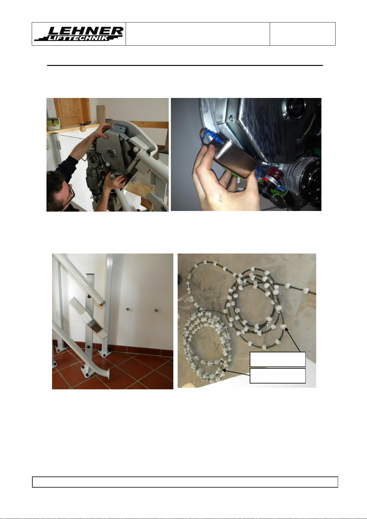
Check each connection for damage and lightly
grease both ends before joining the tube sections.
Fasten the connection with the splice bolts and nuts
provided.
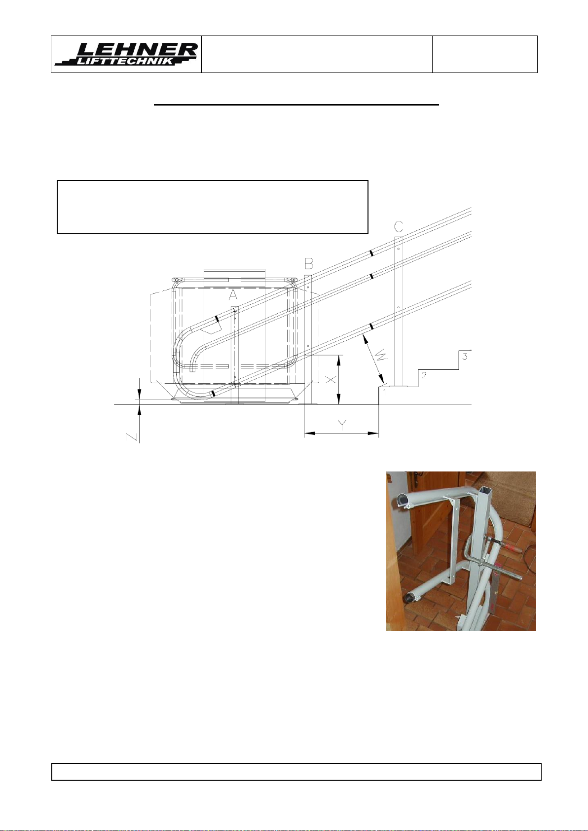
Check the clearance dimensions. Ensure that the
actual measurements correspond with the clearance
dimensions on the layout drawing.
Remember: Vertical clearances are measured from
the centreline of the tube (this is also the lower point
of the bracket on the railway) to the stair nose or to
the floor.
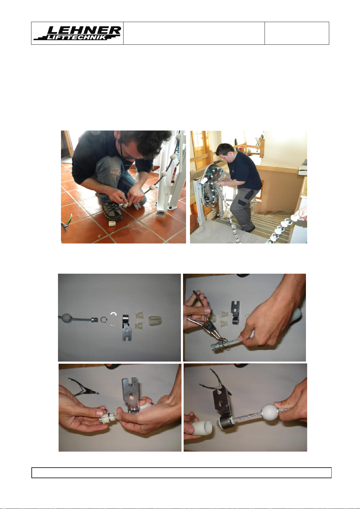
With the tubes in position, check all splice
connections for alignment. Note that the proper fit of
the splices is critical to ensure smooth lift operation.
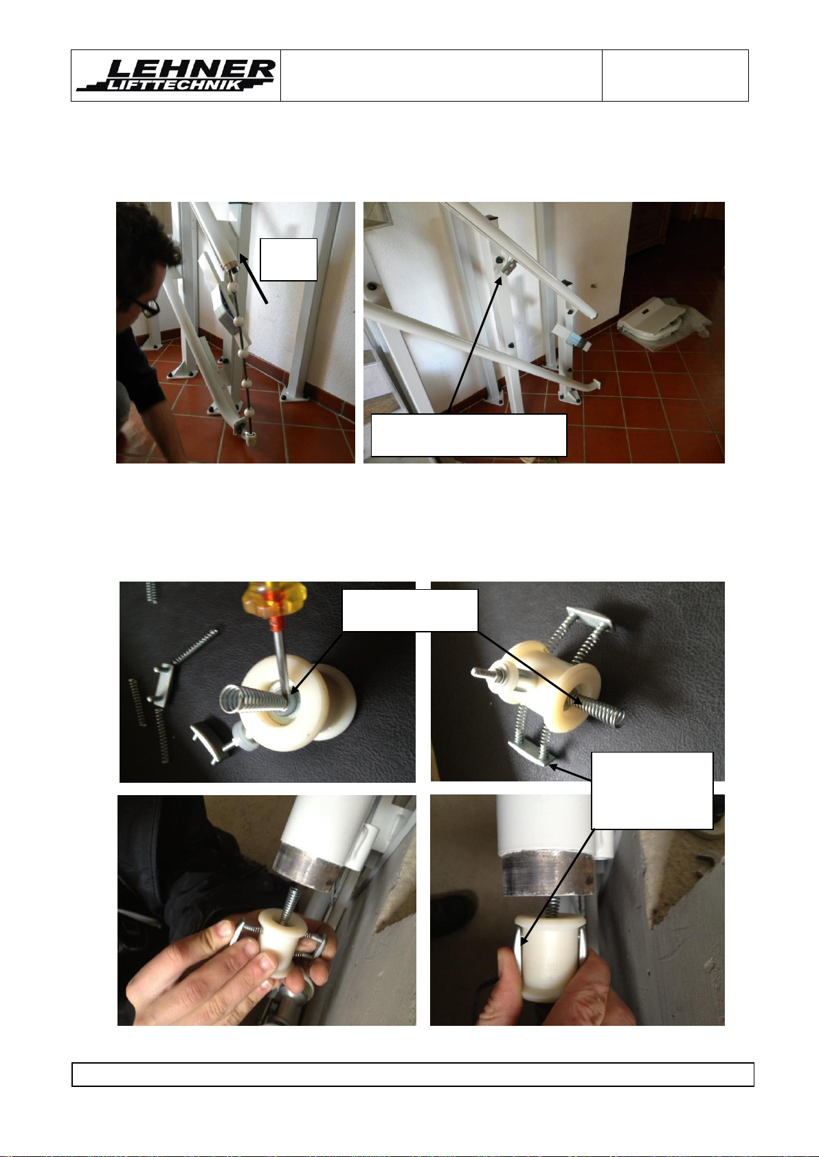
When fixing the lift in place, smooth out any
misalignment using shims behind the mounting
struts.
On longer lifts some discrepancies may occur. Try
to average them out while making a final check for
landing clearances, splice alignment and fit.
With the system in place, check that all struts and
support pillars are plumb. Use a water level for this
work!
Clean any debris from the inside of the tubes.

OMEGA Installation Manual
Edition July 2013
Omega platform lift page 6 of 46
Step 2. Installation of the drive box
When the tube system is anchored in place you can mount the drive box on the upper rail
end. Dismantle the cover as shown on the pictures below.
Drive wheel
Drive unit control board
Frequency
inverter
Current donator
Mains filter
Main power
switch
Main contactor
control board
Transformer
Emergency
hand wheel
Motor
Gear box
Upper ultimate
limit switch
Connect tube wire
Connect tension cable wire
Connect earth wire

OMEGA Installation Manual
Edition July 2013
Omega platform lift page 7 of 46
Tension rope
Support rope
Step 3. Installation of the tension and support rope system
Dismantle the mains filter form the drive wheel cover and also the complete drive
wheel cover from the drive wheel
Remove the over speed governor tube section at the bottom of the system and put
the complete rope on the bottom close to the upper motor and make sure it does not
get dirty.

OMEGA Installation Manual
Edition July 2013
Omega platform lift page 8 of 46
Install the tension rope
Start feeding the tension rope into the upper tube of the guide rail. Put as much
tension rope in the tube until the cable sticks out around 500mm on the lower rail
end of the upper tube.
The put the fixing bracket for the tension rope on the end of the tensions rope. See
the following page for detailed description.
Put the tension rope support connection onto the end of the tension rope.

OMEGA Installation Manual
Edition July 2013
Omega platform lift page 9 of 46
Pull back the tension rope inside the upper tube so that it stops where you want to
put the platform onto the rail. The fixing bracket of the tensions rope must be around
800mm above the ground floor level.
Add the current collector into the upper tube next to the fixing bracket. Make sure the
spring between the current collector and the upper fixing bracket is securely
attached to the current collector. This spring is responsible to make the electrical
contact between the tension cable and the platform control board.
Fix spring with
screwdriver on pin
Sliding contacts
connect rail with
control board
(electrical mass)
Pull
back
Upper fixing bracket 800mm
above lower floor level

OMEGA Installation Manual
Edition July 2013
Omega platform lift page 10 of 46
Please note that there is only 1 spring installed between the tension rope and
the current collector! There is not spring between the collector and the support
rope!!!
Schematic of the current collector:
Fixing bracket
Current collector
Spring

OMEGA Installation Manual
Edition July 2013
Omega platform lift page 11 of 46
Install the support rope
Feed the support rope into the lower tube and make sure the tension rope engages
well into the motor drive wheel. Make sure you put some cover on the lower floor so
the support rope does not get dirty when it gets out on the lower tube end.
Enter the lower rope into the over speed governor tube section. It might be
necessary to release the tension spring in order to facilitate entry of the rope into the
safety gear tube section. This spring later should be set to the same tension again
after the rope is installed!
The teeth of the wheel
have to engage into
metal elements of the
support rope
Tension spring

OMEGA Installation Manual
Edition July 2013
Omega platform lift page 12 of 46
Now you need to define the right length of the support rope. Approach the over
speed governor tube to the lower rail end to measure necessary support rope
element length. Check how many support elements of the tension rope have to be
removed so that the there is still enough space for the fixing bracket of the support
rope.
Overspeed
govener tube
Fixing bracket
for support rope
Measure
amount of
elements
Approach tube
to connection

OMEGA Installation Manual
Edition July 2013
Omega platform lift page 13 of 46
It is important that there are not too many support elements on the support rope as
then it is not possible to tension the cable. A gap of around 40mm between the last
support element and the fixing bracket of the support rope is ideal. This gap is later
reduced when the rope is tensioned!
Below it can be seen how the rope system should look before putting the platform
onto the rail.
Add the drive wheel cover and the mains filter again onto the drive wheel. This cover
must be fixed before the rope is tensioned!
Makes sure
elements are
pressed together
Gap of around
40mm before
tensioning the
cable
Fixing bracket of
support rope

OMEGA Installation Manual
Edition July 2013
Omega platform lift page 14 of 46
Detailed diagram of the rope fixing assembly to the platform sidewall
Please note that there is only 1 spring installed between the tension rope and the current
collector! There is not spring between the collector and the support rope!!!
Current
collector
Tension rope
Support rope
Connect wire
for support
rope on cable
clamp
Connect wire
for tube/rail
Connect wire
or tension
rope
Spring
connection
Make sure
plastic cap and
support rope is
placed as shown
here
Fixing
bracket
Fixing bracket

OMEGA Installation Manual
Edition July 2013
Omega platform lift page 15 of 46
Remove
conic
rollers
Step 4. Installation of the platform onto the rail/rope system
When the rope system is securely in place,
begin mounting the carriage. Complete the
following steps:
Bring the carriage to the bottom of the
tube system and unwrap it.
Remove the conical rollers from the
lower carriage.
Carefully lift the carriage into position,
guiding the upper carriage rollers onto
the upper tube. Ensure that the rope
fixing brackets fit between the bosses of
the upper carriage. Be careful not to
scratch the paint on the tubes.
Note: The carriage weighs about 90 kg,
so two people should install it to ensure
safety and avoid damage.
Tighten the screws that fix the carriage
to the fixing brackets of the tension and
support rope.
Install the conical rollers again on the
lower carriage.

OMEGA Installation Manual
Edition July 2013
Omega platform lift page 16 of 46
Connect to rail
wire
1. Put in the plastic isolation parts around rope
2. Add metal parts
without tightening!
3. Add tensioning device
4. Tension
the rope
by around
40mm
5. Tighten these bolts
after the rope is tensioned
6. Add 2 rope
clamps to fix rope
10. Connect
support rope
9. Connect
tension rope
wire
11. Put cover
first,…
12. Attach remaining rope in this
way
7. Add
plastic
tube
8. Connect to rail
Step 5. Tightening and connecting the ropes
Note: Make sure you reinstalled the cover of the drive box before tightening the rope!

OMEGA Installation Manual
Edition July 2013
Omega platform lift page 17 of 46
Tube and
earth wire
Tension
rope wire
Current
Donator
Ultimate upper
limit switch
Main power
switch
Step 6: Electrical connections
Connection the tension rope and the rail from the current collector, and the support
rope to the platform control board as described on the previous page.
Connect the tension rope wire from the drive
unit control board to the current donator on
the drive wheel and also connect the earth
and the tube wire to the rail next to the
current donator.
Connect the upper ultimate
limit switch to the drive unit
control board –connector
name “NESO”.
Connect the on-site main
power supply to the main
power switch on the drive
unit.

OMEGA Installation Manual
Edition July 2013
Omega platform lift page 18 of 46
Step 7. Mounting the mechanical stop station assembly
Adjustment of the limit switches and the control cams
Adjust the position of the control cam in reference to the limit switch device on the
rail. The bypass switch has to be activated before the levers for unblocking of the
barrier arms touch the control cams on the rail.
Levers for
unblocking of the
barrier arms at
the upper and
lower control cam
Bypass switch
S16 and lever
Landing stop
switches

OMEGA Installation Manual
Edition July 2013
Omega platform lift page 19 of 46
The bypass switch S 16 makes an
electrical bridge on the barrier arms safety
switches S14 and S15 and therefore
allows that the lift remains in function
although the barrier arms are
mechanically unblocked and electrical
safety circuit is interrupted. S16 has to be
activated before the control cams start to
unblock the barrier arms in each landing
station. Otherwise the lift will stop when
the barrier arms are unblocked, as thus
the barrier arm safety switches S14 and/or
S15 are pushed and the safety circuit is
interrupted!
In the upper stop position (and also
intermediate stop positions) the
platform floor should be at the
same level as the landings.
On the lower landing the carriage
should touch down slightly on the
bottom with both buffers located on
the lower end of the backside of the
carriage.
Run the carriage out of the
landings and back again. If the lift
does not stop in the correct
position, adjust it as necessary.
Adjust the ultimate limit
switch so that it is
properly aligned with the
activation pin on the
cover of the upper
carriage. The pin should
reach the switch in case
the normal limit switch
does not work.
Adjust the ultimate
limit switch and
the activation pins!
Activates
by-pass
Activates
limit switch
Deactivates
by-pass
Cam for
unblocking
of barrier
arm
Mechanical
stop assembly
Ultimate
limit switch
Table of contents
Other Lehner Lifttechnik Stairlift manuals