Leica Rugby 400 DG User manual

Leica Rugby 400 DG
User Manual
Version 1.1
English

2
Rugby 400 DG 1.1.0en
This manual contains important Safety Directions
(refer to chapter Safety directions) as well as
instructions for setting up the product and operating it.
Read Carefully through the User Manual before you
switch on the product.
The symbols used in the User Manual have the following meaning:
DANGER:
Indicates an imminently hazardous situation which, if not avoided, will
result in death or serious injury.
WARNING:
Indicates a potentially hazardous situation or an unintended use which, if
not avoided, could result in death or serious injury.
CAUTION:
Indicates a potentially hazardous situation or an unintended use which, if
not avoided, may result in minor or moderate injury and / or appreciable material,
financial and environmental damage.
)Important paragraphs which must be adhered to in practice as they enable
the product to be used in a technically correct and efficient manner.
Product Identification
The instrument model and serial number of your product are indicated on the
label on the base of the unit.
Enter the model and serial number in your manual and always refer to this
information when you need to contact your agency or Leica Geosystems
authorized service workshop.
Type-Serial No.: 400-____________ Date of purchase:_____________

3Rugby 400 DG 1.1.0en
Table of Contents
Introduction.................................. 4
Features and Functions ............ 5
Operation ...................................... 6
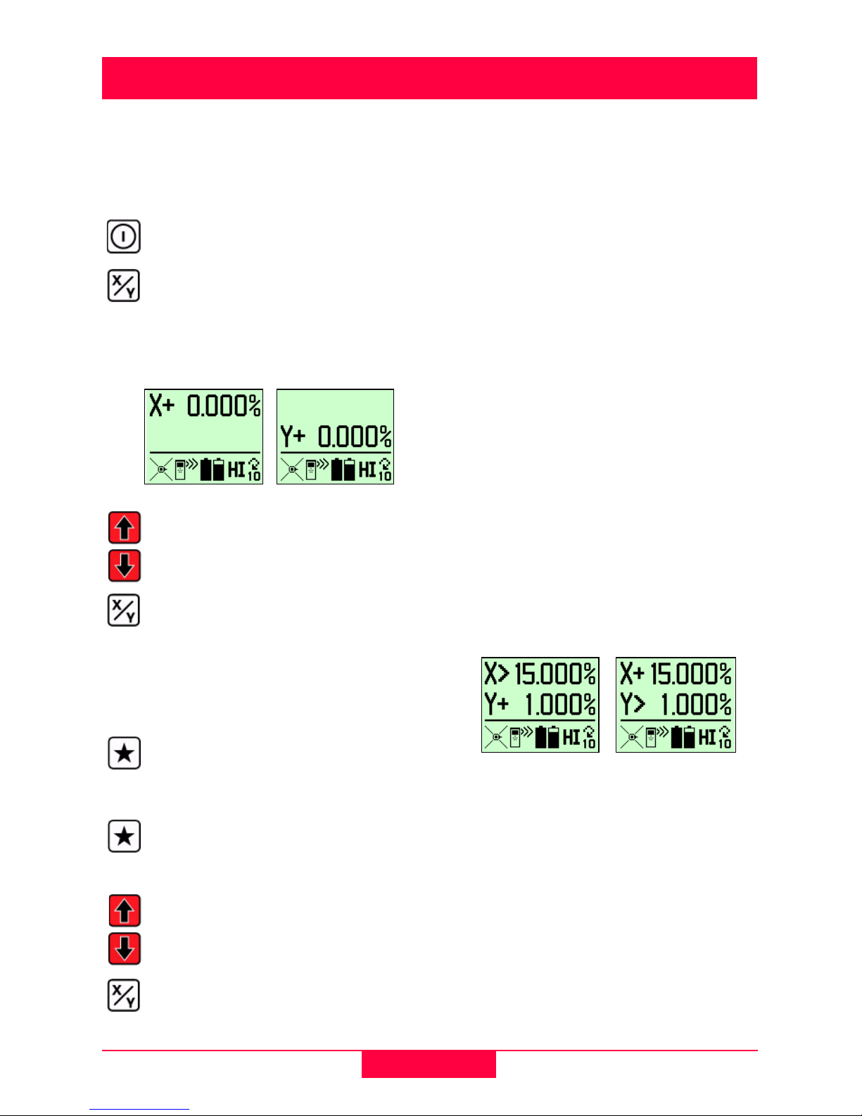
Entering Grade .............................. 6
Direct Grade Entry....................... 6
Grade Entry by Digit .................... 6
Grade Zero .................................. 6
Grade Capability.......................... 6
Grade Swap................................. 7
Grade Matching ........................... 7
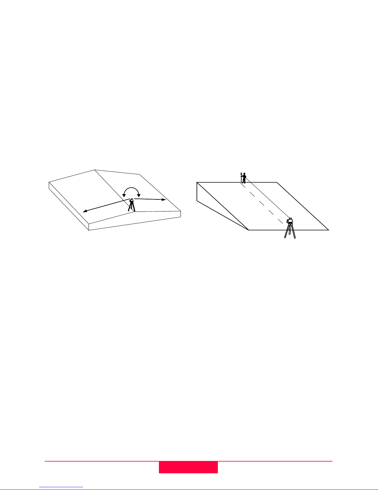
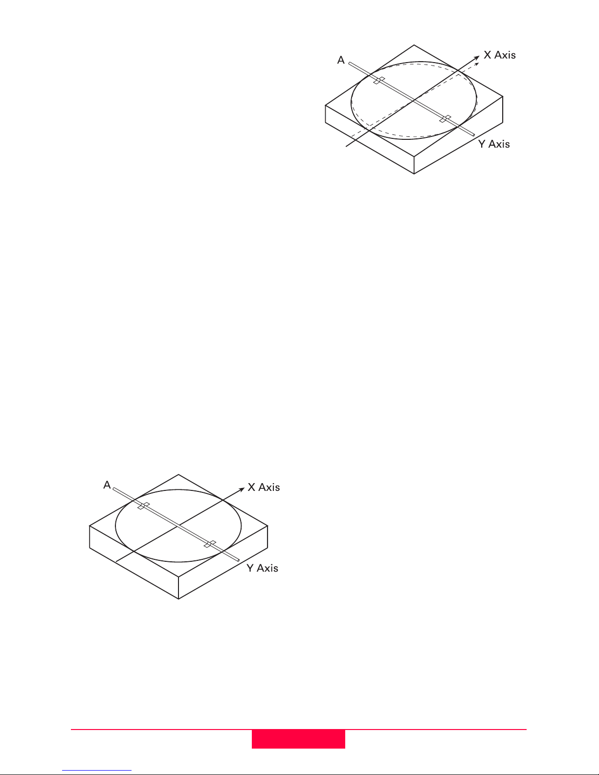
Identification of the Axes................ 8
Slope - Percent of Grade............... 8
Alignment of the Axes.................... 8
Precise Alignment of the Axes....... 9
Setup............................................ 10
General Setup.............................. 10
Location ..................................... 10
Recommended Head Speeds ... 10
Tripod Setup .............................. 10
Setup Options.............................. 11
Head Speeds............................. 12
H.I. (Height of Instrument) ......... 12
Automatic and Manual Mode:.... 12
Manual Mode with Grade .......... 12
Wind Sensitivity ......................... 13
Beam Masking........................... 13
Additional Setup Options ............. 14
Checking Level Accuracy....... 15
Checking Level Accuracy ............ 15
Checking the X-Axis .................. 15
Checking the Y-Axis .................. 15
Adjusting Level Accuracy............. 16
To Enter Adjustment Mode........ 16
X-Axis Accuracy Adjustment ..... 16
Y-Axis Accuracy Adjustment ..... 16
Accessories ............................... 17
Batteries....................................... 17
The Sighting Scope ..................... 18
Remote Control............................ 18
Troubleshooting........................ 21
Display Screen Explanations....... 21
Troubleshooting Suggestions ...... 22
Care and Transport .................. 23
Transport ..................................... 23
Storage ........................................ 23
Cleaning and Drying .................... 24
Safety Directions ...................... 25
General........................................ 25
Intended Use ............................... 25
Permitted use ............................ 25
Adverse use............................... 25
Limits of Use................................ 26
Responsibilities............................ 26
Warranty ...................................... 26
Hazards of Use............................ 26
Laser classification ...................... 29
Labeling ....................................... 29
Electromagnetic Compatibility
(EMC) .......................................... 30
Description................................. 30
Labeling Rugby 400 DG and
Remote Control ........................... 31
Technical Data........................... 32

4Introduction
Rugby 400 DG 1.1.0en
Introduction
The Rugby Grade laser is designed to
serve your needs in a wide variety of
applications.
It is a proven tool for increased
production with substantial reduction
of labor, time and material costs. It can
be used to accurately control land
leveling, sloped or level grading,
trenching, open cut mining, dredging,
contouring of levees, general
construction and excavation.
This manual contains operating and
set-up procedures for common
applications. Its purpose is to describe
the features of the Rugby and how the
Rugby operates. The manual is not
intended to describe specific
applications. Contact your local dealer
or Leica Geosystems for information
specific to your jobsite requirements.
The Rugby Grade lasers are rugged,
accurate and fully electronic with an
operating range up to 2,500 feet (770
meters) diameter.
The Rugby 400DG is a dual grade
laser and is capable of producing an
accurate plane of laser light for
applications that are level (1), single
grade (2), or dual grade (3).
Alignment is as easy as sighting over
the top of the Rugby to your control
point using the integrated alignment
sights or the optional sighting scope
assembly. For increased accuracy,
follow the procedure for Precise
Alignment of the Axes.

5Rugby 400 DG 1.1.0en
Features and Functions
1POWER Button – Powers the
Rugby on and off.
2LCD Display – Shows the grade
settings for the X and Y axes. The
display shows also Beam Masking,
Remote status, Battery status, H.I.
and Head Speed.
3X/Y Button – Press to set grade in
the X and Y-axis.
4UP Arrow Button – After pressing
X/Y, press to increase the grade
shown.
5STAR Button – Press to enter
setup screens and the grade entry
by digit screen.
6DOWN Arrow Button – After
pressing X/Y, press to decrease the
grade shown.
7Circular Level Vial – For initial
setup reference.
812-volt input – Charge the
batteries or run the Rugby directly
from 12-volts.
9Dual Batteries – The Rugby will
run with one or two sets of batteries
for maximum flexibility and battery
life.
10 Raised alignment sights and
mounting plate for the optional
sighting scope.
11 Easy grip handle for carrying and
setup.
12 Tripod mount for attachment to a
5/8”-11 tripod.

6Operation
Rugby 400 DG 1.1.0en
Operation
Entering Grade
Direct Grade Entry
Grade Entry by Digit
Grade Zero
The grade in either axis can quickly be
set to zero by pressing both the Up
and Down buttons simultaneously
while in either grade entry mode.
When changing grade using the direct
entry method, the counter will always
stop at zero. Release the button and
press again to continue counting
beyond zero.
Grade Capability
The Rugby 400DG can have up to
15% grade simultaneously in both
axes, or up to 25% in one axis.
Grades above 15% in one axis require
that the cross axis grade be ±1% or
lower. In this situation, if attempting to
enter grades greater than 1% or 15%,
a notice will appear on the screen
when the button is pressed.
)If no button is pressed, the
display will revert to the main display
after ten seconds.
Press POWER to turn the
Rugby on.
Press X/Y once to enter X-
axis grade. Press X/Y again to
enter Y-axis grade.The
display will show the grade
entry screens.
Use the UP or DOWN buttons
to set the desired grade.
Press X/Y to exit.
While in the grade entry
screens, press the STAR
button and a cursor will
appear on the +/- sign.
Press the STAR button to
move the cursor to the right.
Press the UP or DOWN
buttons to change the sign or
the digit that is highlighted.
Press X/Y to exit.

7Rugby 400 DG 1.1.0en
Operation
Grade Swap
The grade in the X and Y axes can
easily be swapped from positive to
negative in the Grade Entry by Digit
screen.
A typical application for this feature is
road building. For example, with the
Rugby setup on the crown of the road
and with one axis aligned to the center
line, the cross axis grade can be made
to fall to the right or lefthand side
simply by changing the +/- sign on the
display.
Grade Matching
In Direct Grade Entry mode the
movement of the leveling mechanism
moves at the same speed as the grade
counters.
To match an existing slope, set up the
laser over the known gradebreak
(base) of the slope, and align the laser
to the end of the slope with both control
points parallel to the direction of grade.
Adjust the Rod-Eye receiver on your
grade rod for the elevation of the laser
at the gradebreak next to the laser.
Move the grade rod to a point on the
slope that is too be matched. Then,
dial grade into the laser until the Rod-
Eye indicates an on-grade reading.
The percent of grade in the display is
now equal to the grade being matched.

8Operation
Rugby 400 DG 1.1.0en
Identification of the Axes
1X+ Axis – When positive grade is
entered in the X-axis, grade will
increase in this direction.
2Y+ Axis – When positive grade is
entered in the Y-axis, grade will
increase in this direction.
3Front of Rugby – See also axis
labeling on the sides of the laser
and inside the top windows.
Slope - Percent of Grade
Slope:
The change in elevation per unit of
measure (foot, meter, etc.)
Percent of Grade:
The change in elevation per 100 units
of measure (feet, meters, etc.)
Calculating Percent of Grade from
the Slope:
Slope = 0.0059
Conversion = 0.0059 x 100
Percent of Grade = 0.590%
Alignment of the Axes
When the desired grade is correctly set
in the display, it is necessary to align
the X and Y axes to the jobsite.
Ensure the circular level vial is
positioned near the center of the circle
for maximum self-leveling capability.
Ensure the Rugby is properly
positioned over a control point.
As shown, the direction of the X-axis is
seen from the front of the Rugby,
sighting over the top of the Rugby.
Rotate the Rugby slightly until the
sights are aligned with your second
control point.
Once aligned, work can begin.
)An optional sighting scope is
also available.
)For very accurate alignment,
refer to the steps for Precise Alignment
of the Axes.

9Rugby 400 DG 1.1.0en
Operation
Precise Alignment of the Axes
Under most conditions, the raised
alignment marks on the top of the
Rugby are adequate for alignment of
the axes. However, for more precise
alignment, use the following
procedure.
Objective:
• To establish Point A on the Y-axis
as a reference and take an
elevation reading.
• To dial grade into the X-axis and
then adjust the position of the laser
until the original elevation at Point A
is again found.
Procedure:
1 With 0.000% grade in both axes,
set up the Rugby directly over a
grade stake and rough align the Y-
axis to a second grade stake that
we will call Point A.
2 Take an elevation reading at Point
A using a Rod-Eye Receiver and a
survey rod.
3 Enter +5.000% grade into the X-
axis. When grade is entered in the
X-axis, the Y-axis acts like a hinge
or fulcrum.
4 With 5.000% in the X-axis, take a
second reading at Point A.
Alignment:
• If the second reading is equal to the
first reading, the X-axis is aligned
correctly.
• If the second reading is greater
than the first reading, rotate the
Rugby clockwise (to the right) until
the two readings are the same.
• If the second reading is less than
the first reading, rotate the Rugby
counter-clockwise (to the left) until
the two readings are the same.

10 Setup
Rugby 400 DG 1.1.0en
Setup
General Setup
Location
Make sure the location is clear of
possible obstructions that may block or
reflect the laser beam.
Make the most efficient use of the
Rugby’s operating radius. The Rugby
can be placed in the center of the
working area or to one side.
Make sure the ground is stable.
Ground vibration and extremely windy
conditions can affect the operation of
the Rugby.
If working in very dusty conditions,
place the Rugby up-wind. The dirt and
will then be blown away from the
Rugby and reduce interference.
Recommended Head Speeds
For surveying and manual machine
control applications the typical head
speed is 10 rps (600 rpm).
For automatic machine control
applications it is recommended to use
the highest head speed, 20 rps, to
increase the frequency of updates.
When working at extended distances,
decreasing the head speed
(increasing the pulse time on the
receiver) or changing the band width of
the receiver to wide band can improve
distance and performance.
Tripod Setup
Attach the Rugby securely to a tripod
or laser trailer, or mount on a stable
level surface.
Always check the tripod or trailer
before beginning work.
Make sure all screws, bolts, and nuts
are tight.
If your tripod has chains, they should
be slightly loose to allow for thermal
expansion during the day.
On extremely windy days, secure the
tripod. Placing a sandbag on each leg
can do this. (See also adjustment for
setting the wind sensitivity of the
Rugby.)
If using a tripod with a quick disconnect
adapter, point the control lever into the
wind. This places the locking
mechanism also into the wind, and will
provide better stability.

11 Rugby 400 DG 1.1.0en
Setup
Setup Options
The Rugby has several setup options
that are easily accessed and changed
in the first setup screen.
Changing the Setup Options:
When entering the setup screen, the
the EXIT window will be highlighted.
To change the setup options in this
window the buttons are used in the
following way:
Press the Star button and the cursor
will become a thick border around the
selected parameter. Once selected,
use the Up and Down buttons to
change the parameter.
)If no button is pressed, the
display will revert to the main display
after ten seconds.
From the main operating
screen, Press STAR to
access the setup screen.
Head Speed Selections –
5, 10, 15, 20 rps.
HI Function – Turns the H.I.
function on and off.
Automatic, Manual or Manual
with Grade.
Wind Sensitivity (1-5) – (1) for
calm days, (3) for normal
days, (5) for extremely windy
days.
Beam Masking – Turns the
beam off in the selected
quadrants.
Use the STAR button to select
or deselect the setup parame-
ters and exit the setup screen.
Use the UP and DOWN
buttons to move the cursor or
change the selected para-
meter.
Beam masking requires
using also the X/Y button.
With the beam masking option
selected, press the X/Y button
to turn the beam on or off in
the selected quadrant.
Use the Up and Down buttons
to move around the
quadrants.
The quadrant will become
solid and dark when selected
for the beam to be masked
(off) in the quadrant.
Select the EXIT window, then
press the Star button to exit
and return to the main display.

12 Setup
Rugby 400 DG 1.1.0en
Head Speeds
The Rugby can be set to any of four
different head speeds – 5, 10 , 15, or
20 rps. (300, 600, 900, 1200 rpm)
Select the head speed that provides
the best performance for your
application.
H.I. (Height of Instrument)
The H.I. function is used to prevent
elevation changes caused by
movement of the tripod.
When the H.I. Alert function is
activated, the self-leveling accuracy
remains the same, but the self-leveling
range of the Rugby is reduced.
Movement of the Rugby beyond its
self-leveling range will cause an “alert
condition”. The Rugby will stop rotating
and the following screen will appear on
the display:
Stop the “alert condition” by pressing
the Star or Power button and reset the
function.
Check carefully the setup and
elevation of the unit to determine what
has caused the alert condition. Adjust
as required to the correct elevation.
The H.I. function can be turned on or
off in the first setup screen.
When the H.I. function is turned on, the
letters “HI” will appear in the bottom,
right part of the display.
The H.I. function becomes active 30
seconds after the unit has completely
leveled and the head starts rotating.
Automatic and Manual Mode:
The Rugby will always turn on in
automatic mode and will continuously
self-level to maintain grade accuracy.
)In manual mode the self-
leveling function is turned off.
The display screen will show the
following:
The plane of laser light can be
changed using the X/Y and arrow
buttons, but the amount of change is
not shown in the display.
Manual Mode with Grade
In Manual Mode with Grade, the
display will alternately show the grade
entered for the X and Y axes.
The H.I. function can be
made to turn on automa-
tically at power-up. This
can be enabled in the
second setup screen.

13 Rugby 400 DG 1.1.0en
Setup
In this mode, grade can be entered into
either axis. The Rugby will self-level to
the grade input in the unit, then will
lock into manual mode at this grade.
)Once locked in manual mode
the self-leveling function is turned off.
If it is desired to change the manual
grade shown, a new grade can be
entered (same as in automatic mode)
and the Rugby will level to this new
grade, then lock in manual mode.
Wind Sensitivity
The Wind Sensitivity setting allows the
Rugby to operate in adverse
environmental and windy conditions,
while still ensuring maximum
accuracy.
Beam Masking
Electronic Beam Masking allows the
operator to turn off the laser beam in
specific quadrants to prevent
interference with other operations on
the job.
Using the setup menu, the beam can
be turned off in up to three selected
quadrants.
When a quadrant is turned off, the
space will appear dark.
The sensitivity numbers
can be set from 1 to 5.
Select “1” for calm
conditions. Select “5” for
very windy conditions.
Use the lowest setting
for conditions present.
The quadrants selected
can be either diagonals
of corners of the Rugby.
This selection is made in
the second setup
screen.
The settings for beam
masking are normally
not saved when the
Rugby is turned off. The
Rugby can be made to
save the mask settings
in the second setup
screen.

14 Setup
Rugby 400 DG 1.1.0en
Additional Setup Options
Additional setup options may be
accessed in a second setup screen.
Changing the Setup Options:
When entering the setup screen, the
EXIT window be highlighted.
To change the setup options in this
window the buttons are used in the
following way:
Press the STAR button and the cursor
will become a thick border around the
selected parameter. Once selected,
use the UP and DOWN buttons to
change the parameter.
)If no button is pressed, the
display will revert to the main display
after ten seconds.
+From the main
operating screen,
Press and hold the UP
button, then press the
STAR button to access
the second level setup
screen.
Selects beam masking
at the diagonals or at the
corners.
Allows the Rugby to
always start up with no
beam masking, or to
save and start up with
the last beam mask
setting used.
Allows the Rugby to start
up with the H.I. Alert
automatically turned on,
or turned off.
Allows the operator to
disable the negative
grade function of the
Rugby. When disabled,
negative grade cannot
be entered in the grade
displays.
The remote control is
enabled only when a
remote is to be used with
the Rugby. It is normally
off to conserve battery
power.
The STAR button is used to
select or deselect the setup
parameters.
The UP and DOWN buttons
are used to move the cursor
and change the parameters.
Select the EXIT window, then
press the STAR button to exit
and return to the main display.

15 Rugby 400 DG 1.1.0en
Checking Level Accuracy
)It is the responsibility of the user
to follow operating instructions, and to
periodically check the accuracy of the
instrument and work as it progresses.
)The Rugby is adjusted to the
defined accuracy specification at the
factory. It is recommended to check
your laser for accuracy upon receipt
and periodically thereafter to ensure
accuracy is maintained. If your laser
requires adjustment, contact your
nearest authorized service center or
adjust the laser using the following
procedure.
)Do not enter this mode or
attempt adjustment unless you plan to
change the accuracy. Accuracy
adjustment should be performed only
by a qualified individual that
understands basic adjustment
principles.
Checking Level Accuracy
To check level accuracy of your
Rugby, place the unit on a flat, level
surface or tripod approximately 100
feet (30 meters) from a wall.
Checking the X-Axis
Align the X-axis so that it is square to
the wall. Allow the unit to self-level
completely (approximately one minute
after the unit begins to rotate), and
then, using your Rod-Eye receiver,
mark the position of the beam
(Position 1).
Rotate the Rugby 180°, allow it to self-
level and then mark the opposite side
of the X-axis (Position 2).
Mark the position half-way between
the two marks. The X-axis is within its
accuracy specification if the two marks
are within ± 1/16” (± 1.6 mm) from
center.
Checking the Y-Axis
Align the Y-axis by rotating the Rugby
90° so that the Y-axis is now square to
the wall. Allow the unit to self-level
completely, then check the Y-axis in
the same way as above.
1
2

16 Checking Level Accuracy
Rugby 400 DG 1.1.0en
Adjusting Level Accuracy
To Enter Adjustment Mode
With the unit turned off, press and hold
both the Up and Down buttons, then
press the Power button to put the unit
in adjustment mode.
X-Axis Accuracy Adjustment
If entered correctly, the X-axis
adjustment screen will appear.
When entering the adjustment screen,
a small hour glass will appear. Wait
until the hour glass disappears before
checking and changing the adjustment
numbers.
Use the Up and Down arrows to
change the number and move the
beam to the half-way point between
the positions marked for the X-Axis.
Five counts in the display is equal to
approximately 1/16” at 100 feet (1.6
mm at 30 meters).
Press the Star button to accept this
position and accept the number in the
display for the X-Axis.
Press the Star button again to move to
the Y-Axis adjustment screen.
Y-Axis Accuracy Adjustment
If entered correctly, the Y-axis
adjustment screen will appear.
Wait until the hour glass disappears
before checking and changing the
adjustment numbers.
Use the Up and Down arrows to
change the number and move the
beam to the half-way point between
the positions marked for the Y-Axis.
Press the Star button to accept this
position and accept the number in the
display for the Y-Axis.
Press the Star button again to accept,
save, store the adjustment activity, and
to return to the main display screen.
)After adjustment, always check
your work.
)Always check accuracy prior to
critical applications. Repeated
activation of the grade mechanism
may result in accuracy variations up to
± 20 arc seconds.
)Pressing the power button at
any time before completing the
procedure will revert the accuracy to
previously saved information.

17 Rugby 400 DG 1.1.0en
Accessories
Accessories
Batteries
The unique battery solution in the
Rugby has two independent battery
compartments that will accept various
combinations of NiMH packs or
individual D-cell batteries (2).
The battery status is displayed on
power-up and as small icons on the
main operating screen.
Install the NiMH batteries (1) as shown
on the label of the pack.
Install individual D-cell batteries (2) as
shown on the battery door cover.
The charge jack (3) is located on the
laser above the locking knob of the
battery door (4).
Charge time is approximately 4-5
hours.
The Rugby can also be run directly
from a 12-volt source through the
charge jack.

18 Accessories
Rugby 400 DG 1.1.0en
The Sighting Scope
A sighting scope (739870) is
available as an optional accessory for
alignment of the axes and second day
setups.
The scope is magnetically mounted to
the top of the housing and once
aligned has a repeatable accuracy of
approximately ± 0.2°.
Alignment of the crosshairs
If using the scope for reference or
second day setup, use the raised
sights on the top of the laser to align
your Rugby to a second control point.
The scope is roughly aligned at the
factory. If a more precise alignment is
desired, first align the Rugby to a
second control point using the
procedure for Precise Alignment of the
Axes found in this manual.
A = Vertical crosshair alignment
Remote Control
The Rugby 400 DG Remote Control
(739854) is a full functioning, two-
way remote control.
The LCD display and the grade and
star buttons on the remote are the
same as on the Rugby.
The Power button turns on only
the remote. When pressed it will
communicate with the Rugby to
receive current information.
Once communication is established,
the remote can be used to change
grade and setup parameters on the
laser.
If the remote is not within range or
otherwise loses communication, the
the lost communication screen will be
displayed.
It is important, to achieve specified
distances, that the remote be used
within the “line of sight” of the Rugby.
Press and hold the power button for
1.5 seconds to turn the remote off.
A

19 Rugby 400 DG 1.1.0en
Accessories
The Standby button will cause
the Rugby to go into standby
mode for up to 16 hours. After
this time the Rugby will shut off and
can only be turned on again at the
laser.
When in standby mode the display will
show only a sleeping Rugby.
Pressing any button (except power)
while the unit is in standby mode will
cause the laser to return to normal
operation.
Automatic Shut Off - To conserve
battery power, the remote will
automatically shut off after two minutes
of non-use.
Low Battery – The remote will display
a low battery screen when the
batteries have reached a voltage
where the remote can no longer
communicate with the laser.
To replace the batteries, remove the
bottom cover of the housing. Install as
indicated on the side of the housing.
Before you can use the remote it is
necessary to enable the remote
capability on the laser.
To do this follow the instructions for
entering and changing the setup in the
second setup screen (page 14).
When enabled, the remote symbol will
appear on the bottom of the main
display.
Programing the remote – To program
the remote for your laser press and
hold the STAR button, then press the
POWER button.
The remote will search the immediate
area for Rugby units with remote
capability, and will identify these in the
display.
To select your laser highlight the serial
number and press the STAR button.
The remote will connect to the selected
laser.
To exit this screen without changing
settings, highlight EXIT - NO CHANGE
and press the X/Y button.
Change the remote
symbol in the setup
screen so that it no
longer has a line through
it.

20 Accessories
Rugby 400 DG 1.1.0en
Remote Notes
Setting the shut-off timer – The
remote is set from the factory to shut
off after two minutes of not being used.
To change this shut-off time, enter the
remote programming screen (just
described) by pressing and holding the
STAR button, then pressing the
POWER button.
When the Rugby select screen
is shown, press and hold the
STAND-BY button for 1.5
seconds. The shut-off time will change
between 120, 60, or 30 seconds each
time the button is held.
Backlighting – The LCD backlighting
is normally off to conserve battery
power.
To backlight the display on the
remote, press the power button
a second time after the remote
has been turned on.
Remote reception – The remote is an
RF (radio frequency) device with an
internal antenna. Always ensure that
the remote is within the “line of sight” of
the Rugby.
If the remote loses communication,
hold the remote at a different angle to
improve reception.
Table of contents
Other Leica Laser Level manuals

Leica
Leica Sprinter 150 User manual

Leica
Leica Wild t1010 User manual

Leica
Leica TPS1200 series User manual

Leica
Leica Lino ML90 User manual

Leica
Leica LINO L2P5G User manual

Leica
Leica Jogger 20 User manual

Leica
Leica Sprinter 50 User manual

Leica
Leica ML180 Series User manual

Leica
Leica Rugby 260SG User manual

Leica
Leica Lino L2 User manual

Leica
Leica TS12 Lite User manual

Leica
Leica NA720 User manual

Leica
Leica Rugby 820 User manual

Leica
Leica Rugby 880 User manual

Leica
Leica Lino L4P1 User manual

Leica
Leica LS10 User manual

Leica
Leica N3-70 User manual

Leica
Leica Rugby 410 User manual

Leica
Leica CS20 User manual

Leica
Leica Lino L4P1 User manual