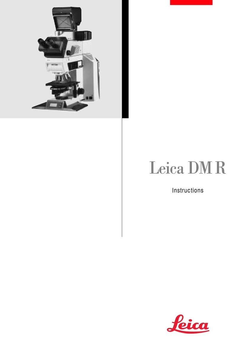
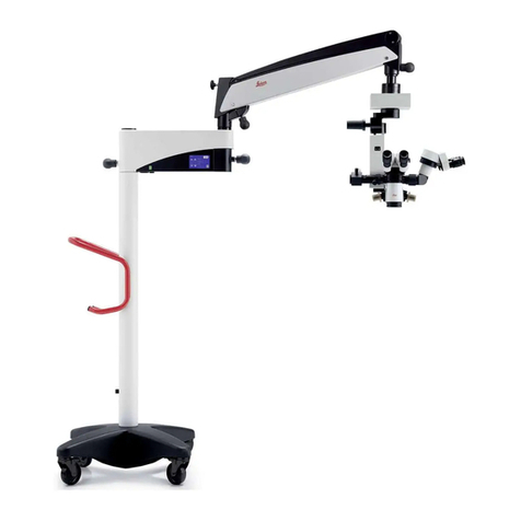
Leica DM2700 M User manual

Leica DM2700 M
Instructions · Bedienungsanleitung

2
Revision 1.2, published January, 21st 2013 by:
Revision 1.2, herausgegeben 21. Januar 2013 von:
Leica Microsystems CMS GmbH
Ernst Leitz-Straße 17-37
D-35578 Wetzlar (Germany)
http://www.leica-microsystems.com
Responsible for contents:
Verantwortlich für den Inhalt:
Marketing CMS

Leica DM2700 M
Instructions

4
Copyrights
Copyrights
All rights to this documentation are held by Leica
Microsystems CMS GmbH. Reproduction of
text or illustrations (in whole or in part) by print,
photocopy, microfilm or other method (including
electronic systems) is not allowed without ex-
press written permission from Leica Microsys-
tems CMS GmbH.
The instructions contained in the following docu-
mentation reflect state-of-the-art technology. We
have compiled the texts and illustrations as ac-
curately as possible. Still, we are always grateful
for comments and suggestions regarding poten-
tial mistakes within this documentation.
The information in this manual is subject to modi-
fication at any time and without notification.

5
Contents
Contents
1. Important Notes about this Manual ......... 7
1.1 Text Symbols, Pictograms and their
Meanings....................................................... 7
2. Intended Purpose of the Microscope....... 9
3. Safety Notes ............................................... 10
3.1 General Safety Notes................................ 10
3.2 Electrical Safety ......................................... 11
3.3 Transport and Storage............................... 12
3.4 Notes on Handling Light Sources............ 12
3.5 Notes on Handling Immersion Oil............ 12
3.6 Notes on Handling Acids and Bases...... 13
3.7 Disposal ...................................................... 13
3.8 Type Labels ................................................. 13
4. Overview of the Instrument ..................... 14
5. Unpacking the Microscope ..................... 19
6. Assembling the Microscope ................... 21
6.1 Stage .......................................................... 21
6.2 Condenser................................................... 23
6.3 Incident Light Axis ..................................... 24
6.4 Tube and Eyepieces................................... 24
6.5 Objectives.................................................... 24
6.6 Illumination.................................................. 25
6.6.1 LED Lamp Housing LH113................ 25
6.6.2 Lamp Housing 107/2*........................ 26
6.6.3 Lamp Housing 106z*......................... 27
6.7 Equipping the Incident Light Turret Disk 30
6.8 Analyzer and Polarizer.............................. 31
6.9 Lambda Plate Compensator*.................. 31
6.10 ICR/ICT Prisms............................................ 31
6.11 Optional Accessories ................................ 32
6.12 Connection to the Power Supply............. 34
7. Startup ......................................................... 35
7.1 Switching On............................................... 35
7.2 Köhler Illumination..................................... 35
7.2.1 Transmitted Light........................................ 35
7.2.2 Incident Light .............................................. 37
7.3 Checking Phase Contrast Rings .............. 38
7.4 Adjustment of Condenser Prisms............ 39
7.5 Adjusting the Light Sources
(106z Lamp Housing only) ......................... 41
8. Operation..................................................... 45
8.1 Switching On............................................... 45
8.2 Stages and Object Displacement............ 45
8.3 Focusing ...................................................... 46
8.4 Tubes48
8.5 Eyepieces .................................................... 49
8.6 Objectives.................................................... 50
8.7 Light Sources.............................................. 51
8.8 Aperture Diaphragm.................................. 51
8.9 Field Diaphragm (Transmitted Light)....... 53
9. Contrast Methods ...................................... 54
9.1 Incident Light .............................................. 54
9.1.1 Bright Field (RL)................................. 54
9.1.2 Oblique Illumination (RL).................. 54
9.1.3 Polarization (RL) ................................ 55
9.1.4 Interference Contrast ICR ............... 55
9.1.5 Dark Field (RL) ................................... 56
9.1.6 Fluorescence..................................... 56
9.2 Transmitted Light........................................ 57
9.2.1 Bright Field (TL)................................. 58
9.2.2 Phase Contrast (TL).......................... 59
9.2.3 Dark Field (TL).................................... 59
9.2.4 Oblique Illumination (TL).................. 60
9.2.5 Polarization (TL) ................................ 60
9.2.6 Differential Interference
Contrast ICT ....................................... 61
6
Contents
10. Measurements with the Microscope .... 63
10.1 Linear Measurements ............................... 63
10.2 Thickness Measurements ........................ 64
11. Trouble Shooting........................................ 65
12. Care of the Microscope............................ 69
12.1 Dust Cover................................................... 69
12.2 Cleaning....................................................... 69
12.3 Handling Acids and Bases ....................... 70
12.4 Changing Fuses .......................................... 70
13. Essential wear and spare parts .............. 71
14. Retrofitting Components........................... 72
14.1 Fitting the Filter Magazine
(Transmitted Light/Incident Light) .......... 72
14.2 Equipping the Condenser Disk................. 72
15. Index ............................................................ 75
16. EU Declaration of Conformity.................. 77

7
1. Important Notes about this Manual
(1.2)
→p.20
*
Numbers in parentheses, such as “(1.2)”, corre-
spond to illustrations (in the example, Figure 1,
Item 2).
Numbers with an arrow, e.g. → p.20, refer to a
specific page of the manual.
Explanatory note.
Item not contained in all configurations.
Notes on how to dispose on the microscope,
its components and expendables.
Caution!
Special safety instructions within this manual
are indicated with the triangle symbol shown
here, and have a gray background.
1.1 Text Symbols, Pictograms and their Mean-
ings
Caution!
This operating manual is an essential com-
ponent of the microscope, and must be read
carefully before the microscope is assem-
bled, put into operation or used.
1. Important Notes about this Manual
This operating manual contains important in-
structions and information for the operational
safety and maintenance of the microscope and
its accessories. It must therefore be kept safely
for future reference.

8
1. Important Notes about this Manual
!Caution! The microscope and accessories can
be damaged when operated incorrectly.
Danger due to hot surface.
Earth (Ground) terminal!
Caution - High voltage! Risk of electrical shock!!
China RoHS 10 years EFUP
(Environmentally friendly use period)

9
2. Intended Purpose of the Microscope
The Leica DM2700 M microscope with the ver-
sions Leica DM2700 M RL (for incident light ap-
plications) and DM2700 M RL/TL (for transmitted
light applications), to which this user manual
belongs, is designed for industrial, mineralogi-
cal and geological routine and research applica-
tions.
The microscope conforms to the Council Direc-
tives 2006/95/EC concerning electrical apparatus
and 2004/108/EC concerning electromagnetic
compatibility for use in an industrial environment.
Caution!
The manufacturer assumes no liability for
damage caused by, or any risks arising from
using the microscopes for other purposes
than those for which they are intended or not
using them within the specifications of Leica
Microsystems CMS GmbH.
In such cases the conformity declaration
shall cease to be valid.

10
3. Safety Notes
3. Safety Notes
3.1 General Safety Notes
This safety class 1 device is constructed and
tested in accordance with the harmonized
standards
EN 61010-1:2010
IEC 61010-1:2010
safety regulations for electrical measuring, con-
trol, and laboratory devices.
It also complies with EN 62471:2008 /
IEC 62471:2006, Photobiological safety of lamps
and lamp systems, and belongs to the exempt
level (no photobiological risk).
Caution!
In order to maintain this condition and to en-
sure safe operation, the user must follow the
instructions and warnings contained in this
operating manual.
Caution!
The instruments and accessories described
in this manual have been safety-tested and
checked for possible hazards.
Before modifying the instrument in any way
or combining it with non-Leica products not
dealt with in this manual, it is essential to
consult the Leica agency for your area or the
main factory in Wetzlar!
Any unauthorized interference with the in-
strument or use of the instrument for appli-
cations for which it is not designed will au-
tomatically cancel any warranty claim and
product liability!

11
3. Safety Notes
3.2 Electrical Safety
General specifications
For indoor use only.
Supply voltage:
Frequency:
Power input:
LED:
Fuse:
Ambient temperature:
Relative humidity:
Overvoltage category:
Pollution degree:
Caution!
The power plug may only be plugged into an
outlet equipped with a grounding contact.
Do not interfere with the grounding function
by using an extension cord without a ground
wire. Any interruption of the ground wire in-
side or outside of the device, or release of
the ground wire connection, can cause the
device to become hazardous. Intentional
ground interruption is not permitted!
Caution!
Through activating to the grounding connec-
tion (earth screw on the back of the micro-
scope) ancillary equipment with its own and/
or extra power supply may be brought to the
same ground wire potential. For connections
without a ground connector, Leica Service
must be consulted.
100-240 V AC
50/60 Hz
max. 80 VA
max. 15 W
T 1.6 A 250 V AC
15-35°C
max. 80% up to 30°C
(non-condensing)
II
2
Caution!
Never use any fuses as replacements other
than those of the types and the current rat-
ings listed here. Bridging the fuse holder is
not permitted. The use of incorrect fuses may
result in a fire hazard.
Caution!
The microscope’s electrical accessory com-
ponents are not protected against water. Wa-
ter can cause electric shock.
Caution!
Protect the microscope from excessive tem-
perature fluctuations. Such fluctuations can
lead to the accumulation of condensation,
which can damage the electrical and optical
components.
Ambient temperature: 15-35°C.
Caution!
Before exchanging the fuses or lamps, be
absolutely certain to switch-off the main
power switch and remove the power cable.
Caution!
Only use original power cord, or alternate
VDE- / HAR-certified power cords which
meet the minimum requirements of 3x0,75mm2
and 10A/250V.

12
3. Safety Notes
Caution!
Per definition, the connection between
power supply cable and appliance inlet is
the power separator of this device. Thus, the
user is responsible for sufficient clearance
and accessibility of this area at all times.
Caution!
Do not use the microscope in altitudes ex-
ceeding 2000 m ASL/NL.
3.3 Transport and Storage
Caution!
Fully equipped, the microscope weighs more
than 18 kg. For transportation, the user has to
take care of the corresponding actions.
See also p. 20.
Caution!
Transport and storage in a range of -25°C –
+70°C and at a humidity not exceeding 80%
(non-condensing).
3.4 Notes on Handling Light Sources
Caution!
Light sources pose a potential irradiation risk
(glare, UV radiation, IR radiation). Therefore,
lamps have to be operated in closed housings
and only after being mounted.
Never look directly into the beam path (blind-
ing hazard).
Caution!
Lamps and lamp housings may be hot!
They must be placed at least 10 cm away
from the wall and away from flammable sub-
stances.
Particulary, supply and data lines must not
encounter lamp housings!
3.5 Notes on Handling Immersion Oil
Caution!
When using immersion oil, take care to avoid
skin contact! Ask the supplier for a safety
data sheet!

13
3. Safety Notes
3.6 Notes on Handling Acids and Bases
For examinations using acids or other aggressive
chemicals, particular caution must be taken.
Caution!
Be absolutely certain to avoid direct contact
with these chemicals.
3.7 Disposal
After the end of the product’s life, please contact
Leica Service or Leica Sales on how to dispose
of it.
Please observe the national laws and ordinances
which, for example, implement and ensure com-
pliance with EU directive WEEE.
Note!
Like all electronic instruments, the micro-
scope, its components and expend-ables
may not be disposed of as general household
waste!
3.8 Type Labels

14
4. Overview of the Instrument
Specification
Contrast Method
Incident Light Axis
with 4x Filter Turret Disc
Transmitted Light Axis
Illumination
Tube
Leica DM2700 M
• Incident Light: Brightfield, Darkfield, Polarization
Differential Interference Contrast,
Fluorescence, Oblique Illumination
• Transmitted Light: Brightfield, Darkfield, Phase Contrast,
Polarization, Differential Interference Contrast
Incident-light illuminator for up to eyepiece field number 22
with
• 4x filter turret disc (BF, DF, POL, IRC, FLUO, OBL)
• 2 filter positions, selectable
• Color-coded centerable aperture
• Pre-centered field diaphragm
• Manual brightness adjustment
Manual adjustment of
• Light intensity
• Aperture diaphragm
• Field diaphragm
• Toggle switch for TL/RL
• LED lamp housing LH113
• Optional: external light sources
• Lamp housing 107/2
• Lamp housing 106z
• Leica EL6000
• Leica SFL100/4000/7000
Optionally with
• Fixed or variable viewing angle
• Up to 3 switching positions
• One or two camera ports
• Ergotube with height-adjustable eye level and camera port
• With upright image

15
4. Overview of the Instrument
Specification
Magnification Changer
(optional)
Objective Turret
XY Stage
Condenser
Focusing
Leica DM2700 M
• Manual
• Magnifi
cation steps: 1x; 1.5x; 2x
• Manual
• 6x or 7x for objectives with M25 thread
• 5x for objectives with M32 thread
• Objective prism slide
• With condenser holder
• Coaxial pinion, optional: telescoping stage controls
• Controls mountable on left or right
• Condenser CL/PH 0.90/1.25 OIL with color coding
(the diffusion filter slide is required with objectives < 10x)
• Condenser CLP/PH 0.85 for polarization
(the diffusion filter slide is required objectives < 10x)
• Condenser Achr. Apl. A 0.9 (P) with color coding and condenser
head that can be pivoted in and out
• Universal condenser UCL 0.90/1.25 OIL (UCLP 0.85 for polarization
with 5-position light ring disk)
(the adapter lens (diffusion filter) is requiredwith objectives < 10x)
• Pol universal condenser UCL/P with interchangeable condenser
head and 6-position condenser disk
• Focus dial for coarse and fine adjustment
• Height adjustment
• Speed Switch (optional)
• Adjustable focus threshold and movement rate

16
4. Overview of the Instrument
Fig. 1 Left side of the microscope Leica DM2700 M
1LED lamp housing LH113
2Coarse and fine focusing
3Intensity adjustment
4Condenser height adjustment
5Field diaphragm adjustment
6On/off switch
7Polarizer
8Coaxial pinion for x/y stage movement
9Aperture diaphragm
10 Condenser
2356
14
12
13
11
10
9
8
74
15
16
17
11 Specimen stage with specimen holder
12 Objective turret with objectives
13 Objective prism slide
14 Tube
15 Eyepiece tube
16 Eyepieces
17 Analyser
18 Centering keys for aperture diaphragm
19 Aperture diaphragm centering
20 Transmitted light/incident light switch
(DM2700 M RL/TL only)
20
1
18
19

17
4. Overview of the Instrument
Fig. 2 Right side of the microscope Leica DM2700 M
1Eyepieces
2Eyepiece tube
3Tube
4Objective prism slide
5Objective turret with objectives
6Specimen stage with specimen holder
7Condenser height adjustment
8Coarse and fine focusing
9Coaxial pinion for x/y stage movement
10 Incident-light axis
11 Color-coded aperture diaphragm and adjustment of ob-
lique illumination
12 Filters (2)
13 Filter turret
14 Polarizer
15 LED lamp housing LH113
1
2
3
4
5
6
7 8 9
10 11 12
13
14
15

18
4. Overview of the Instrument
410
496
330
115
Dimensions (specification in mm)

19
5. Unpacking the Microscope
Allowable ambient conditions:
Temperature 15–35°C
Relative humidity: max. 80% up to 30°C
non-condensing
Microscopes in warm and warm-damp climatic
zones require special care in order to prevent
fungus contamination.
See the chapter on „Care of the Microscope“ →
p. 69 for additional instructions.
Caution!
Electrical components must be assembled
at least 10 cm from the wall and away from
flammable substances.
Caution!
When installing the microscope, make sure
the power inlet is freely accessible so that
the instrument can be quickly disconnected
from the mains if necessary.
First, carefully remove all components from the
transportation and packaging materials.
Note:
If at all possible, avoid touching the lens surfaces
of the objectives. If fingerprints do appear on the
glass surfaces, remove them with a soft leather
or linen cloth. Even small traces of finger perspi-
ration can damage the surfaces in a short time.
See the chapter on „Care of the Microscope“ →
p. 69 for additional instructions.
Caution!
Do not connect the microscope and periph-
erals to the power supply at this point under
any circumstances!
Installation location
Work with the microscope should be performed
in a dust-free room, which is free of oil vapors
and other chemical vapors, as well as extreme
humidity. At the workstation, large temperature
fluctuations, direct sunlight and vibrations should
be avoided. These conditions can distort meas-
urements and micrographic images.

20
5. Unpacking the Microscope
Transport
For shipping or transporting the microscope and
its accessory components, the original packag-
ing should be used.
As a precaution to prevent damage from vibra-
tions, the following components should be disas-
sembled and packaged separately:
• Unscrew the objectives.
• Remove the incident light axis.
• Remove the condenser.
• Remove the coaxial pinion.
• Remove the lamp housings.
• If present, disassemble the burner in the 106z
lamp housing.
• Remove all moving or loose parts.
Weight
The weight of the microscope depends on the
particular equipment.
Fully equipped, the microscope weighs more
than 18 kg. For transportation, the user has to
take care of the corresponding actions.
Caution!
For transporting it is essential to remove all
components listed under “Transport”!
Table of contents
Languages:
Other Leica Microscope manuals

Leica
Leica EZ4 User manual

Leica
Leica MicroStar IV User manual

Leica
Leica TCS SP5 X User manual

Leica
Leica DM1000 LED User manual

Leica
Leica TCS SPE User manual

Leica
Leica DM LM Reference guide

Leica
Leica DM IRM User manual

Leica
Leica M165 FC User manual

Leica
Leica DM6000 M User manual

Leica
Leica DM750 M User manual