manuals.online logo
Brands
  1. Home
  2. •
  3. Brands
  4. •
  5. Leica
  6. •
  7. Microscope
  8. •
  9. Leica SP2 User manual

Leica SP2 User manual

Byeong Cha Page 1 11/24/2009




Manual for Leica SP2 Confocal Microscope
Enter you name, the date, the time, and the account number in the user log book.
Things to check before start-up.
•Make sure that your sample slides are clean and sealed. Use Windex and cotton balls or Kimwipes to clean
coverslips. Fixed samples need to be sealed with nail polish.
•Check the objectives. The 10x and 20x objectives are DRY objectives, and should NEVER have oil on them!
There are 40x and 63x OIL immersion objectives, and a 63x WATER immersion objective also on this
microscope. If oil immersion objectives have oil on them, wipe the lens gently only with lens paper. With
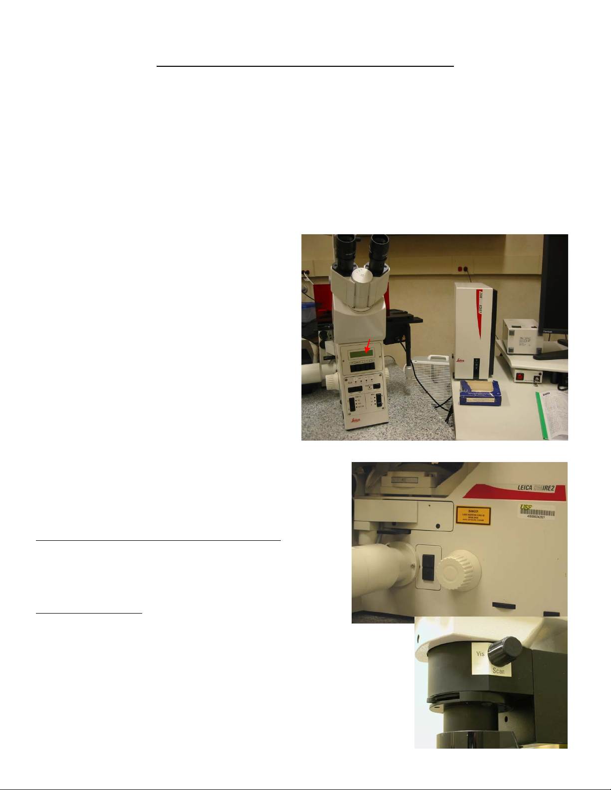
the microscope controllerON, you see the information of the objective in position on the reading panel
at the front of the microscope. The order of
the objective lenses in the lens turret is:10X, 20X,
40X Oil, 63X Oil, and 63X Water.
•The 63X objective has aperture collar adjustment
rings that control the size of aperture opening. It
should be wide open for most imaging condition.
If your sample looks dim or the whole view field
is not illuminated evenly when you look through
the eyepieces, turn the collar to open the aperture.
•The field diaphragm and aperture diaphragm in
the excitation path of the mercury lamp are
controlled by round, black dials on the left side
toward the back of the microscope, and control
the fluorescence illumination from the mercury
lamp. For all imaging with the mercury light
source, these should be set wide open by turning all the way counter-clockwise.
Setting up for bright-field and fluorescence
viewing.
Basic Operation of Leica DM IRE2 Microsocpe.
Turn on the microscope controller .
Turn on the mercury arc lamp.
Bright-field viewing:
Place your sample slide with coverslip (preferably #1.5
thickness) facing down to the objective on the stage.
For bright-field viewing, turn on the microscope light by turning the wheel
toward you and turn the VIS-SCAN switch to VIS position (Note:
switch back to Scan position for confocal scanning, see below)
Start with low magnification objectives (10X or 20X) first to find and focus
onto your specimen. The information of the selected objective and their z-



Byeong Cha Page 2 11/24/2009




1
 
position can be read on the readout panel at the front of the scope. You
can place the desired objective in position by turning the lens turret by
hand or by pressing the objective change button on the left side of the
microscope.
Pressing upper objective change button once rotates in next higher
objective into place and pressing lower change button rotates in next lower
objective into place.
However, pressing these buttons does not change between dry and oil
objectives. To do this, first press buttons  simultaneously,
and when the readout panel reads “change objective I (or D by
pressing again)”, then push the objective change button .
To focus, use coarse movement button (upper one for bring lens
up to a safety distance, “0” position and lower one for lowering
lens down) and fine focus knob (9) for focusing. The coarseness of
focusing movement (“S0” (fine) to “S3” (coarse)) can be set by
pressing “STEP” button.
For using oil or water immersion lens, lower the objective
turret slightly, expose the lens by turning the turret half
way, and place a drop of oil or water on the objective (be
careful not to touch the lens directly with application
tools!). Place the slide over the objective and raise the
objective until the oil just spreads out as it contacts the
slide. Use find focus knob to gradually bring your sample
into focus. Check your slide occasionally to make sure that
you are not pushing up the slide with the objective. This
can damage the objective lens and your sample!
Please DO NOT press “LEARN” and “CHANGE”
buttons.
Fluorescent viewing:
You can check your sample to see if your fluorescence labeling
works by using the mercury lamp illumination and the
appropriate filter set. The microscope has filter sets for viewing
DAPI (A), Green fluorescence (I3) and red fluorescence (N2.1).
Press the arrow horizontal button  on the front of the scope to
choose the filter set. “Scan” position has no filter set in place and
is used for laser confocal scanning. The fluorescent light can be
blocked (closed) or emitted by pressing Shutter  button. The
“closed” light should be off for fluorescent viewing.
Turn the VIS-SCAN switch to Scan position to block the
transmitted bright-field light, if necessary.

Byeong Cha Page 3 11/24/2009
Setting up for Confocal Imaging.
Turn on the Scanner/Laser He/Ne switch  (the
scanner should be on for about 1 min before starting
the LCS program).
Turn on the PC/Stand switch  and turn on the
computer. Log onto using your User ID and
password or TCS User.
Start the LCS program by double-
clicking the LCS icon.
On the main menu, select the Personal that contains your setting for acquisition parameters you have created or
Company for a default setting.
To start the laser(s);
(1) Turn on only the lasers you will use. They do not
need more than a minute or so to warm up and
stabilize, so it is not necessary to turn them on
until you know you need them.
(2) Argon (for 458, 476, 488, and 514 nm laser): Turn
on the red Laser Ar/ArKr switch  and turn the
Level Ar/ArKr knob  to MIN. Then, turn the
left Ar/ArKr key  to “ON”, then push to
“START” and release. Adjust the laser power with
LEVEL knob (usually 9 o’clock position is
sufficient).
(3) Melles Griot yellow DPSS (561 nm) laser: push
the green button .
(4) He/Ne (633 nm) laser: turn on the right He/Ne 633
key.
(5) Diode UV laser 405 nm: Turn on the red power button and turn the key  to Iposition.








Byeong Cha Page 4 11/24/2009
LCS Imaging program setting
Upon LCS program start, the basic image acquisition menu will appear. The “Acquire” button should appear
pressed.
Click “Beam” button and select the appropriate detector setup for the
fluorescent labels you used on your sample from the drop-down list .
This will set up the emission detector band-width, activate the proper
detector (PMTs), dichroic beamsplitter, and excitation laser wavelength
and power. You can adjust the range and position of detector bandwidth
and the laser power level as necessary. 
You also can change the color scheme of individual images into any color
or grey scale by clicking the pseudo-color selector  associated with
PMTs on the window screen (Note: the color information will be saved
with image files when saved).
Press Mode button to select Scan Mode (default is XYZ).
Press Format, Speed, and Bit buttons to select these parameters (defaults are 512x512 format, 400Hz scan
speed, and 8 bit image).
Detector
bandwidth
and range
Laser power level
Dichroic
beamsplitter
setting
Detector selector &
pseudo-color selector


Byeong Cha Page 5 11/24/2009
Press Z-scan button and select z-Wide in order to use Z POS knob to
move the objective for focusing (Default is z-Galvo, which is used with
Galvo stage adaptor).
Click MicCtrl button to switch to “Visual” mode, in which you can
examine your sample visually at the microscope. Switch “MicCtrl” to
“Scan”mode for laser scanning (it will automatically shut off visual
output through the eyepieces).
Press “Continuous” button to start scanning. An image or images, depending on the number of active
detectors, will appear on the right monitor.
Control Panel
Optimize the images by adjusting parameters including;
•The z-position (focusing) within the specimen (Z-POS knob).
•Zoom factor (ZOOM knob ): Default is 1. Increasing zoom will magnify the image but also will bleach
the sample faster!
•PMT and Smart Offset knobs : Turn PMT knobs to increase the signal intensity of each fluorescent and
transmission image channel. To decrease background signal, click the mouse over the image channel to
select it and turn Offset knob counterclockwise. By activating Q LUT button , a full dynamic range of the
PMT can be obtained. In this mode, pixels saturating the PMT will appear blue and pixels which are black (0
value) appear green. Set the PMT gain so that the brightest pixels are just under the saturation and set the
PMT offset such that the darkest pixels are just above the zero value.
•Laser power: adjust with dragging the laser power bar on the menu window if necessary.
Click the Continuous button again to stop scanning.
You can save the current parameter setting with Save button for later use.



Byeong Cha Page 6 11/24/2009
Working with Images.
Single button–
puts up full screen
of one fluorescent
channel.
Ch1, 2, 3, 4
buttons– activate
the channel on the
screen.
Tiled button–
views up to 3
channels
simultaneously.
Ovl button –
overlays (merge)
multiple channels
into one.
Lut button- open
color look up
table.
Acquiring Single Optical Section Image.
Make sure to switch ”MicCtrl” to Scan mode.
Press “Single Scan” button to acquire an image by a single laser scanning at a scanning speed (normally
400Hz). The resulting image may display background noise. Image averaging is a process to decrease this noise
and improve the signal-to-noise ratio.
To use averaging, click either “Aver”(frame averaging) or “Li.A”. (line averaging) button and select the
number of frames (or lines) to be averaged. Then, click “Single Scan”button.
Sequential Scanning Mode
This confocal microscopy can detect up to four fluorophores simultaneously as long as all the excitation and
emission spectra of fluorophores are well separated. Imaging of samples stained with different dyes thus simply
requires manipulation of laser power and adjustment of the detector bandwidth. However, often excitation of
one fluorophore may cause emission into the range of another (bleed-through) or can be induced by neighboring
laser lines (cross-talk), which produce false signals. To avoid these, the sample can be scanned sequentially by
collecting one fluorophore signal at any given time.
Byeong Cha Page 7 11/24/2009
To scan sequentially:
•Choose the beam setting parameter
for your fluorophores (i.e. GFP and
DsRED) by selecting laser lines,
dichroic mirror, and PMTs.
•Set up a condition for one fluorophore by only activating and adjusting laser level and PMTs. Save this
parameter set up as your own setting (i.e. “GFP-seq”) .
•Repeat the same process for the other fluorophore and save the condition as another setting (i.e. “DsRED-
seq”).
Byeong Cha Page 8 11/24/2009
•Click the Seq button in the beam window. Add the fluorophore acquisition setting one at a time by
selecting them in the beam window and then click Add button in the Sequential scan settings window.
Keep the scan mode at “between lines”
Do not close the settings window.
You can save these sequential
acquisition settings by Save  button.
•Start the acquisition by clicking Single
Scan or Series button depending on
your imaging condition.
Acquiring Z-series images.
Z-series allows obtaining optical sections through the certain volume of your sample that can be used for
making 3D images.
To set the z range, press “Continuous”button (it will be highlighted with “Stop”), turn Z-POS knob in a
direction to focus to a specific z position of your sample and click Begin button (it will appear depressed).
Turn Z-POS in opposite direction to reach a desired position and click End button .
Click Stop button to stop scanning.
Click Series button to check the thickness of the z-series and determine the number of optical sections.





Byeong Cha Page 9 11/24/2009
Click Sect button  to select the predetermined number of optical section, or to select Others …
It brings up a z-configuration window to determine the number of sections and spacing (step size) between
sections. Press OK.
Choose the number of averaging using “Aver”button and click “Series”button to begin Z-series stack
imaging.
Acquiring Time Series images.
Time series allows time-lapse
imaging of live samples to
study the changes and
dynamics of your object of
interest. The movie can be
saved as multiple Tiff files and
AVI files for playing in movie
programs.
To set obtain time-series images,
select scan Mode as xyt (or
other modes containing‘t’). It will
activate “Time” button .
Click “Time” button to open the
time-lapse setting dialogue and set
the parameters such as the time
interval between frames and the
number of frames. Hit Enter key
on keyboard, which will calculate
the complete time. Click “Apply”.
(Option) Click on Aver or Li.A. button to set the number of averaging per frame. Note: If your object of
interest changes or move faster than scanning speed, averaging will generate distorted or ghost images. To
increase the signal, use slower scan speed.
Click “Series” button to start the time series imaging.
Set time
interval
Set the number
of frames




Byeong Cha Page 10 11/24/2009
Saving Images.
This is a very important for your effort and data. Computer crash or power outage will result in loss of
unsaved data! SAVE FREQUENTLY!!
To save the imaging data files, click “Save” button at the top of the window. Select Ddrive and users folder.
Create your folder, rename the Experiment# and save.
Since the storage memory in the computer will be filled up quickly and this lack of hard drive space prevents
image acquisition, all user files will be deleted after two weeks. Be sure to copy your files to a flash memory or
CD/DVD disks.
Shut-down Procedure
Please enter your time of use in the log book and note any problems and suggestions during your time.
1. Clean the oil from the objectives only with lens paper (not Kimwipe). Clean the microscope and stage.
2. Close the LCS program.
3. Copy your data files to a flash drive or CD. Users are responsible for their own files, as there is no
automatic backup at present.
4. Log off the computer (not turning off the computer) and turn off the microscope control box.
5. If the next user won’t be ready within 1 hour: Turn off the mercury lamp.
6. If you are the last user of the day:
a. Turn off the mercury lamp.
b. Minimize the power of the Ar for >3min before turning it off.
c. For the Ar laser, turn the key to “off” and after 10 min turn off the red button switch.
d. Turn the Melles Griot DPSS laser off by pushing the OFF button.
e. For the He/Ne, turn the key to off position.
f. Exit windows and shut down the power for PC stand, Scanner/Laser HeNe, and Laser Ar/Kr with the
red buttons.

Other manuals for SP2

1

Other Leica Microscope manuals

Leica MATEO TL User manual

Leica

Leica MATEO TL User manual

Leica CME User manual

Leica

Leica CME User manual

Leica TCS SP5 X User manual

Leica

Leica TCS SP5 X User manual

Leica MC120 HD User manual

Leica

Leica MC120 HD User manual

Leica VOH IV User manual

Leica

Leica VOH IV User manual

Leica DM IRM User manual

Leica

Leica DM IRM User manual

Leica TCS SP8 MP User manual

Leica

Leica TCS SP8 MP User manual

Leica M620 F20 User manual

Leica

Leica M620 F20 User manual

Leica MATEO TL User manual

Leica

Leica MATEO TL User manual

Leica DM750 M User manual

Leica

Leica DM750 M User manual

Leica DMIL User manual

Leica

Leica DMIL User manual

Leica MacroFluo User manual

Leica

Leica MacroFluo User manual

Leica M125 C User manual

Leica

Leica M125 C User manual

Leica M165 FC User manual

Leica

Leica M165 FC User manual

Leica DM750 M User manual

Leica

Leica DM750 M User manual

Leica TCS SP5 X User manual

Leica

Leica TCS SP5 X User manual

Leica TCS SP8 User guide

Leica

Leica TCS SP8 User guide

Leica DM2700 M User manual

Leica

Leica DM2700 M User manual

Leica ATC 2000 User manual

Leica

Leica ATC 2000 User manual

Leica DMS300 User manual

Leica

Leica DMS300 User manual

Leica EZ4 User manual

Leica

Leica EZ4 User manual

Leica DM100 User manual

Leica

Leica DM100 User manual

Leica M500 OH3 User manual

Leica

Leica M500 OH3 User manual

Leica DVM5000 User guide

Leica

Leica DVM5000 User guide

Popular Microscope manuals by other brands

Accu-Scope MT-40 Series manual

Accu-Scope

Accu-Scope MT-40 Series manual

Olympus BHTU instructions

Olympus

Olympus BHTU instructions

JC LAB Bimc-12N1000 Operation manual

JC LAB

JC LAB Bimc-12N1000 Operation manual

Carson MicroFlip MP-250 quick start guide

Carson

Carson MicroFlip MP-250 quick start guide

Bresser 5702100 instruction manual

Bresser

Bresser 5702100 instruction manual

Nipon Optics x instruction manual

Nipon Optics

Nipon Optics x instruction manual

OCULUS BIOM 5c instruction manual

OCULUS

OCULUS BIOM 5c instruction manual

Celestron 44308-B instruction manual

Celestron

Celestron 44308-B instruction manual

LEITZ ortholux instruction manual

LEITZ

LEITZ ortholux instruction manual

My First Lab DUO SCOPE MFL-06 user manual

My First Lab

My First Lab DUO SCOPE MFL-06 user manual

Conrad 19 12 33 operating instructions

Conrad

Conrad 19 12 33 operating instructions

AmScope IN300 Series user manual

AmScope

AmScope IN300 Series user manual

HOZAN L-845 instruction manual

HOZAN

HOZAN L-845 instruction manual

KERN Optics OIV-6 User instructions

KERN Optics

KERN Optics OIV-6 User instructions

SCHOTT KL 2500 LCD Instructions for use

SCHOTT

SCHOTT KL 2500 LCD Instructions for use

3B SCIENTIFIC PHYSICS 500 1013146 instruction manual

3B SCIENTIFIC PHYSICS

3B SCIENTIFIC PHYSICS 500 1013146 instruction manual

Zeiss OPMI PROergo S7 Instructions for use

Zeiss

Zeiss OPMI PROergo S7 Instructions for use

Ken A Vision Digital Comprehensive Scope 2 instruction manual

Ken A Vision

Ken A Vision Digital Comprehensive Scope 2 instruction manual

manuals.online logo
manuals.online logoBrands
  • About & Mission
  • Contact us
  • Privacy Policy
  • Terms and Conditions

Copyright 2025 Manuals.Online. All Rights Reserved.