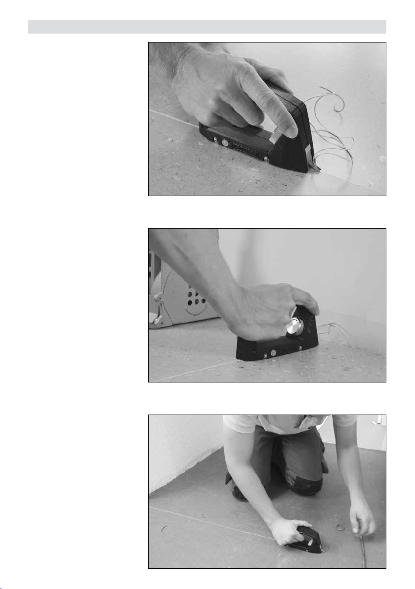
Leister GROOVY User manual

®GB IF
E
D
CN
TR RUS
Hand
grooving tool
GROOVY
Leister Technologies AG
Galileo-Strasse 10
CH-6056 Kaegiswil/Switzerland
Tel. +41 41 662 74 74
Fax +41 41 662 74 16
www.leister.com

GB
I
F
E
D
CN
TR
Deutsch Bedienungsanleitung 3
English Operating Instructions 9
Italiano Istruzioni per l‘uso 15
Français Notice d’utilisation 21
Español Instrucciones de funcionamiento 27
Türkçe Kullanım Kılavuzu 33
Русский Инструкция по эксплуатации 39
中文 使用手册 45
RUS

3
Bedienungsanleitung vor Inbetriebnahme aufmerksam
lesen und zur weiteren Verfügung aufbewahren.
Bedienungsanleitung (Original-Bedienungsanleitung) D
Handfugenhobel GROOVY vor Schmutz und Nässe schützen.
Handfugenhobel GROOVY
• Fugenvorbereitung ohne Fräsen
• Fugenhobel bis zum Wandabschluss
• Sauberer Übergang von maschinell gefräster Fuge zum Abschluss
• Ideal für kleine und schwer zugängliche Flächen
• Genaues Arbeiten dank Rollenführung und verstellbarer Fugentiefe
Warnung
Technische Daten
Fugenbreite 3.5 mm (0.14 inch) U-Form
Fugentiefe max. 3 mm
Material PVC und Linoleum
Technische Änderungen vorbehalten
Vorsicht
Anwendung
Der Handfugenhobel GROOVY darf nur mit der im Lieferumfang enthaltenen
Fugenklinge eingesetzt werden.
Verletzungsgefahr: Das Berühren der Fugenklinge des Handfugenhobel
GROOVY kann zu Schnittverletzungen führen.
Gerät darf nur von ausgebildeten Fachleuten oder unter deren Aufsicht benützt
werden. Kindern ist die Benützung gänzlich untersagt.

4
Gerätebeschreibung
Vorbereitung
1. Handgri
2. Schutzkappe
3. Fugenklinge
4. Einstellrad Fugentiefe
5. Ersatz-Schutzkappe
6. Klingenhalter
Schutzkappe (2) vorsichtig
entfernen.
ACHTUNG!
Die Fugenklinge (3) nicht be-
rühren. Dies kann zu Verletzun-
gen führen.
1
5
32
2
3
6
4

5
Einstellung Fugentiefe
Die Fugentiefe ist auf das zu
schweissende Material abzu-
stimmen.
Drehen des Einstellrades (4) im
Gegenuhrzeigersinn ergibt eine
tiefere Fuge (+), Drehen des Ein-
stellrades (4) im Uhrzeigersinn
ergibt eine weniger tiefe Fuge
(-). Eine Umdrehung ergibt eine
Tiefenänderung von ca. 0,35 mm.
Ist der Klingenhalter (6) bündig
mit dem Gehäuse, erreicht die
Klinge eine Schnitt-Tiefe von ca.
0,5mm.
Ist der Klingenhalter (6) ganz
ausgefahren und am Anschlag,
erreicht die Klinge eine maximale
Schnitt-Tiefe von ca. 3,0 mm.
4
6
6

6
Anwendung
Das Gerät wird mit Hilfe der inte-
grierten Führungsrollen in der be-
reits geschnittenen Fuge geführt.
Ausführen sauberer Fugen bis
zum Wandabschluss.
Genaues Arbeiten dank Rollen-
führung und verstellbarer Fu-
gentiefe.

7
Wartung
ACHTUNG!
Bei Nichtgebrauch muss die Fu-
genklinge (3) wegen Verletzungs-
gefahr immer mit der Schutzkap-
pe (2) gesichert werden.
Eine verloren gegangene oder
stark abgenutzte Schutzkap-
pe(2) muss mit einer der beiden
Ersatz-Schutzkappen (5) ersetzt
werden.
Die Schutzkappen sind auch als
Ersatzteil erhältlich.
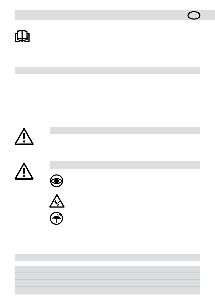
1. Handgri
2. Schutzkappe
3. Fugenklinge
4. Einstellrad Fugentiefe
5. Ersatz-Schutzkappe
6. Klingenhalter
7. Klemmschraube
8. 2 mm-Sechskant-Stiftschlüssel
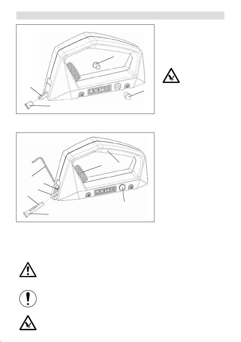
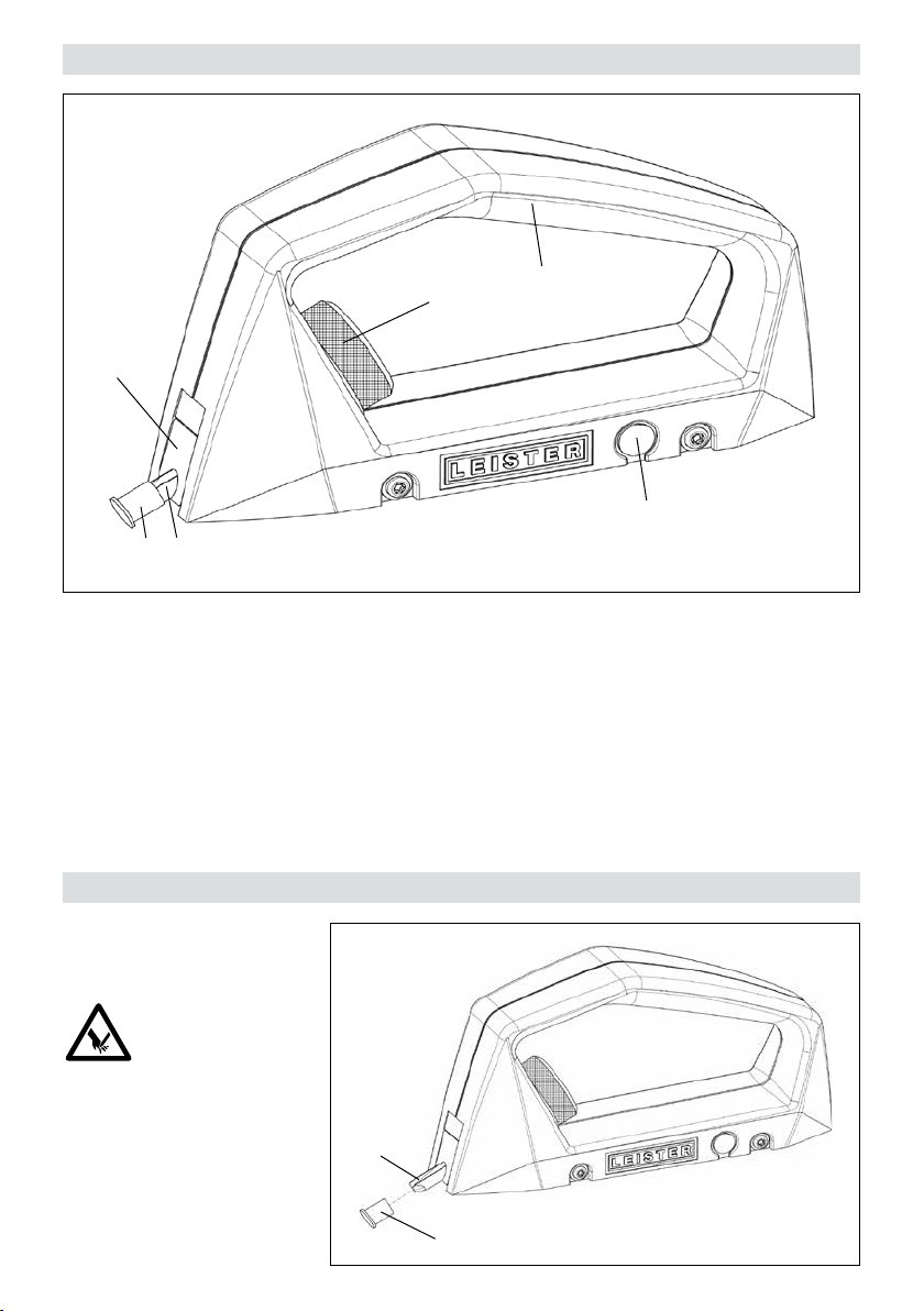
Um die Klinge zu ersetzen, muss
der Klingenhalter (6) bis zum An-
schlag herausgefahren werden.
Dazu muss das Einstellrad (4) im
Gegenuhrzeigersinn (+) gedreht
werden. Diese Einstellung legt die
Klemmschraube (7) frei. Dann
Klemmschraube (7) ¼-Umdre-
hung lösen und Fugenklinge (3)
herausnehmen. Neue Fugenklin-
ge (3) einsetzen, flachen Anschli
bündig zur Schraubenachse aus-
richten und mit Klemmschrau-
be (7) festschrauben.
ACHTUNG!
Beim Hantieren mit der Fugenklinge (3) muss die Schutzkappe (2) aufgesteckt sein.
ACHTUNG!
Damit eine präzise, qualitativ erstklassige Fuge gewährleistet werden kann, muss die Fugenklinge (3)
rechtzeitig ersetzt werden. Dies vermindert auch die von einer stumpfen Fugenklinge (3) ausgehende
Verletzungsgefahr.
ACHTUNG!
Der Handfugenhobel GROOVY darf nur mit der im Lieferumfang enthaltenen Fugenklinge eingesetzt
werden.
87
4
6
3
2
1
5
5
5
2
3

8
• Reparaturen sind ausschliesslich von autorisierten Leister Service-Stellen ausführen zu lassen. Diese gewähr-
leisten einen fachgerechten und zuverlässigen Reparatur-Service mit Original-Ersatzteilen.
• Für dieses Gerät gelten die vom direkten Vertriebspartner/Verkäufer gewährten Garantie- oder Gewährleistungs-
rechte ab Kaufdatum. Bei einem Garantie- oder Gewährleistungsanspruch (Nachweis durch Rechnung oder
Lieferschein) werden Herstellungs- oder Verarbeitungsfehler vom Vertriebspartner durch Ersatzlieferung oder
Reparatur beseitigt.
• Weitere Garantie- oder Gewährleistungsansprüche werden im Rahmen des zwingenden Rechts ausgeschlossen.
• Schäden, die auf natürliche Abnutzung, Überlastung oder unsachgemässe Behandlung zurückzuführen sind,
werden von der Gewährleistung ausgeschlossen.
• Keine Garantie- oder Gewährleistungsansprüche bestehen bei Geräten, die vom Käufer umgebaut oder verändert
wurden.
Service und Reparatur
Gewährleistung

9
Read the operating manual carefully before commissioning
and keep it on hand for later consultation.
Operating manual (Translation of the original operating instructions)GB
Protect the GROOVY gouging tool against dirt and moisture.
Grooving tool GROOVY
• Groove preparation without milling
• Groove gouging up to connecting walls
• Clean transition from machine-milled groove to the closure
• Ideal for surfaces that are small and dicult of access
• Precise working thanks to roller guide and adjustable groove depth
Warning
Technical data
Groove width 3.5 mm (0.14 inch) U-shape
Groove depth max. 3 mm
Material PVC and Linoleum
We reserve the right to make technical changes
Caution
Application
The GROOVY gouging tool may be used only with the groove blade included in the scope
of delivery.
Do not touch the groove blade of the GROOVY gouging tool. Doing so could lead
to injuries.
Device is not permitted to be operated unsupervised.
Device may be used only by trained specialists or under their supervision.
Children are not permitted to operate the equipment under any circumstances.

10
Device description
Preparation
1. Handle
2. Protective cap
3. Groove blade
4. Adjustment wheel, groove depth
5. Replacement protective cap
6. Blade holder
Carefully remove the protecti-
ve cap (2).
CAUTION!
Do not touch the groove blade
(3). Doing so could lead to inju-
ries.
1
5
32
6
4
2
3

11
Adjustment, groove depth
The groove depth is to be tailo-
red to the material to be wel-
ded.
Rotating the adjustment wheel
(4) counterclockwise yields a
deeper groove (+), rotating the
adjustment wheel (4) clockwise
yields a groove of lesser depth
(-). Each revolution results in a
change of depth of around 0.35
mm.
If the blade holder (6) is flush
with the housing, then the blade
will achieve a cutting depth of
around 0.5mm.
If the blade holder (6) is com-
pletely extended, then the blade
will achieve a maximum cutting
depth of around 3.0mm.
4
6
6

12
Application
The device is guided along the
groove that has already been cut
with the help of the integrated
guide rollers.
Executing clean grooves up to
connecting walls.
Precise working thanks to roll-
er guide and adjustable groove
depth.

13
Maintenance
CAUTION!
If not used, the groove blade (3)
must always be secured with the
protective cap (2) because of the
danger of injury.
A protective cap (2) that has
been lost or which exhibits great
wear must be replaced with one
of the two replacement protec-
tive caps (5).
The replacement caps are also
available as spare parts.
1. Handle
2. Protective cap
3. Groove blade
4. Adjustment wheel, groove depth
5. Replacement protective cap
6. Blade holder
7. Clamping screw
8. 2 mm hexagon wrench key
To replace the blade, the blade
holder (6) must be extended out
to the stop. To accomplish this,
the adjustment wheel (4) must
be rotated counterclockwise (+).
This setting exposes the clamp-
ing screw (7). Then loosen the
clamping screw (7) with a ¼
revolution and remove the groove
blade (3). Insert new groove
blade (3), align flat polish sec-
tion flush with the screw axis and
screw tightly with the clamping
screw (7).
CAUTION!
When handling the groove blade (3), the protective cap (2) must be fitted.
CAUTION!
In order to be able to ensure a precise, high-quality joint, the groove blade (3) must be replaced
when it is time to do so. This also reduces the danger of injury arising from a blunt groove blade (3).
87
4
6
3
2
1
5
5
5
2
3

14
• Repairs shall be assigned exclusively to authorized Leister Service points. These guarantee a professional and
reliable repair service with original spare parts in accordance with circuit diagrams and spare parts lists.
• For this tool, the guarantee or warranty rights granted by the relevant distributor/seller shall apply. In case of
guarantee or warranty claims any manufacturing or workmanship defects will either be repaired or replaced by
the distributor at its discretion. Warranty or guarantee rights have to be verified by an invoice or a delivery docu-
ment. Heating elements shall be excluded from warranty or guarantee.
• Additional guarantee or warranty claims shall be excluded, subject to mandatory provisions of law.
• Warranty or guarantee shall not apply to defects caused by normal wear and tear, overload or improper handling.
• Warranty or guarantee claims will be rejected for tools that have been altered or changed by the purchaser.
Service and repair
Warranty

15
Prima della messa in servizio leggere attentamente le presenti istruzioni per l’uso
e conservarle per una futura consultazione.
Istruzioni per l’uso (Traduzione delle istruzioni per l’uso originali)I
La sgorbia per fughe GROOVY deve essere protetta da sporcizia e umidità.
Sgorbia per fughe GROOVY
• Preparazione delle fughe senza fresatura
• Sgorbiatura fino alla terminazione della parete
• Transizione in completa pulizia dalla fuga eseguita con la fresatrice meccanica alla terminazione della parete
• Ideale per le superfici piccole e di dicile accesso
• Precisione operativa grazie alla guida rullo e alla profondità regolabile della fuga
Non toccare la lama di sgorbiatura della sgorbia per fughe GROOVY. Ciò potrebbe
provocare ferite.
L’apparecchio deve essere azionato sotto controllo visivo.
L’impiego dell’apparecchio è consentito esclusivamente a personale qualificato
o sotto il monitoraggio di quest’ultimo. È tassativamente vietato l’impiego da parte
dei bambini.
Avvertenza
Specifiche tecniche
Larghezza fuga 3,5 mm (0,14 pollici), a forma di U
Profondità fuga max. 3 mm
Materiali PVC e linoleum
Modifiche tecniche riservate
Attenzione
Applicazione
La sgorbia per fughe GROOVY deve essere utilizzata esclusivamente con la lama di sgor-
biatura fornita in dotazione.

16
Descrizione dell’apparecchio
Operazioni preliminari
1. Impugnatura
2. Cappuccio protettivo
3. Lama di sgorbiatura
4. Ghiera di regolazione profondità fuga
5. Cappuccio protettivo sostitutivo
6. Portalama
Rimuovere con attenzione
il cappuccio protettivo (2).
ATTENZIONE!
Non toccare la lama di sgorbia-
tura (3).Ciò potrebbe provocare
ferite.
1
5
32
6
4
2
3

17
Regolazione della profondità della fuga
La profondità della fuga deve
essere dimensionata in base al
materiale da saldare.
Se la ghiera di regolazione (4)
è ruotata in senso antiorario, la
fuga risulterà più profonda (+);
se la ghiera di regolazione (4)
è ruotata in senso orario, la fuga
risulterà meno profonda (-). Una
rotazione completa produce una
variazione di profondità pari a cir-
ca 0,35mm.
Se il portalama (6) è in linea con
l’alloggiamento, la lama raggiun-
ge una profondità di taglio di circa
0,5mm.
Se il portalama (6) è comple-
tamente estratto e in battuta, la
lama raggiunge una profondità di
taglio di circa 3,0mm.
4
6
6

18
Applicazione
L’apparecchio viene guidato nella
fuga già realizzata mediante gli
appositi rulli di guida integrati.
Esecuzione pulita delle fughe fino
alla terminazione della parete.
Precisione operativa grazie alla
guida rullo e alla profondità rego-
labile della fuga.

19
Manutenzione
ATTENZIONE!
Per prevenire eventuali lesioni, quan-
do la lama di sgorbiatura (3) non è
in uso, deve essere sempre coperta
con il cappuccio protettivo (2).
I cappucci protettivi(2) smar-
riti o molto usurati devono essere
sostituiti con uno dei due cap-
pucci protettivi sostitutivi (5).
È possibile ordinare altri cap-
pucci protettivi come parti di
ricambio.
1. Impugnatura
2. Cappuccio protettivo
3. Lama di sgorbiatura
4. Ghiera di regolazione
profondità fuga
5. Cappuccio protettivo sostitutivo
6. Portalama
7. Vite di fermo
8. Chiave esagonale da 2mm
Per sostituire la lama, il portala-
ma (6) deve essere estratto fino
alla battuta. A tale scopo, ruotare
la ghiera di regolazione (4) in
senso antiorario (+). Questa im-
postazione consente di svincolare
la vite di fermo (7). Allentare
quindi la vite di fermo (7) di ¼
di giro ed estrarre la lama di
sgorbiatura (3). Inserire la nuova
lama di sgorbiatura (3), allinea-
re la superficie piana alata con
l’asse della vite e serrare agendo
sulla vite di fermo (7).
ATTENZIONE!
Durante la manipolazione della lama di sgorbiatura (3) il cappuccio protettivo (2) deve essere
sempre applicato.
ATTENZIONE!
Per ottenere fughe perfette e di qualità superiore, la lama di sgorbiatura (3) deve essere sostituita
regolarmente. Una puntuale sostituzione riduce anche il rischio di lesioni procurato da lame di sgor-
biatura (3) smussate.
87
4
6
3
2
1
5
5
5
2
3

20
• Le riparazioni devono essere eseguite esclusivamente dai centri di assistenza autorizzati da Leister. Questi
ultimi assicurano riparazioni sicure e adabili, con parti di ricambio originali come da schemi elettrici ed elenchi
parti di ricambio.
• A questo prodotto si applicano i diritti previsti per la garanzia concessi dal partner di distribuzione/rivenditore di-
retto, a partire dalla data di acquisto. In caso di ricorso alla garanzia (fanno fede la fattura o la bolla di consegna),
sono previste la fornitura sostitutiva o la riparazione di difetti di fabbricazione o di lavorazione a cura del partner
di distribuzione. La garanzia non si applica agli elementi riscaldanti.
• È esclusa qualsiasi ulteriore garanzia non espressamente prevista dalle vigenti norme di diritto cogente.
• Sono esclusi dalla garanzia i danni riconducibili alla naturale usura, al sovraccarico o alla scorretta manipolazione.
• Il ricorso alla garanzia decade per gli apparecchi sottoposti a modifiche o alterazioni da parte dell’acquirente.
Assistenza e riparazioni
Garanzia legale
Table of contents
Languages:
Other Leister Cutter manuals