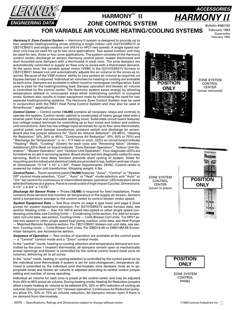
Lennox Harmony III User manual

HARMONY III™ zoning system (X9953)
Installation, Setup and User Guide
507936-01 6/2021
Supersedes 7/2019
2021©Lennox Industries Inc.
Dallas, Texas, USA

2
1.10.9.1. Gas Furnace and Air Conditioning...................................................... 13
1.10.9.2. Heat Pump with Electric Backup Heat ................................................ 13
1.10.9.3. Heat Pump - Dual Fuel heating, 1-stage or 2 Stage Heat Pump and
Gas Furnace ....................................................................................... 13
1.11. Common System Component Wiring...............................................................13
1.11.1. Dampers and Damper Transformer .................................................................... 13
1.11.2. Discharge Air Sensor (DAS) Probe ..................................................................... 14
1.12.ComponentSpecicWiring..............................................................................14
1.12.1. Zone Control Transformer Phasing ..................................................................... 14
1.12.2. Thermostat .......................................................................................................... 15
1.12.3. Gas Furnace ....................................................................................................... 15
1.12.4. Air Conditioner Unit ............................................................................................. 15
1.13. Minimum CFM in Variable Speed Furnace and Air Handlers...........................16
1.14. System Flow Diagrams ....................................................................................17
2. Heat Pump ............................................................................. 18
2.1. Installing Heat Pump and Accessories...............................................................18
2.1.1. Equipment Installation......................................................................................... 18
2.1.2. Pressure Switch .................................................................................................. 18
2.1.3. Pressure Switch Wiring ...................................................................................... 18
2.1.4. Tee (High Pressure Switch; Heat Pumps only) ................................................... 18
2.1.5. Balance Point Sensor (Outdoor Thermostat)...................................................... 18
2.1.6. Defrost Tempering Kit.......................................................................................... 19
2.2. Variable Speed Motor (VSM) Air Handler and Heat Pump - Option 2
(Zoning System).................................................................................................20
2.3. Heat Pump System Start-Up and Checkout.......................................................21
2.3.1. Powering the System (All Systems) .................................................................... 21
2.3.2. Checkouts ........................................................................................................... 21
2.3.2.1. Typical Heat Pump Heating Checkout (Single Zone).......................... 21
2.3.2.2. Typical Heat Pump Heating Checkout (Multiple Zone) ....................... 22
2.3.2.3. Typical Heat Pump Heating Checkout (Central Mode) ....................... 23
2.4. Heat Pump System Start-Up and Checkout.......................................................24
2.4.1. Troubleshooting Diagram.................................................................................... 24
2.4.2. Heat Pump Heating Operation............................................................................ 25
2.4.3. Defrost Operations .............................................................................................. 25
3. Gas Furnace .......................................................................... 26
3.1. Typical Wiring for Variable-Speed Gas Furnace and Outdoor AC Unit - Option 126
3.2. Furnace Variable Speed Motor Electrical Adjustments ......................................27
3.3. Variable Speed Motor Furnace System Operations...........................................27
Table of Contents
1. General..................................................................................... 4
1.1. Shipping and Packing List....................................................................................4
1.2. Acronyms Used....................................................................................................4
1.3. Additional Parts Required ....................................................................................4
1.4. Introduction ..........................................................................................................4
1.5. Residential Zone Control System - Overview of Field Wiring ..............................5
1.6. System Components............................................................................................5
1.6.1. Zone Control System ............................................................................................ 5
1.6.2. Discharge Air Sensor (DAS).................................................................................. 6
1.6.3. Thermostats .......................................................................................................... 6
1.6.4. Transformers......................................................................................................... 6
1.6.5. Dampers................................................................................................................ 6
1.6.6. Remote Vacation Switch ....................................................................................... 6
1.7. Installation Planning and Selecting Heating and Cooling Equipment ..................7
1.7.1. Installation Considerations ................................................................................... 7
1.7.2. Variable Speed Blower Motor (VSM) .................................................................... 7
1.7.3. Selecting/Installing Indoor and Outdoor Units ...................................................... 7
1.8.OptionalDehumidicationAccessories................................................................7
1.9. Installing Zone Control Components....................................................................7
1.9.1. Discharge Air Sensor (DAS).................................................................................. 7
1.9.2. Zone Control Panel ............................................................................................... 8
1.9.3. Thermostats .......................................................................................................... 8
1.9.4. Transformer........................................................................................................... 8
1.9.5. Dampers................................................................................................................ 8
1.9.6. Zone Linking.......................................................................................................... 8
1.10. Zone Control Panel Jumpers..............................................................................9
1.10.1. Setup for Controlling Equipment Staging and Volume of Air to Zones ................. 9
1.10.2. PIAB Jumpers Affect Blower Operation ................................................................ 9
1.10.3. Upgrading from Harmony II zoning system?....................................................... 10
1.10.4. Zone 1 PIAB Jumpers – 140ºF DAS ................................................................... 10
1.10.5. Determining PIAB Jumper Settings..................................................................... 10
1.10.6. Continuous Air Reduction Jumpers......................................................................11
1.10.7. Heating Air Reduction Jumpers............................................................................11
1.10.8. Heat/Cool Staging................................................................................................11
1.10.8.1. Heating Staging Temperature Jumper .................................................11
1.10.8.2. Cooling Staging Temperature Jumper ................................................ 12
1.10.9.SystemConguration/E-HeatStages) ................................................................ 13

3
3.3.1. Operation ............................................................................................................ 27
3.3.2. Integrated Furnace Control W2 terminal to Harmony III zoning system
Control................................................................................................................. 28
3.3.3. Installation Setup Worksheets............................................................................. 28
3.3.3.1. SLP98V — Cooling/Heating (Non-Heat Pump Applications) .............. 28
3.3.3.2. SL280V, SL280NV, EL296V and SL297NV — Cooling/Heating
(Non-Heat Pump)................................................................................ 29
3.3.4. Zone Control Operation in a Gas Furnace System............................................. 30
3.3.4.1. Zone Thermostats............................................................................... 30
3.3.4.2. Balance Point Setting.......................................................................... 30
3.3.4.3. Zone Mode.......................................................................................... 31
3.3.4.4. Central (Vacation) Mode ..................................................................... 31
3.3.4.5. Cooling Operation ............................................................................... 31
3.3.6. Installation Setup Worksheets for Honeywell 2-Stage IFC Control — Cooling/
Heating (Non-Heat Pump)................................................................................... 31
3.4. Furnace System Start-Up and Checkout ...........................................................33
3.4.1. Start-Up the System (All Models)........................................................................ 33
3.4.2. Checkouts ........................................................................................................... 33
3.4.2.1. Typical Gas Heating Checkout (Single Zone) ..................................... 33
3.4.2.2. Typical Gas Heating Checkout (Multiple Zone)................................... 34
3.4.2.3. Typical Gas Heating Checkout (Central Mode)................................... 35
3.5. Zoning System with Gas Furnace Troubleshooting - Option 1...........................36
3.5.1. Troubleshooting Diagrams .................................................................................. 36
3.5.2. Gas Heating Operation ....................................................................................... 38
3.5.3. Discharge Air Upper Limit and Differential Temperatures ................................... 38
4. Air Handlers........................................................................... 39
4.1. Variations on Common AC Unit Applications .....................................................39
4.1.1. Heating/Cooling Equipment Installation .............................................................. 39
4.1.2. Air Handler Wiring ............................................................................................... 39
4.1.3. Variations ............................................................................................................ 39
4.2. Electrical Adjustments........................................................................................40
4.2.1. Communicating Indoor Control ........................................................................... 40
4.2.2. Non-Communicating Indoor Control.................................................................... 40
4.2.3. Installation Worksheets ....................................................................................... 42
4.2.3.1. Cooling/Heating with Electric Strip Heat (Non-Heat Pump) ................ 42
4.2.3.2. Heat Pump — Electric Strip Heat ....................................................... 44
4.2.3.3. Cooling Only or Cooling with Hot Water Coil (Non-Heat Pump) ......... 46
5. Dual Fuel (Option 3).............................................................. 48
5.1. Zone Control System Wiring - Option 3 .............................................................48
5.2. Dual Fuel System Start-Up Defrost Temperating Sensor Placement and
Checkout............................................................................................................49
5.2.1. Start-Up the System (All Models)........................................................................ 49
5.2.2. Defrost Temperating Sensor Placement ............................................................. 49
5.2.3. Checkouts ........................................................................................................... 50
5.2.3.1. Typical Dual Fuel Gas Heating (Single Zone)..................................... 50
5.2.3.2. Typical Dual Fuel Gas Heating (Multiple Zone) .................................. 51
5.2.3.3. Typical Dual Fuel Gas Heating (Central Mode) .................................. 52
5.3. Zoning System with Dual Fuel Troubleshooting - Option 3................................53
5.3.1. Troubleshooting Diagram.................................................................................... 53
5.3.2. Dual Fuel Operation (Below Balance Point)........................................................ 54
5.3.3. Discharge Air Upper Limit and Differential Temperatures ................................... 54
5.3.4. Dual Fuel Operation (Above Balance Point) ....................................................... 55
5.3.5. Defrost Operation................................................................................................ 55
5.3.6. Installation Setup Worksheets............................................................................. 56
5.3.6.1. Dual Fuel - Indoor Unit Honeywell 2-Stage IFC Control and Heat
Pump 56
5.3.6.2. Dual Fuel - SLP98 Variable Capacity and Heat Pump........................ 57
5.3.6.3. Dual Fuel - Variable Speed SL280V, EL296V, SL297NV and
Heat Pump .......................................................................................... 58
6. Troubleshooting.................................................................... 59
6.1. Operation and Troubleshooting Indicators .........................................................59
6.1.1. Zone Control Panel LEDs ................................................................................... 59
6.1.2. Fault Recall and Time Delay Override ................................................................ 60
6.1.3. Time Delays ........................................................................................................ 60
6.1.4. Discharge Air Probe Checkout (All Systems)...................................................... 60
6.1.5. Blower Speed Checkout...................................................................................... 61
6.2. Diagnostic LED Error Codes..............................................................................62
6.3. Air Delivered By Blower .....................................................................................63
6.3.1. Formulas ............................................................................................................. 63
6.3.2. PIAB Calculation Worksheet ............................................................................... 65
7. AirowData ........................................................................... 66
8. User Guide............................................................................. 77
8.1. What is the Harmony III™ zoning system? .......................................................77
8.2. What does the Harmony III™ zoning system consist of?...................................77
8.3. How do I set the Control Center Switches? ......................................................77
8.4. How do I use the Thermostat Controls?.............................................................77
8.5. How do I use the Central (Vacation) Mode? ......................................................77
4
8.6. How do I use the Zone Mode?...........................................................................78
8.7. How are Zones Determined? .............................................................................78
8.8. How do I use the Optional Humiditrol®DehumidicationAccessory?................78
8.9. Enabling and Disabling Humiditrol Setting in Thermostat ..................................78
8.10. Humiditrol User Adjustment is also available under the User Settings.............78
8.11. Owner Reminder! ............................................................................................78
8.12. Thermostat replacement ..................................................................................78
8.13. Maintenance.....................................................................................................78
8.14. Homeowners Zone Information Record ...........................................................79
1. General
1.1. Shipping and Packing List
Table 1. Packing List
Quantity Description
1 Harmony III zoning system unit
1Discharge Air Sensor
1 Installation Instruction
1 Warranty (W-031-L2-02)
1.2. Acronyms Used
Table 2. Acronyms
Acronym Description
AC Air Conditioner
CFM Cubic Feet per Minute
DAS Discharge Air Sensor
DF Down Flow
EDA EnhancedDehumidicationAccessory
HZA Humiditrol Zoning Accessory Kit
IFC Integrated Furnace Control
PIAB Percentage into Adjustment Band
PWM Pulse Width Modulated
UH Up Flow
VSM Variable Speed Motor
1.3. Additional Parts Required
Table 3. Additional Parts
Quantity Description
Application
specic
Transformer
Dampers
Thermostats
Balance Point Sensor kit (10Z23)
Pressure switch (For Heat Pump Option): HFC-22 (27W12); HFC-410A (27W13
Tee for vapor line High Pressure Switch (87071)
Defrost Tempering Kit (67M41)
Humiditrol®EnhancedDehumidicationAccessory(EDA),EDA-024B(94M41),
EDA-036C (94M42), EDA-060D (94M43)
Humiditrol® Zoning Accessory Kit (39W67) (required if Humiditrol®EDA, above, is
used)
NOTE: Due to Lennox’ ongoing commitment to quality, features and options are
subject to change without notice and without incurring liability. Improper
installation, adjustment, alteration, service or maintenance can cause
property damage or personal injury. Installation and service must be
performed by a qualied installer and servicing agency.
1.4. Introduction
IMPORTANT
Variable Speed Blower Motor (VSM) technology is required for use with Harmony
III zoning system.
The Lennox Harmony III zoning system manages the distribution of conditioned
airtospecicareasorzonesinahouseorsmallcommercialbuildingbydirecting
heated or cooled air to occupied areas without conditioning unused areas. The
system can be used in the following Lennox HVAC system applications:
Table 4. System Applications
Option Description
1 Variable speed gas furnace used with a 2-stage air conditioner unit. *
2 Variable speed air handler unit (with or without electric heat) used with a 2-stage air
conditioner unit or heat pump. *
3 Variable speed gas furnace used with a 2-stage heat pump (dual fuel).*
*A1-stageairconditionerunit(heatpump)maybeusedunderspeciccircumstancesaslistedin
“Table 8. Lennox AC or Heat Pump Units” on page 7.
Variations on the options described above and included in this document are
cooling-only, hot water coil and cooling system with electric heat applications.
The Harmony III zoning system uses off-the-shelf, single-stage, non-heat pump,
non-power-robbing electronic thermostats and motorized dampers in any of the
applications to control distribution of conditioned air to different zones. This control

5
allows conditioning of different zones within a residence while using a single HVAC
system. The zone control system operates in two modes: central control (vacation
mode) or zone control. LEDs on the zone control panel indicate the current
operating mode.
When the system is in the central control mode, a demand from the central control
thermostat results in conditioned air being directed to all of the zones. In this mode,
zone 1 thermostat is designated as the controlling thermostat; other thermostats
are not used. When the system is in the zone control mode, a zone is conditioned
only upon demand from that zone’s thermostat. The zone control system is ideal for
retrotapplicationsaswellasnewconstruction.Thesystemcontrolstheairvolume,
eliminating the need for bypass dampers in most applications. The homeowner
controls the system using zone thermostats to make comfort settings for each
zone. A programmable thermostat should be used to provide a specialized heating
and cooling sequence. While the system is in the zone mode, a programmable
thermostat controls the temperature for its particular zone.
1.5. ResidentialZoneControlSystem-OverviewofField
Wiring
VARIABLE SPEED
FURNACE OR AIR
HANDLER
ZONE 1ZONE 2
*ZONE 4
POWER
THERMOSTAT (ZONE 1 OR CENTRAL CONTROL
THERMOSTAT WHEN IN VACATION MODE)
ZONE DAMPER
THERMOSTAT
(ZONE)
CONDENSING
UNIT OR HEAT
DOOR UNIT
TRANSFORMER TO POWER
MOSTATS AND DAMPERS;
ALSO POWERS HZA CONTROL
WHEN EDA IS USED)
THERMOSTAT
(ZONE)
LEGEND -
AFive wire low voltage — 18 ga. minimum
BTwo wire low voltage OR Three wire if Power-open, Power-closed — 18 ga. minimum
CINDOOR UNIT: Up to nine wire low voltage — 18 ga. minimum
DOUTDOOR UNIT:
- Two (3, if LSOM equipped unit) wire low voltage (single‐stage condensing unit or EDA) 18 ga. minimum
- Three (4, if LSOM equipped unit) wire low voltage (two‐stage condensing unit) 18 ga. minimum
- Up to seven wire low voltage (single‐stage heat pump outdoor unit) 18 ga. minimum
- Up to eight wire low voltage (two‐stage heat pump outdoor unit) 18 ga. minimum
ETwo wire low voltage (discharge air sensor) 18 ga. minimum
FTwo wire low voltage (pressure switch, heat pump only) — 18 ga. minimum
GTwo wire — 18 ga. minimum
HRefer to the Humiditrol® Zoning Accessory (HZA) for wiring requirements.
*NOTE - Zone 3 and zone 4 not available with single‐stage outdoor unit.
OUTDOOR
THERMOSTAT /
BALANCE
POINT SENSOR
ZONE CONTROL
SYSTEM PANEL
A
B
DISCHARGE
AIR SENSOR
E
C
D
F
ZONE DAMPER
G
*ZONE 3
THERMOSTAT
(ZONE)
ZONE DAMPER
ZONE DAMPER
HUMIDITROL®ENHANCED
DEHUMIDIFICATION
ACCESSORY HUMIDITROL®
ZONING
ACCESSORY (HZA)
OPTIONAL
H
A
B
B
A
B
A
B
Figure 1. Field Wiring
1.6. System Components
The Harmony III zoning system consists of the following (required):
• Harmony III zoning system zone control panel (included)
• Discharge Air sensor (included)
• Thermostats (one for each zone; ordered separately)
• 24VAC Power Transformer(s) (ordered separately)
• Dampers (ordered separately)
• Pressure Switch and Tee with Schrader valve (for Heat Pump systems; ordered
separately)
• Balance Point Sensor (Optional for Dual Fuel systems)
• Defrost Tempering Kit (Optional for Dual Fuel systems)
• Remote Vacation Switch (optional; ordered separately)
1.6.1. Zone Control System
The Harmony III zoning system monitors electrical signals and directs control
signals between thermostats, dampers, and HVAC equipment.
JUMPERS:
STAGING
TEMP`
HEATING--
COOLING--
AIR
REDUCTION
CONT.--
HEATING--
EQUIPMENT
CONNECTIONS
THERMOSTAT
CONNECTIONS
24VAC
CONNECTIONS
PIAB
JUMPERS
SYS CONFIG AND
E-HEAT JUMPERS
DIAGNOSTIC
LEDS
TIME
DELAY
RIDE
FAULT
RECALL
OUTDOOR THERMOSTAT /
BALANCE POINT SENSOR
CONNECTIONS
PRESSURE
NECTIONS
DISCHARGE
AIR SENSOR
CONNECTIONS
DAMPER
TIONS
FUSES
SYSTEM OPERATION LEDS
REMOTE
VACATION
SWITCH;
CONNECTIONS
FOR HZA
Figure 2. Harmony III Zoning System Zone Control Panel

6
1.6.2. Discharge Air Sensor (DAS)
A discharge air temperature sensor (19V99) monitors the supply air. This electronic
sensor’s probe is inserted into the discharge air plenum to gather air temperature
data for the zone control panel. “Figure 4. Discharge Air Sensor Installation” on
page 8 for location of the sensor.
TEMPERATURE/RESISTANCE CHART
TEMP ºF RESISTANCE (OHMS)
30 34,566
40 26,106
50 19,904
60 15,313
70 11.884
80 9,298
90 7,332
100 5,826
Figure 3. Discharge Air Sensor
1.6.3. Thermostats
IMPORTANT
Use only Electronic thermostats. Mechanical or electro-mechanical thermostats
will not work with the Harmony III zoning system.
For all zones, use thermostats that are of this type:
• Electronic thermostat
• Single-stage
• Non-heat pump
• Non-power robbing
• Auto-changeover or non auto-changeover
• Lennox recommends that zone 1 thermostat (central [vacation] mode controller)
be programmable.
• Each thermostat must have a deadband between HEAT and COOL.
Recommended thermostats include:
• ComfortSense®5500 (13H13) 7-Day Programmable Touch Screen Thermostat
- 1 heat / 1 cool
• ComfortSense®7500 (13H14) 7-Day Programmable Touch Screen Thermostat
-4Heat / 2 Cool (conguredfornon-heatpump operation). When using this
thermostat,onlyPrecisionModedehumidicationcanbeusedwherein2°Fof
over-cooling is allowed. Also, it cannot reduce the blower speed because the
zone control DS signal controls the blower. Thermostat Dterminal is not used.
• iComfort M30 (15Z69) 4 Heat / 2 Cool, Universal Multi-Stage Touch Screen
Thermostat.
1.6.4. Transformers
The dampers, zone control panel, zone thermostats and Humiditrol®Zoning
Accessory (if EDA is used) are powered by a single, eld-provided 24VAC
transformer. Together, the zone control panel and thermostats require 10VA;
dampers require 10VA each. The transformer must have an adequate VA rating to
serve all components as described in the following table.
IMPORTANT
Up to 5 dampers per zone may be connected in parallel to the zone control panel
—not to exceed a total of six dampers for entire system.
Also, if more than 6 dampers are used, another transformer and isolation relay
will be necessary.
Table 5. 24VAC Transformer Selection Chart
Catalog
Number Size Description VA LOAD =
Panel Plus
10P17 40VA 120/208/240VAC, 24VAC 3 dampers
10P87 50VA 120/208/240VAC, 24VAC 4 dampers
12P61 75VA 120/208/240VAC, 24VAC 6 dampers
83P74 _ Electrical Box (4-in. Square)
1.6.5. Dampers
Motorized 24VAC powered closed/spring return open dampers are standard for
the Harmony III zoning system. However, “power-open/spring-close” and “power-
open/power-close” dampers can be accommodated
1.6.6. RemoteVacationSwitch
The Harmony III zoning system control panel includes connections for an optional
remote vacation switch (see “Figure 2. Harmony III Zoning System Zone Control
Panel” on page 5). The same connections are also used for connecting an
optional Humiditrol®Zoning Accessory controller (see Humiditrol®Zoning Accessory
Installation Instructions for details).
NOTE: If a remote vacation switch is connected for routing to a convenient location
for end user operation, be sure the switch (eld-provided) is properly
labeled and instructions provided for proper operation.
IMPORTANT
Do not locate the remote vacation switch next to other house switches! The
recommend location is next to Zone 1 thermostat.

7
1.7. Installation Planning and Selecting Heating and Cooling
Equipment
WARNING
Improper installation, adjustment, alteration, service or maintenance can cause
property damage, personal injury or loss of life.
Installation and service must be performed by a licensed professional HVAC
installer (or equivalent) or a service agency.
1.7.1. Installation Considerations
The total HVAC system must be properly sized to provide the best comfort. Also,
for best performance, zones should be similar in size so that each zone would
require about the same CFM. Each zone’s ducting lengths should be similar in
length whenever possible. Always attempt to keep CFM requirements per zone
within 25% of the average CFM as referenced in the following table.
If a “small” zone cannot be avoided, give consideration to increasing the CFM of
the small zone and linking a damper in a nearby zone that will open along with the
small zone’s damper(s). The procedure for zone linking is described in “1.9.6. Zone
Linking” on page 8.
Table 6. Adjusting for Average CFM Example
Required CFM CFMAdjustedtowithinAverage
Zone CFM Avg %CFM Adj Avg %CFM
1 500 713 0.70 600 738 0.81 Damper linked with Zone 2
2 825 1.16 825 1.12
3 775 1.09 775 1.05
4 750 1.05 750 1.02
1.7.2. VariableSpeedBlowerMotor(VSM)
Indoor units with variable speed “blower” motors (VSM) are required to allow
the zone control system to distribute adequate air to each zone. Use only units
recommended in the following 3 options referenced in “1.7.3. Selecting/Installing
Indoor and Outdoor Units” as only those will work with the Harmony III zoning
system; other types of units will not allow the Harmony III zoning system to
proportion the amount of air going to each zone.
1.7.3. Selecting/Installing Indoor and Outdoor Units
Outdoor units may be single or two-stage; use the following table to determine
which to use, based on the number of zones being implemented, and whether the
air conditioned zones are of equal or unequal size.
Table 7. Indoor / Outdoor Options
Options Indoor Unit Outdoor Unit
1Any Lennox Gas Furnace with VSM
only.
Lennox Air Conditioner unit as described in
“Table 8. Lennox AC or Heat Pump Units”.
2Lennox Air Handler Unit with VSM
only.
Lennox Heat Pump unit as described in
“Table 8. Lennox AC or Heat Pump Units”.
3Any Lennox Gas Furnace with VSM
only.
Lennox Heat Pump unit as described in
“Table 8. Lennox AC or Heat Pump Units”.
NOTE: Limited variations to AC units described herein are detailed. Go to “4.1.
Variations on Common AC Unit Applications” on page 39 for further
details.
Table 8. Lennox AC or Heat Pump Units
Number of
Zones Comparative Zone Sizes Lennox AC or Heat
Pump Unit
2 Equal Single or Two-stage and VSM
units
2 *Unequal Two-stage only and VSM units
3 or 4 Equal or Unequal Two-stage only and VSM units
*Equal zones would have very similar total ducting lengths with CFM requirements within 10% of
average CFM per zone. Unequal would have less similar ducting length and greater variances from
average CFM (see “Table 6. Adjusting for Average CFM Example” on page 7 example).
1.8. OptionalDehumidicationAccessories
The Harmony III zoning system may be used in conjunction with a Humiditrol®
EnhancedDehumidicationAccessory(EDA)andwhichalsorequiresaHumiditrol®
ZoningAccessory(39W67).Thisdocumentreectsthecontrolwhichisoutttedfor
connection to, and control of, the EDA in a zone control system using the HZA. See
Humiditrol®Zoning Accessory Installation Instructions for more information.
1.9. Installing Zone Control Components
1.9.1. Discharge Air Sensor (DAS)
CAUTION
This device is manufactured using unpainted and pre-painted metal. Sharp
sheet metal edges can cause injury. When installing the device, avoid accidental
contact with sharp edges.
Install the discharge air sensor in the discharge plenum downstream from the
cooling coil. Be sure that the discharge air will pass over the sensor before the air
isdistributedintotheductsystem.Typicalup-owsensorapplicationsareshownin
gure4;thesensordimensionsshown(distancefromheatstrips,coil,andposition
in plenum) also apply to other applications.

8
1. When possible, position the sensor some distance away from the coil rather
than in the immediate coil area. The discharge air sensor should be located at
least 10 inches above the coil if possible.
2. Fasten the sensor bracket to the plenum with two self-tapping sheet metal
screws.
3. Connect wires to DAS on zone control panel. Not on the air handler control
or IFC (see “Figure 20. Option 2 - Typical Lennox Heat Pump and Lennox
Variable-Speed Air Handler (Troubleshooting)” on page 20 ).
4. Be sure that the tip of the sensor is located approximately 10 inches from the
indoor coil in the discharge plenum, and half the depth of the plenum, and
centeroverthedischargeairow,side-to-side.
IMPORTANT
For the DAS, transversing the supply duct for the best location is recommended.
Optimal location is critical to the proper operation of the zoning system
plenum
coil
INDOOR
UNIT FRONT
VIEW
sensor centered in
discharge airflow
(see note 1)
Temperature
19
(254)
INDOOR UNIT
SIDE VIEW
ECB
Electric
Heat
Strips
NOTE - FOR UNITS WITH HUMIDITROL— Discharge air sensor
(DAS) MUST be located on the output side of the EDA (if used; see
Humiditrol Zoning Accessory Installation 506064-02)
SENSOR PROBE
see PROBE
MOUNTING
note below
PLENUM
SENSOR
MOUNTING
DETAIL
Fully insert into plenum
Figure 4. Discharge Air Sensor Installation
1.9.2. Zone Control Panel
IMPORTANT
The electrical power source for the zone control system, i.e. the transformer
primary, and furnace or air handler unit must be the same source. In addition, the
zone control system power-up must occur at the same time or before the furnace
or air handler unit is powered up.
Select an installation site for the Harmony III zoning system control considering the
following location parameters:
• Is conveniently accessible and centrally located to facilitate wiring from
thermostats, dampers, pressure switch (if used), and HVAC equipment.
• Is in a non-condensing area (such as a closet).
• Is NOT in a laundry room (nor other room in the house where the humidity would
typically be much higher than the rest of the house).
• IsNOTinanypartofthebuildingwherethetemperaturemayexceed150°F.
1.9.3. Thermostats
Identify the best location for a thermostat in each zone. If two or more rooms are
within a single zone, place the thermostat in a location that is central to all rooms.
For example, if a zone contains two bedrooms, try to place the thermostat in a
hallway near both bedrooms.
Do not install thermostats in drafty areas, behind doors, in corners, near radiant heat
sources (appliances), near sunny windows, near concealed pipes and chimneys,
nor in unconditioned spaces such as closets or exterior walls.
1.9.4. Transformer
Obtain an appropriately-rated transformer (see “Table 5. 24VAC Transformer
Selection Chart” on page 6). Install the transformer in either the indoor unit or
in an electrical junction box near the zone control panel.
NOTE: Two transformer systems need to be in phase with each other.
1.9.5. Dampers
NOTE: The power source for the transformer must be the same power source as
the indoor unit’s transformer.
Motorized dampers in the supply duct system regulate air to the zones. Some
applications will be unique and require more than one damper per zone. If
additional dampers are required, refer to the wiring diagram in “1.12. Component
Specic Wiring” on page 14.Also, if more than six dampers are used, another
transformer and isolation relay will be necessary.
For more effective zone isolation, the return duct system may also be dampered
by zone. Dampers for each zone must be wired in parallel. Install dampers in the
desired locations; then run thermostat wire from the damper to the zone control
panel and damper relays as needed.
1.9.6. Zone Linking
Zone link a small zone to a large zone by wiring dampers in a manner similar to
gure4.Effectively,thisdistributessomeofthesmallzone’sairtoanotherzoneto
reduce the chance of overheating or overcooling the smaller zone. Refer to “Table
8. Lennox AC or Heat Pump Units” on page 7 which shows an example of an
unequal zone and how to adjust to bring it within 25% of the average CFM. Figure

9
4 shows how the dampers may be linked to distribute some of the air from a small
zone into another zone.
Zone 2 (largest zone)
Zone 1 (smallest zone)
This damper is linked to the zone 1
damper; it opens when Zone 1
opens to redirect some air away
from Zone 1 and closes only when
zone 1 damper closes.
RELAY
ZONE 2
DAMPER
DAMPER
DAMPER
All Zone 2
dampers
open only
for calls to
Zone 2
calls for air.
DAMPER
ZONE 1
Note: Zone
Dampers are
Power-Close
type.
Figure 5. Zone Linking
Table 9. Zone Demands to Small and Large Zones
Zone Dampers ZonewithDemand
None Small Sm.& Lg. Large
Small Zone Closed (24V) Open (0V) Open (0V) Closed (24V)
Large Zone
Closed (24V) Open (0V) Open (0V) Open (0V)
Closed (24V) Closed (24V) Open (0V) Open (0V)
NOTE: Zone Dampers are Power-Close type.
1.10. Zone Control Panel Jumpers
1.10.1. Setup for Controlling Equipment Staging and Volume of Air
to Zones
This section provides information for installing jumpers on the zone control panel
jumper banks (see “Figure 6. Zone Control Panel Jumper Banks”). These jumpers
denehowthezonecontrolsystemfunctionstocontrolequipmentstagingandto
deliver the proper amount of CFM to the zones.
HEATING STAGING
JUMPERS
COOLING STAGING
JUMPERS
CONTINUOUS AIR
REDUCTION JUMPERS
HEATING AIR
REDUCTION JUMPERS
PIAB
JUMPERS
SYS CONFIG AND
E-HEAT JUMPERS
Figure 6. Zone Control Panel Jumper Banks
CAUTION
Static electrical discharge will damage electronics.
Discharge static electricity before touching the zone control panel. Touch a
grounded metal object before touching the circuit board.
1.10.2. PIABJumpersAffectBlowerOperation
A variable-speed motor will operate at its minimum speed or at any increment
faster up to its maximum speed. The Percentage Into Adjustment Band (PIAB)
jumpers control the speed variance of the motor. When the zone control’s PIAB
jumpers are set to 0%, the blower operates at the minimum air volume produced
by the air handler and when set to 100%, the blower operates at maximum air
volume produced by the air handler (see your air handler installation instructions
forspecicCFMs).
For example: if an air handler has a minimum air volume of 800 CFM,
and a maximum of 1500 CFM, and the jumper is set to 0%, the air
delivered to the zone will be 800 CFM. Similarly, if the jumper is set to
100%, the air delivered to the zone is 1500 CFM. By placing a jumper
in the 50%
er's minimum and maximum CFM capacities.
PIAB JUMPER = 0%
MIN. 800 CFM
PIAB JUMPER = 100%
MAX. 1500 CFM
(MOTOR RUNS AT
MINIMUM SPEED)
(MOTOR RUNS AT
MAXIMUM SPEED)
(MOTOR RUNS AT VARIABLE SPEEDS)
PIAB JUMPER = 50%
MID. 1150 CFM
Figure 7. VSM Adjustment Band Example

10
By installing jumpers at different % on each PIAB bank, you can direct different
amounts of air volume to each zone. You must jumper a % on zone 1 and at
least one other zone, and you must jumper OFF on unused zones as shown
inthefollowinggure.
Pin shown with
jumper on
ZONE 1 AT 10%.
Pin shown with
jumper on
ZONE 2 AT 0%
(allows min. cfm
airflow).
ZONE 1ZONE 3
PIAB PIAB
ZONE 2ZONE 4
PIAB PIAB
NOTE - Only zones 2,
3, and 4 have an OFF
setting.
ZONES 3
AND 4 ARE
SHOWN
NOT USED
(JUMPERS
SET ON
“OFF”).
Figure 8. PIAB Jumper Settings (Typical)
NOTE: The blower speed may be affected by the reduction jumpers, if installed.
See “1.10.6. Continuous Air Reduction Jumpers” on page 11 for more
details.
1.10.3. Upgrading from Harmony II zoning system?
NOTE: If replacing a Harmony II zoning system, use conversion values in “Table
10. Air Jumper Positions Conversion Chart” to maintain equivalent air
settings when setting up the Harmony III zoning system.
Table 10. Air Jumper Positions Conversion Chart
Model Equivalent Positions (%)
Harmony II zoning
system 25 35 45 55 65 75 85 95
Harmony III zoning
system 0 10 30 40 50 70 80 90
1.10.4. Zone 1 PIAB Jumpers – 140ºF DAS
Zone 1 PIAB terminal strip has an additional jumper setting (labeled 140F DAS)
that may be used for added operational exibility (see “Figure 9. 140ºF DAS
Jumper”). When the supplied jumper is in place across both pins, the discharge air
sensor(DAS)upperlimitwillbe140°Finsteadof160°F(default)toprovideadded
operationalexibility.
HEATING STAGING
JUMPERS
COOLING STAGING
JUMPERS
CONTINUOUS AIR
REDUCTION JUMPERS
HEATING AIR
REDUCTION JUMPERS
PIAB
JUMPERS
Figure 9. 140ºF DAS Jumper
NOTE: If the heating staging jumper is set to either 120 or 130 and the 140F DAS
jumper is in place, the furnace will stage up at 115ºF and down to 130ºF
(see “1.10.8.1. Heating Staging Temperature Jumper” on page 11) for
further details.
1.10.5. Determining PIAB Jumper Settings
NOTE: Use “6.3.2. PIAB Calculation Worksheet” on page 65 (also see example
below) to help calculate the zone control system PIAB settings.
1. From a cooling load analysis, determine what CFM is required for each zone.
Also, from the air handler, determine its minimum and maximum CFM ratings.
2. UsingthePIABformula,foundinTable5andreectedintheworksheetbelow,
calculate the Percent Into Adjustment Band (PIAB) using the values from step
1 for each zone. “Determine PIAB Jumper Settings” on page 11 also gives
example CFM values to illustrates how to determine the correct jumper for the
PIAB for Zone 1 using those values.
3. Set the air selection jumper for the zone using the percent air determined in
step 2. If the percent air falls between available jumper settings, select the
nearest unit of ten.
4. For each zone, repeat steps 1 through 3.
NOTE: See “1.10.4. Zone 1 PIAB Jumpers – 140ºF DAS” or information on 140F
DAS (discharge air sensor) jumper used on Zone 1 PIAB.

11
PIAB = [(Required CFM - Minimum CFM) / (Maximum CFM - Minimum CFM)] * 100
Sample CFM RequiredMinimum Maximum Minimum
Sample PIAB = ([___920 -450 ] / [ 2000 -450 ]) x 100
==
Sample PIAB =([470 ] / [1550]) x 100
=
Sample PIAB =[0.303] x 100 = 30 %
Figure 10. PIAB Calculation Example
example
example
CFM
CFM
values
values
Require
Require
d
d
CF
CF
M
M
CFM
CFM
Zon
Zon
e
e
1
1
Zone
Zone
2
2
Zone
Zone
3
3
Zone
Zone
4
4
Min.
Min.
Max.
Max.
1020
1020
1500
1500
720
720
OFF
OFF
720
720
2200*
2200*
*High cool jumper settin
g
g
PIA
PIA
B
B
formula
formula
100
100
(R
(R
e
e
q’
q’
d
d
CFM
CFM
−
−
min. C
min. C
FM
FM
)
)
(Max. CFM
(Max. CFM
−
−
min. CFM
min. CFM
)
)
x
x
U
U
s
s
i
i
ng e
ng e
x
x
a
a
m
m
p
p
l
l
e v
e v
a
a
lue
lue
s
s
abo
abo
v
v
e,
e,
fi
fi
nd
nd
PIAB
PIAB
f
f
o
o
r
r
Zone 1
Zone 1
:
:
PIA
PIA
B
B
(
(
1
1
02
02
0
0
-
-
7
7
2
2
0
0
)
)
= 30
= 30
0
0
=.20
=.20
.
.
.
.
.
.
.
.
..
..
.
.
..
..
.
.
.
.
.
.
..
..
.
.
.
.
.
.
.
.
.
.
...
...
.
.
..
..
.
.
..
..
.
.
(2220 - 720) =150
(2220 - 720) =150
0
0
.
.
.
.
.
.
.
.
..
..
.
.
..
..
.
.
.
.
.
.
..
..
.
.
.
.
.
.
.
.
.
.
.
.
.
.
.
.
.
.
PIAB Jumper setting
PIAB Jumper setting
%
%
.20 x 10
.20 x 10
0
0
20%
20%
.
.
.
.
.
.
.
.
..
..
.
.
.
.
.
.
..
..
.
.
.
.
...
...
.
.
..
..
.
.
Figure 11. Determine PIAB Jumper Settings
1.10.6. Continuous Air Reduction Jumpers
During continuous fan mode without either a heating or cooling demand, the blower
runs at the total percentage of the CFM jumper settings of the zones calling for
continuous fan (not to exceed 100% of blower capacity). A continuous air reduction
jumper allows the blower speed to be reduced by a percentage during continuous
fan mode.
The selections are 75%, 50%, 25% and 0%. At the factory, the jumper is set on
0%. Set the jumper to the position equal to the amount of continuous air reduction
desired.
NOTE: If the calculations using a reduction percentage indicated a resulting CFM
lower than the blower’s minimum CFM rating, the blower will deliver its
minimum CFM
1.10.7. Heating Air Reduction Jumpers
NOTE: For heat pump applications, ALWAYS set the jumper on 0%. High head
pressures may result if air is reduced during heating mode.
NOTE: For use in warm-climate areas where units have high cooling capacity with
low heat capacity, ALWAYS set the jumper on 0%.
The heating air reduction jumper enables the blower speed, during heating only, to
run at a reduced rate compared to the cooling blower speed.
The selections are 40%, 20% and 0%. Jumpers are set to 0% from the factory.
Set the jumper to the position equal to the amount of heating air reduction desired.
CONTINUOUSHEATING
0%
20%
40%
75%
50%
0%
25%
factory
settings
shown
heating jumper
Must be set on 0%
for heat pump
application
Figure 12. Heating Air Reduction Jumpers
1.10.8. Heat/Cool Staging
Heating/Cooling staging jumpers prevent any rapid staging of the equipment. This
section shows the recommended settings for heating/cooling staging temperatures
andexplainsthetemperaturedifferentialsfordifferentequipmentcongurations.
In the diagrams, sine waves indicate which stage operates during the rise and
fall of discharge air temperature for the different heating/cooling staging jumpers.
Recommended jumper settings are shown in bold type.
1.10.8.1. Heating Staging Temperature Jumper
Heating Staging temperature jumpers are used to set the temperature at which the
secondstageheatingequipmentcomesON.Itsselectionsrangefrom85-130(°F).
Thesettinghasabuilt-indifferentialof20°F(exceptasdescribedwhen140DAS
jumper is used). During operation, when the discharge air temperature falls below
the jumper setpoint, 2nd-stage heating begins. If the discharge air temperature
reaches the differential temperature, 2nd-stage operation ceases and 1st-stage
heating resumes until the temperature again falls below the jumper set point.
NOTE: For SLP98 furnaces only, the furnace ignition control will automatically
adjust ring rate without a second stage heat demand to match the blower
airow (CFM) requested by the Harmony III zoning system.
HeatPump(range:85-110°F,recommended:90).Themaximumdischargeair
temperatureatwhichtheheatpump/electricheatisallowedtorunisxedat135°F.

12
105F
1ST STAGE2ND STAGE
TIME
2ND STAGE
Discharge Air Te mperature ºF
When the zone control system is applied to a heat pump with electric heat, the
electric heat will be staged ON to maintain the discharge air temperature set by the
heating staging jumper position.
Gasfurnacewith160°Fupperlimit(range:100-130;recommended:120).The
maximumdischargeairtemperatureatwhichthefurnacemayrunisxedat160°F.
Discharge Air Temperature ºF
1ST STAGE2ND STAGE
TIME
2ND STAGE
Gas Furnace with 140F DAS jumper (range: 100 - 130; recommended: 120).
When the 140F DAS jumper is in place (as shown to the following illustration), the
maximumdischargeairtemperatureatwhichthefurnacemayrunisxedat140°F.
NOTE: Note the 140F DAS jumper’s impact on the differential at 120 and 130
settings.
1ST STAGE2ND STAGE 2ND STAGE
Discharge Air Te mperature ºF
1.10.8.2. Cooling Staging Temperature Jumper
Cooling Staging temperature jumpers are used to set the discharge air temperature
atwhichsecondstagecoolingcomeson.Itisselectablebetween50°,55°and60°F.
A 7 degree total differential is associated with this staging temperature, beginning
at the jumper setpoint, and extending to seven degrees above the setpoint.
Foranyjumpersetting,ifthedischargeairshouldfallto45°Fandanyzonestill
demands cooling, the compressor will not run leaving only the blower to operate
untilthedischargeaironceagainrisesto50°Fandtheveminutecompressor
OFFdelayhasbeensatised.Forthisreason,andtobettersatisfylatentloads,the
jumper recommended setting is 50.
2ND STAGE
67F
62F
57F
1ST STAGE

13
1.10.9. SystemConguration/E-HeatStages)
TheSYSTEMcongurationjumpersmustbeinsertedtoselectthetypeofcooling
andheatingsystemthathasbeeninstalledandtheE-HEATStagesjumperdenes
ifthesystemisdualfuelordenesthenumberofelectricheatingstagesused.
1.10.9.1. Gas Furnace and Air Conditioning
For a gas furnace and air conditioning
combinations, put the jumper on
GAS (as shown) and select the
number of equipment cooling stages
by placing the cooling jumper to the
appropriate site (place on 1COOL for
1stage cooling or 2COOL for 2-stage
cooling).
SYSTEM
Configuration
HP
2COOL
2HP
GAS
1COOL
1HP
E-HEAT
Stages
DF
1
2
3
IN A/C AND GAS FURNACE
CONFIGURATION, “HP”
AND “E-HEAT” JUMPERS
ARE IGNORED
Inthisconguration,themaximumdischargetemperature(uppertemperaturelimit)
atwhichthefurnaceisallowedtorunis160°F(exceptwhen140FDASjumperisin
place). At the upper limit, the zone control system removes any heat demand from
thefurnaceforaminimumofveminutesanduntilthetemperaturecomesback
within normal operating temperatures.
While at or above the upper temperature limit, the control unit signals for continuous
blower operation to those zones from which a thermostat heat demand is received.
When setting up the furnace control board options, be sure to set the BLOWER-
OFF DELAY to no greater than 210 seconds.
1.10.9.2. HeatPumpwithElectricBackupHeat
For heat pump with electric backup
heat, select HP position as shown in
this diagram.
SYSTEM
Configuration
HP
2COOL
2HP
GAS
1COOL
1HP
E-HEAT
Stages
DF
1
2
3
Inthisconguration,themaximumdischargetemperaturetheelectricheatorheat
pump is allowed to run is 135°F.At that temperature, the zone control system
removesdemandfromtheheatingunitforaminimumofveminutesanduntilthe
temperature returns to the normal operating temperature range. While at or above
135°F,thecontrolunitsignalsforcontinuousbloweroperationtothosezonesfrom
which a thermostat heat demand is received.
Select the number of equipment cooling stages by placing the COOL stages jumper
to the appropriate side (1COOL or 2COOL). Similarly, set the number of Heat Pump
stages (1HP or 2HP). Jumper settings on the above diagram illustrate the proper
settings for a two stage heat pump and two-stage air conditioning system.
When using a heat pump with electric backup heat, insert an E-HEAT jumper to
select the total number of available electric heat stages. The diagram above shows
asingleheat-stripconguration.
1.10.9.3. Heat Pump - Dual Fuel heating, 1-stage or 2 Stage Heat Pump and
Gas Furnace
This diagram shows a dual-fuel
conguration (heat pump for heat
and cool with gas backup heat).
SYSTEM
Configuration
HP
2COOL
2HP
GAS
1COOL
1HP
E-HEAT
Stages
DF
1
2
3
HP position must be jumpered for Dual Fuel applications and the E-Heat Stages
jumper must be set to “DF” for dual fuel operation.
Select the number of equipment cooling stages by placing the COOL stages
jumper to the appropriate side (1COOL or 2COOL). Similarly, set the number of
Heat Pump stages (1HP or 2HP). Jumper settings on the above diagram illustrate
the proper settings for a one stage heat pump and one stage of cooling.
1.11. Common System Component Wiring
Use thermostat wire to connect dampers, damper transformers, and the DAS
probe with the zone control system.
IMPORTANT
Avoid running any control wiring close to AC house wiring. If this cannot be
avoided, limit close parallel of power and control wiring to a few feet.
1.11.1. Dampers and Damper Transformer
Connect dampers to the zone control panel. A total of six dampers may be
connected at the damper output terminals on the zone control panel. If additional
dampers are used, additional transformers and relays will be needed.
Fuse F1 will protect the damper outputs from a short circuit or overload in the
damper wiring.
If dampers are applied to the return duct system, the dampers for each zone must
be wired in parallel. Connect damper transformer to zone control panel terminal
block.

14
120
VAC
24
VAC
EXTENDED
DAMPER
TRANSFORMER
(SEE NOTE)
(NOT TO EXCEED
75 VA) CLASS II
WIRING
120 VAC
24 VAC
ZONE
RELAY K4
ZONE
RELAY K3
ZONE
RELAY K2
ZONE
RELAY K1
ZONE 1
DAMPER
ZONE 2
DAMPER
ZONE 3
DAMPER
ZONE 4
DAMPER
EXTENDED
ZONE 1
DAMPER
EXTENDED
ZONE 2
DAMPER
EXTENDED
ZONE 3
DAMPER
EXTENDED
ZONE 4
DAMPER
EXTENDED
DAMPER
WIRING
ZONE CONTROL,
THERMOSTATS,
and DAMPERS
TRANSFORMER
Figure 13. Heating Air Reduction Jumpers
NOTE: The extended damper transformer rating should be sized to adequately
handle zone dampers (1-4) plus relays (K1-K4) not to exceed class II
wiring limit of 75 VA. Combined load of zone dampers and zone relays not
to exceed 60 VA. Use Lennox Catalog number 56L68 for Zone Relays 1
through 4.
1.11.2. Discharge Air Sensor (DAS) Probe
Wire discharge air sensor probe to zone control panel. The variable immersion-
temperature probe is not polarity sensitive.
1.12. ComponentSpecicWiring
CHECK VOLTAGE BEFORE CONNECTING ZONE CONTROL TRANSFORMER
(ZONE CTRL XFMR) LEADS TO THE ZONE CONTROL PANEL CONNECTIONS
VERSED; SWAP LEADS (AS SHOWN IN “C”) AND CONFIRM 0 VOLTS
IF 0 VOLTS (AS SHOWN IN “A”)
THEN POLARITY IS CORRECT
Figure 14. ConrmingTransformerPhasing(Polarity)isCorrect
1.12.1. Zone Control Transformer Phasing
Using two transformers on a single system—When the Harmony III zoning system
control panel is connected to a system that has its own transformer, the phasing
(or polarity) of the air handler transformer to the zone control’s add-on transformer
is extremely IMPORTANT because the zone control transformer powers the DS
circuit within the zone control and then connects to the air handler DS circuit.
The only two transformers that need correct phasing with their commons connected
are the zone control and air handler transformers. Check the phasing prior to
connecting the zone control transformer zone control panel’s connections. The

15
zone control transformer primary should be the same source as the air handler to
keep it uncomplicated.
• Use a 230VAC primary transformer with air handlers (CBX25UHV, CBX32MV,
CBA38MV and CBX40UHV)
• Use a 115VAC transformer with furnaces (SLP98, SL280V,EL296V and
SL297NV) and with CBWMV.
1. Connect the zone control transformer primary to the air handler voltage source.
2. Do not connect the zone control transformer secondary to the zone control
panel at this time.
3. Connect air handler secondary common to the assumed zone control
transformer common.
4. Measure voltage between air handler Rand unconnected zone control
transformer secondary lead.
»if0volts(A,“Figure14.ConrmingTransformerPhasing(Polarity)is
Correct” on page 14) then polarity is correct; connect the leads to
zone control Cand Ras shown.
»if48volts(B,“Figure14.ConrmingTransformerPhasing(Polarity)is
Correct” on page 14) then polarity is reversed; swap leads as shown
andconrm0volts(C,“Figure14.ConrmingTransformerPhasing
(Polarity) is Correct” on page 14); connect the leads to zone control
Cand Ras shown.
5. With the correct polarity determined, connect Cwire to zone control 24VAC C
terminal and Rwire to Rterminal.
1.12.2. Thermostat
Using standard electronic 1-heat/1-cool non-heat pump, non-power robbing
thermostats,andve-wirethermostatcable,wireunitsasfollows:
1. Wire each thermostat to terminals Y, W, G, R, and C.
2. Run cable from each of the thermostats to the zone control panel. Mark each
cable according to the zone thermostat from where it originates.
3. Stripthecablesandattacheachofthevewirestothezonecontrolpanel.
1.12.3. Gas Furnace
IMPORTANT
The common Cterminal of the Harmony III zoning system zone control panel
MUST be connected to the common terminal of the integrated control, or if using
an air handler, MUST be connected to the common terminal of the air handler
terminal strip.
If not connected, blower may operate only at the minimum CFM or will not ramp
to zone air volume.
After the furnace is installed, eld wire the unit as described in the installation
instructions provided with the furnace. Use thermostat wire to connect the furnace
and the zone control panel and to connect the zone control panel 24VAC Cto the
integrated control terminal strip C.
1.12.4. Air Conditioner Unit
Aftertheairconditionerunitisinstalled,eldwiretheunitasshownintheinstallation
instructions provided with the unit. Use thermostat wire to connect the AC unit to
the zone control panel.

16
1.13. Minimum CFM in Variable Speed Furnace and Air
Handlers
Harmony lll™ zoning system minimum CFM values for variable speed furnaces are
listed in the following tables.
These apply to furnaces and air handlers with serial numbers indicating they were
built in 2004 or later. With furnaces built before 2004, use the Harmony II zone
system control system minimum air note in the installation instructions or product
specicationforthatfurnaceorairhandler’sairhandlingdata.
These listed CFM numbers are the lowest the blower can run in order not to tripped
gas furnace limits. .
Table 11. MinimumindoorvariablespeedblowerCFMper
model number (Gas furnace models)
Unit Model
Numbers CFM (min) Unit Model
Numbers CFM (min)
EL296DF090XV60C
EL296DF110XV60C 450 SL280UH135V60D 450
ML180UH030V36A
ML180UH045V36A
ML180UH070V36A
ML180UH070V36B
350 SL297UH040NV36B
SL297UH060NV36B 250
ML180UH110V60C 550 SL297UH080NV48C 380
ML180UH070V48B
ML180UH090V48B 400 SL297UH080NV60C 450
SL280DF070V36A 250 SLP98DF070XV36B**
SLP98DF090XV36C** 250
SL280DF090V48B 380 SLP98DF090XV48C** 360
SL280DF090V60C 450 SLP98DF090XV60C**
SLP98DF110XV60C** 450
SL280UH060NV36A 250
SLP98UH070XV36B**
SLP98UH090XV36C**
SLP98UH090XV48C**
250
SL280UH080NV48B 380 SLP98UH090XV60C** 450
SL280UH080NV60C
SL280UH100NV60C 450
SL280UH070V36A
SL280UH090V36B 250
SL280UH090V48B 380
SL280UH090V60C
SL280UH110V60C 450
Table 12. “MinimumindoorvariablespeedblowerCFM
per model number (Air Handlers)
Unit Model
Number CFM (min) Unit Model
Number CFM (min)
CBA25UHV-018
CBA25UHV-024
CBA25UHV-030
CBA25UHV-036
250 CBX32MV-048**
CBX32MV-068** 450
CBA25UHV-042
CBA25UHV-048
CBA25UHV-060
450 CBX40UHV-024**
CBX40UHV-030** 250
CBA38MV-018/024**
CBA38MV-030**
CBA38MV-036**
250 CBX40UHV-036** 380
CBA38MV-042**
CBA38MV-048**
CBA38MV-060**
450
CBX40UHV-042**
CBX40UHV-048**
CBX40UHV-060**
450
CBX25UHV-018
CBX25UHV-024
CBX25UHV-030
CBX25UHV-036
250
CBWMV-24B-040
CBWMV-36B-070
CBWMV-36C-090
250
CBX25UHV-042
CBX25UHV-048
CBX25UHV-060
450 CBWMV-60C-100 450
CBX32MV-018/024**
CBX32MV-024/030**
CBX32MV-036**
250 CBWMV-60C-120 380
NOTE: Three percent duty cycle corresponds to the minimum CFM, and a 97%
duty cycle corresponds to the maximum CFM.
** Listed values in the table correspond to 0% duty cycle of the Harmony III zoning
system control signal. Since the Harmony III zoning system puts 3% at minimum,
actual value may be 10-30 CFM higher.
NOTE: For discontinued air handlers and furnaces, please refer to the individual
product installation instruction. Minimum CFM values for Harmony III will
be listed at the end of the listed CFM tables.
See“7.AirowData”onpage66forsafeoperationsbasedonloadandsystem
minimum, and maximum CFMs when used with Harmony III.

17
1.14. SystemFlowDiagrams
Shutdown
compressor
stage 1 or 2
Continuous air
delivered to
calling zones
Discharge
air 7°F or more
above cooling
staging jumper
setting
?
4-minute
minimum runtime
in 1st stage
completed
?
5 minutes
since completion
of last cooling
demand
?
Ye s
No
Ye s
No
Ye s
No
No
Ye s
No
Ye s
No
Ye s
No
Ye s
No
Discharge
air lower than
45°F
?
Monitor
discharge air
temperature
Discharge
air lower than
45°F
?
Energize stage 2
compressor and
ramp indoor
blower to
CFM setting
Energize stage 1
compressor and
ramp indoor
blower to
CFM setting
Monitor
discharge air
temperature
Discharge
air rises above
55°F
?
Cooling
demand
satisfied
?
Cooling
demand
satisfied
?
Discharge
air below cooling
staging jumper
setting
?
De-energize
stage 2
4-minute
minimum runtime
in 2nd stage
completed
?
Ye s
No
No
Ye s
Ye s
COOLING
DEMAND
RECEIVED
Shutdown compressor
stages 1 and 2 and
blower fan
Figure 15. Cooling Operations - AC/HP
Shutdown all
pressor /
electric heat
Continuous air
delivered to
calling zones
Discharge
air below heating
staging jumper
setting
?
4-minute
minimum
stage runtime
completed
?
5 minutes
since completion
of last heating
demand
?
Ye s
No
Ye s
No
No
Ye s
No
Ye s
No
Ye s
No
Ye s
No
Discharge
air higher than
135°F
?
Monitor
discharge air
temperature
Discharge
air higher than
135°F
?
Energize heat strip
stage (W1/W2) and
ramp indoor blower to
CFM setting
Energize (Y1/Y2)
compressor heat
stage and ramp
indoor blower to
CFM setting
Monitor
discharge air
temperature
Discharge
air falls below
130°F
?
Was 2nd
stage (Y2)
running
?
Heating
demand
satisfied
?
Discharge
air 20°F or more
above heating
staging jumper
setting
?
De-energize
furnace W1 &
W2
2-minute minimum
stage runtime
completed
?
Ye s
No
No
Ye s
Ye s
Order of Staging:
HP stg 1 (Y1)
HP stg 2 (Y2)
Elec strip stg 1 (W1)
Elec strip stg 2 (W2)
Heating
demand
satisfied
?
No
Upstage
Was 2nd
stage (W2)
running
?
Ye s
Ye s
Ye s
No
No
Upstage
HEATING DEMAND
RECEIVED
Shutdown compressor
stages 1 and 2 and
blower fan
Figure 16. Heating Operation - HP and Electric Heat Strips

18
2. Heat PumP
2.1. Installing Heat Pump and Accessories
2.1.1. Equipment Installation
Follow all equipment installation instructions provided with each unit.
2.1.2. PressureSwitch
The high pressure switch is a normally closed (N.C.) auto-reset high pressure
switch located in the compressor discharge line or on the suction valve service
port. The switch is factory set to open when operating pressures rise and close
when the pressure drops (see following table). The intent of the switch is to protect
the outdoor unit from abnormally high operating pressures during mild weather
heating days. The green pressure LED comes on when the heat pump pressure
switch is closed indicated normal condensing pressures.
Table 13. HighPressureSwitchOperation
Refrigerant Open on pressure rise (psig) Close on pressure fall
(psig)
HFC-22 375 275
HFC-410A 550 425
NOTE: If a pressure switch is factory installed in the unit, do not remove the switch
or switch wires.
The switch may also be fastened directly to the vapor valve service port which
becomes the discharge line in heat pump heating mode (see “Figure 17. Tee and
Vapor Line High Pressure Switch”).
1. Connect refrigerant gauge set to the outdoor unit vapor line.
2. Establish a compressor heating demand and allow system to begin operating
(see heat pump heating checkout section for details). Note that the green
pressure switch LED comes on.
3. Allow system to operate several minutes so refrigerant pressures can balance.
4. Momentarily block the return air opening and observe the high pressure gauge.
When hot gas line pressure reaches the “open on” pressure and the green
pressure switch LED turns off, an error code will be set in the zone control
system, DIAGs 1 and 4 will turn on, and outdoor unit will stage down and turn
off if the switch does not close within 90 seconds. Afterwards, backup heat will
be used to satisfy the demand.
5. Remove the restriction. When hot gas pressure drops below the “close on”
pressure, the green pressure switch LED will turn on and all DIAGs should
turn off.
2.1.3. PressureSwitchWiring
Pullatwo-wirethermostatcablefromtheeld-installedpressureswitchtothezone
control panel and connect at the pressure switch, and at the zone control panel as
shown in the connection location diagram.
2.1.4. Tee(HighPressureSwitch;HeatPumpsonly)
A tee (Lennox #87071) is needed to install the pressure switch along with a valve
core (Schrader) for checking pressure in the vapor line during heat pump heating
mode. The switch may also be fastened directly to the vapor valve service port
which becomes the discharge line in heat pump mode.
TO
REVERSING
VALVE
VAPOR LINE
(TO INDOOR
COIL)
HIGH PRESSURE
SWITCH
NEW SERVICE
PORT
VALVE DEPRESSOR TEE
(LENNOX 87071)
Figure 17. TeeandVaporLineHighPressureSwitch
IMPORTANT
High pressure switch must be installed on open side of tee rst to prevent
refrigerant loss.
2.1.5. Balance Point Sensor (Outdoor Thermostat)
Abalancepointsensorasillustratedinthefollowingguremaybeimplementedin
a dual-fuel (Option 3) system. This thermostat monitors the outdoor temperature,
compares it to the balance point setting, and signals the zone control if the reading
is below the set point. The zone control then instructs the gas furnace to provide all
theheatingandprohibitstheheatpumpfromattemptingtollademandforheat.
See “Figure 32. Option 3 - Typical Lennox Heat Pump and Lennox Variable-Speed
Gas Furnace (Dual Fuel) (Troubleshooting)” on page 48 for connecting sensor
switch to Harmony III.
TERMINAL B
TERMINAL
R
Figure 18. Balance Point Sensor (10Z23)
NOTE: In Harmony III zoning system applications, terminal B and R are wired to
the Harmony III zoning system panel.

19
2.1.6. Defrost Tempering Kit
A defrost tempering kit (67M41) may be implemented in a dual-fuel (Option 3)
system. This kit consists of a thermostat probe/switch which is installed between
thefurnaceandtheevaporatorcoiltoturnthefurnaceon(at80°F)andoff (at
90°F) during a defrost cycle. This tempers the discharge air and protects the
compressorfromhighrefrigerationpressuresduringdefrost.Thefollowinggure
show the defrost temperating kit components and see “Figure 4. Discharge Air
Sensor Installation” on page 8 for location of the probe.
LIMIT CONTROL
MOUNTING
BRACKET
STRAIN
RELIEF
LABEL
WHEN FULLY ASSEMBLED,
TABS ARE BENT DOWN TO
HOLD CONTROL AND WIRES
IN PLACE.
Figure 19. Defrost Tempering Limit Control

20
2.2. Variable Speed Motor (VSM) Air Handler and Heat Pump - Option 2 (Zoning System)
IMPORTANT!
DO NOT MAKE
CONNECTIONS
TO Y1 AND Y2
Vacation OFF for individual
zone control.
Vacation ON for all zones to be
conditioned at the same time.
Emergency Heat OFF to allow
Heat Pump to provide heat.
Emergency Heat ON to force
vide all heating (disallows heat
pump from providing any heat).
R
C
Y1
Y2
O
W1
R
G
W1
W2
C
DS
Y1
Y2
DAMPERS
(Spring open, power close)
Thermostat 2Thermostat 1
240
VAC
24
VAC
PRESSURE SWITCH
21J18 (HFC-22)
27W13 (HFC-410A
W C Y G R W C Y G R
IMPORTANT
VARIABLE
SPEED AIR
HANDLER
HEAT PUMP
System Configuration & E-Heat
jumper settings
CONNECT TO THE
SAME POWER
SUPPLY AS THE AIR
HANDLER
ZONE CONTROL
TRANSFORMER
Connect thermostat gauge
wire to “C” terminal on heat
pump terminal strip.
Connection for remote vacation
switch or Humiditrol Accessory
Discharge Air Sensor
(19V99) is included
NOTE: Select number of HP stages by placing jumper in appropriate position
(2-Stage HP illustrated)
NOTE: Do not wire“Y” wires(s)
from the Harmony III control
panel to the air handler
terminals strip. Doing so will
cause the motor to search
for proper CFM.
Figure 20. Option 2 - Typical Lennox Heat Pump and Lennox Variable-Speed Air Handler (Troubleshooting)
Other manuals for Harmony III
6
This manual suits for next models
1
Table of contents
Other Lennox Control System manuals

Lennox
Lennox HARMONY II User manual

Lennox
Lennox Prodigy User manual

Lennox
Lennox Harmony III User manual

Lennox
Lennox Harmony III Planning guide

Lennox
Lennox Icon User manual

Lennox
Lennox Harmony III Planning guide

Lennox
Lennox Harmony II Zone Control System User manual

Lennox
Lennox Harmony III User manual
Popular Control System manuals by other brands

Bosch
Bosch Rexroth IndraMotion MTX 09VRS manual

Schako
Schako EasyS-H01 user manual

RCG
RCG RCG i4 Flexi installation guide

Raven
Raven RS1/HDU installation manual

PLC Electronic Solutions
PLC Electronic Solutions HEDEN YMER 3 Operator's guide

IDEAL INDUSTRIES
IDEAL INDUSTRIES Audacy Wireless Controls user manual