© Hans Turck GmbH & Co. KG | D102066 2017-07 DE EN
24/27
Wiring Diagrams
Connector DIN EN 175301 803-A/-C, DA91 (IP65)
–
I
2 Out1
2
3
1) –
1 In
2 Out
3 GND
2-wire 3-wire
1) Not connected with transmitter housing
Connector DIN EN 175301 803-C, DC92 (IP65)
–
+
1 Out
3 In
1
2
3
1)
+
2 Out
3 In
2-wire 3-wire
1) Not connected with transmitter housing
Connector DIN EN 175301, DC95 (IP65) Connector RA15 (IP00)
–
3 Out
2 GND
U
1
2
3
1) –
1 In
3 Out
2 GND
U1
2
3
3-wire 3-wire
1) Not connected with transmitter housing
Swift connector CM2.0, TC11 (IP67)
–
I
2 GN Out
1
2
3
–
1 In
2 Out
3 GND
2-wire 3-wire
Metri Pack 150, MP11 (IP67)
–
I
A Out
A
B
C–
B In
C Out
A GND
U
2-wire 3-wire
Connector M12 × 1, H1143 (IP67)
–
1 In
I
3 Out
3
1–
1 In
4 Out
3 GND
U
2-wire 3-wire
Connector M12 × 1, H1144 (IP67)
–
I
4 Out
3
1–
1 In
3 Out
4 GND
U
2-wire 3-wire
Connector M12 × 1, H1141 (IP67)
–
I
2 Out
3
1–
2 Out
3 GND
U
2-wire 3-wire
Braids WM0,5 (IP65)
–
BU Out
–
BK GND
BU Out
2-wire 3-wire
Ex 4…20 mA
Connector DIN EN 175301 803-A (Ex), DA91
(IP65)
Connector M12 × 1 (Ex), H1143 (IP67)
–
I
2 Out
1
2
3
1)
–
+
1 In
3 Out
4 GND
2-wire 3-wire
1) The grounding connection is conductively connected to the transmitter housing.
PT1000/PT2000
In
GND
Out
Drucktransmitter PT1000/PT2000
Weitere Unterlagen
Ergänzend zu diesem Dokument finden Sie im Internet unter www.turck.com folgende
Unterlagen:
■Datenblatt
■Zulassungen des Gerätes
Zu Ihrer Sicherheit
Bestimmungsgemäße Verwendung
Die Geräte sind nur für den Einsatz im industriellen Bereich bestimmt.
Die Drucktransmitter sind geeignet für Flüssigkeiten, Gase und Kältemittel inkl. Ammoniak. Die
Drucktransmitter des Typs PT…IX und PT…UX… sind für den Einsatz im Ex-Bereich geeignet.
Die Verwendung für brennbare Stoffe ist nur erlaubt, wenn die Membranen der Messzellen für
diese Stoffe hinreichend chemisch resistent und gegen Korrosion beständig sind.
Die Geräte dürfen nur wie in dieser Anleitung beschrieben verwendet werden. Jede andere
Verwendung gilt als nicht bestimmungsgemäß; für daraus resultierende Schäden übernimmt
Turck keine Haftung.
Naheliegende Fehlanwendung
Die Geräte sind keine Sicherheitsbauteile im Sinne der Druckgeräterichtlinie oder der Maschi-
nenrichtlinie und dürfen nicht zum Personen- und Sachschutz eingesetzt werden.
Allgemeine Sicherheitshinweise
■Nur fachlich geschultes Personal darf das Gerät montieren, installieren, betreiben, paramet-
rieren und instand halten.
■Die Geräte erfüllen ausschließlich die EMV-Anforderungen für den industriellen Bereich und
sind nicht zum Einsatz in Wohngebieten geeignet.
■Gerät an eine Kleinspannung mit sicherer Trennung (SELV) anschließen.
■Gerät nur mit begrenzter Energie versorgen, gemäß UL 61010-1, Second Edition, Kapitel 9.3
oder LPS in Übereinstimmung mit UL 60950-1 oder Klasse 2 in Abstimmung mit UL 1310
oder UL 1585.
Hinweise zum Ex-Schutz
■Bei Einsatz des Gerätes im Ex-Bereich muss der Anwender über Kenntnisse im Explosions-
schutz (EN 60079-14 etc.) verfügen.
■Nationale und internationale Vorschriften für den Explosionsschutz beachten.
■Das Gerät nur innerhalb der zulässigen Betriebs- und Umgebungsbedingungen (siehe
Technische Daten und Auflagen durch die Ex-Zulassung) einsetzen.
■Gerät niemals an eigensichere Stromkreise anschließen, wenn es zuvor schon einmal an
nicht eigensicheren Stromkreisen betrieben wurde.
Produktbeschreibung
Die Drucktransmitter bestehen aus einer keramischen Messzelle (PT1000) bzw. einer vollver-
schweißten Messzelle (PT2000), eingebaut in ein Edelstahlgehäuse. Das Produktspektrum um-
fasst Geräte mit verschiedenen Steckverbindern, Schutzarten, Strom- und Spannungsausgän-
gen. Mit den Drucktransmittern kann ein Absolut- bzw. Relativdruck zwischen -1 und +60bar
(Serie PT1000) oder ein Relativdruck zwischen -1 und +1000 bar (Serie PT2000) gemessen
werden. Der Messbereich ist fest eingestellt.
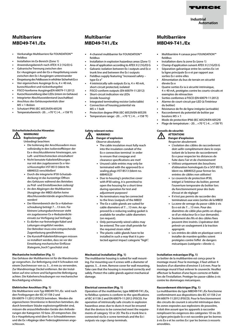
Die Drucktransmitter mit Ex-Zulassung können nur über einen Stecker nach EN 175301-803-A
(IP65) oder einem Rundstecker M12 × 1 (IP67) elektrisch angeschlossen werden. Die Geräte
verfügen über einen analogen Stromausgang (4…20 mA).
Montieren
GEFAHR
Explosionsfähige Atmosphäre
Explosion durch zündfähige Funken!
Bei Einsatz im Ex-Bereich:
Gerät nur montieren und anschließen, wenn keine explosionsfähige Atmosphäre
vorliegt.
ACHTUNG
Unsachgemäße Montage
Geräteschäden
Gerät nicht an einer Stelle montieren, an der hohe Druckimpulse wirken können.
Gerät vor direkter Sonneneinstrahlung schützen.
Geräte mit Ex-Zulassung können in die Grenzwand zwischen Zone 0 und Zone 1 montiert
werden. Dabei muss der Prozessanschluss ausreichend dicht nach EN 60079-26, Abschnitt 4.3
sein (z. B. durch Einhaltung der Schutzart IP67 nach EN 60529).
Durch starke thermische Veränderungen in der Umgebung des Sensors kann es zu einer
Nullpunktverschiebung kommen. Dabei steht der angezeigte Messwert im drucklosen Zustand
nicht auf Null.
Die Geräte können in beliebiger Lage (Ausrichtung) montiert werden. Die Lage des Geräts hat
keinen Einfluss auf die Messgenauigkeit. Das Einsatzmedium muss für Materialien mit Medien-
kontakt zum Drucktransmitter geeignet sein.
Vor der Montage: Prozessdaten mit den Daten des Leistungsschilds vergleichen.
Gerät am Sechskant des Gehäuses festziehen. Das maximale Anzugsdrehmoment beträgt
für G1/2“-Druckanschlüsse 30 Nm, für alle anderen Druckanschlüsse 20 Nm.
DE Kurzbetriebsanleitung
Pressure transmitter PT1000/PT2000
Additional documents
You will find the following supplementary documents online at www.turck.com:
■Data sheet
■Device approvals
For your safety
Intended use
These devices are designed for use only in industrial areas.
The pressure transmitters are suitable for liquids, gases and refrigerants, including ammonia.
The type PT…IX and PT…UX… pressure transmitters are suitable for use in Ex areas. Using
these devices with flammable substances is only permitted if the membranes of the measuring
cells are sufficiently chemically resistant to these substances and resistant to corrosion from
these substances.
The devices must only be used as described in this manual. Any other usage shall be consid-
ered improper and Turck shall not be held liable for any resulting damage.
Obvious misuse
The devices are not considered to be safety components within the scope of the Pressure
Equipment Directive or the Machinery Directive and must not be used as a form of personal
and property protection.
General safety instructions
■The device must only be assembled, installed, operated, parameterized and maintained by
professionally-trained personnel.
■The devices fulfill exclusively the EMC requirements for industrial applications and are not
suitable for use in residential areas.
■Connect the device to a separated extra-low voltage (SELV).
■Only supply the device with restricted energy, in accordance with UL 61010-1, Second
Edition, Chapter 9.3 or LPS in accordance with UL 60950-1 or Class 2 in accordance with UL
1310 or UL 1585.
Explosion protection notes
■When using the device in explosion-protection circuits, the user must have a working knowl-
edge of explosion protection (EN 60079-14, etc.).
■Adhere to national and international regulations on explosion protection.
■Only use the device within the permissible operating and ambient conditions (see technical
data and conditions from the Ex approval).
■Never connect the device to intrinsically safe circuits if it has been previously operated in
non-intrinsically safe circuits.
Product description
The pressure transmitters consist consist of a ceramic measuring cell (PT1000) or a fully welded
measuring cell (PT2000), installed in a stainless steel housing. The product spectrum comprises
devices with a wide range of plugs, protection classes and current and voltage outputs. The
pressure transmitters can be used to measure an absolute pressure or relative pressure of
between -1 and +60 bar (PT1000 series) or a relative pressure of between -1 and +1000 bar
(PT2000 series). The measuring range is factory set.
The pressure transmitter with Ex approval can only be connected to the electrical system via a
connector in accordance with EN 175301-803-A (IP65) or via a round connector M12 × 1 (IP67).
The devices are equipped with an analog current output of 4…20 mA.
Mounting
DANGER
Explosive atmospheres
Explosion due to ignitable sparks!
For use in the Ex area:
Assemble and connect the device only if the atmosphere is not explosive.
ATTENTION
Improper mounting
Damage to device
Do not mount the device in a location that is subject to high pressure pulses.
Protect the device from direct sunlight.
Devices with Ex approval can be mounted in the boundary wall between Zone 0 and Zone 1.
Here, the process connection must be sufficiently thick in accordance with EN 60079-26, Sec-
tion 4.3 (e.g. via compliance with protection class IP67 in accordance with EN 60529).
Strong thermal changes in the environment of the sensor can result in a zero offset. In this case,
in a pressure-free state, the measured value displayed is not null.
The devices may be mounted in any position (arrangement). The position of the device has no
influence on the measurement accuracy. The medium being measured must be suitable for the
parts of the pressure transmitter in contact with the medium.
Before mounting: Compare process data with the data of the nameplate.
Fix the device to the hexagonal of the housing. For G1/2”pressure connections, the maxi-
mum tightening torque is 30 Nm. For all other pressure connections the maximum tighten-
ing torque is 20 Nm.
EN Quick-Start Guide
Transmetteur de pression PT1000/PT2000
Documents complémentaires
Ce document est complété par les documents suivants, disponibles sur notre site web www.
turck.com:
■Fiche technique
■Homologations de l’appareil
Pour votre sécurité
Utilisation correcte
Les appareils sont conçus pour être uniquement utilisés dans le domaine industriel.
Les transmetteurs de pression sont adaptés pour des liquides, des gaz et des fluides frigori-
gènes, y compris l’ammoniac. Les transmetteurs de pression de type PT…IX et PT…UX… sont
adaptés à une utilisation en zone Ex. L’utilisation avec des matières inflammables n’est autorisée
que si les membranes des cellules de mesure sont suffisamment résistantes chimiquement
pour ces matières et sont résistantes à la corrosion.
Les appareils doivent être utilisés conformément aux indications du manuel. Toute autre
utilisation est considérée comme non conforme et Turck décline toute responsabilité en cas de
dommages qui en résulteraient.
Exemples de mauvaises utilisations
Les appareils ne sont pas des composants de sécurité au sens de la directive sur les équipe-
ments sous pression ou de la directive sur les machines et ne peuvent être utilisés à des fins de
protection des personnes ou des biens.
Consignes générales de sécurité
■Seul un personnel qualifié est habilité à monter, installer, utiliser, paramétrer et entretenir
l’appareil.
■Les appareils répondent exclusivement aux exigences de la directive CEM pour le secteur
industriel et ne sont pas destinés à être utilisés dans les zones d’habitation.
■Raccordez l’appareil à une très basse tension de sécurité (TBTS).
■Alimentez l’appareil uniquement avec une énergie limitée, selon la norme UL61010-1,
deuxième édition, chapitre 9.3 ou selon LPS en accord avec la norme UL60950-1 ou selon la
classe2 en accord avec la norme UL1310 ou UL1585.
Remarques sur la protection Ex
■Pour toute utilisation en milieu Ex, l’opérateur doit posséder des connaissances en matière
de protection contre les explosions (EN60079-14, etc.).
■Respectez les directives nationales et internationales en matière de protection contre les
explosions.
■Utilisez l’appareil uniquement dans les conditions ambiantes et de fonctionnement autori-
sées (voir les caractéristiques techniques et les exigences de l’homologationEx).
Description du produit
Les transmetteurs de pression se composent d’une cellule de mesure en céramique (PT1000)
ou une cellule de mesure entièrement soudée (PT2000), installé dans un boîtier en acier inoxy-
dable. Cette catégorie de produits comprend des appareils dotés de prises, indices de protec-
tion et sorties de courant et de tension différents. Les transmetteurs de pression permettent de
mesurer une pression absolue ou relative comprise entre -1 et +60bar (série PT1000) ou une
pression relative comprise entre -1 et +1000bar (série PT2000). La plage de mesure est bien
définie.
Les transmetteurs de pression avec homologation Ex seulement peuvent être raccordés à l’aide
d’un connecteur selon EN175301-803-A (IP65) ou d’un connecteur coaxial M12×1 (IP67). Les
appareils sont equipés d’une sortie de courant analogique de 4 à 20mA.
Montage
DANGER
Atmosphère explosive
Explosion par étincelles inammables!
Utilisation dans la zone Ex:
Montez et raccordez l'appareil uniquement si l'atmosphère n'est pas explosive.
ATTENTION
Montage non conforme
Risque d'endommagement de l'appareil
Ne montez pas l'appareil sur un emplacement où des impulsions de pression élevées
peuvent avoir des conséquences.
Veillez à ne pas exposer directement l'appareil à la lumière du soleil.
Les appareils avec homologation Ex peuvent être montés dans la limite entre la zone0 et la
zone1. Pour cela, le raccordement au processus doit être suffisamment étanche, conformé-
ment à la norme EN60079-26, partie 4.3 (p.ex. en respectant l’indice de protection IP67 selon
EN60529).
De fortes variations thermiques de l’environnement du capteur peuvent entraîner un déplace-
ment du zéro. Dans ce cas, en l’absence de pression, la valeur de mesure affichée n’est pas nulle.
Il est possible de monter les appareils dans n’importe quel sens. La position de l’appareil
n’influe pas sur l’exactitude de la mesure. Le milieu doit être adapté aux matériaux en contact
avec le transmetteur de pression.
Avant le montage: Comparez les données de processus avec celles de la plaque signalé-
tique.
Serrez l’appareil sur le six pans du boîtier. Le couple de serrage maximal est de 30Nm pour
les raccords de pression G1/2» et de 20Nm pour tous les autres.
FR Guide d’utilisation rapide
