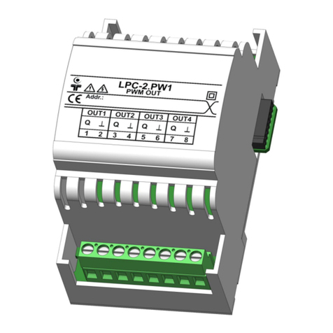
Smarteh LONGO LPC-2 User manual


Other manuals for LONGO LPC-2
3
This manual suits for next models
1
Table of contents
Other Smarteh Controllers manuals
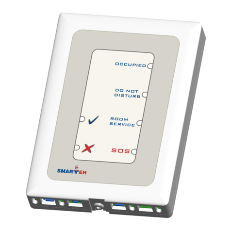
Smarteh
Smarteh LPC-2.ID1 User manual
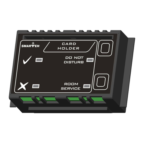
Smarteh
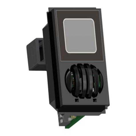
Smarteh LPC-2.ID2V User manual
Smarteh
Smarteh LPC-2.VV1 User manual
Smarteh
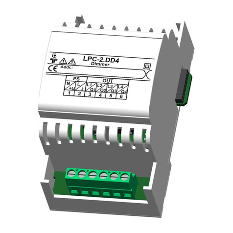
Smarteh LPC-2.DD4 User manual
Smarteh
Smarteh LPC-2.P02V User manual
Smarteh
Smarteh LPC-2.IR2V User manual
Smarteh
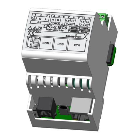
Smarteh LPC-2.MC9 User manual
Smarteh
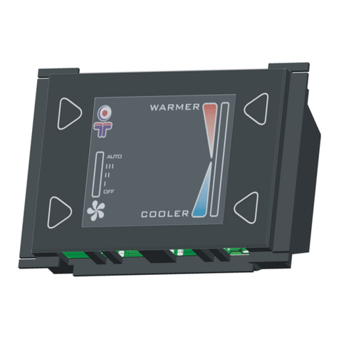
Smarteh LPC-2.DP1 User manual
Smarteh
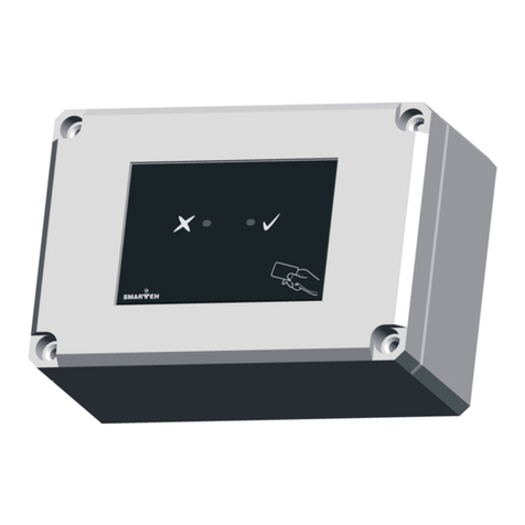
Smarteh LONGO LPC-2.CR2 User manual
Smarteh
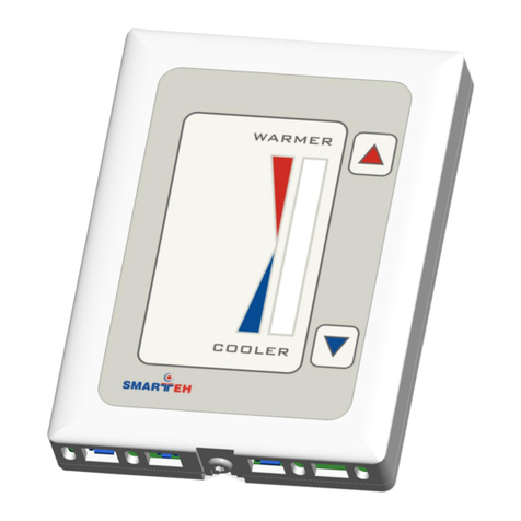
Smarteh LPC-2.CA2M User manual
Smarteh
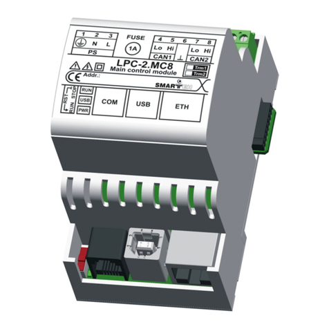
Smarteh LPC-2.P02 User manual
Smarteh
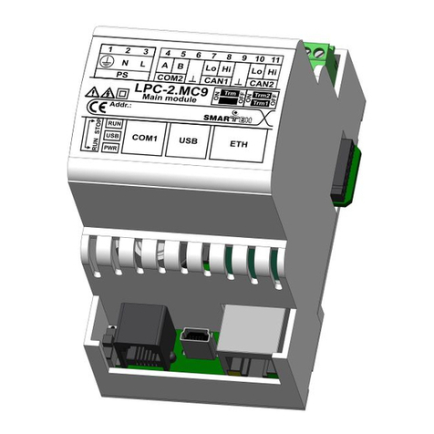
Smarteh LONGO LPC-2 User manual
Smarteh
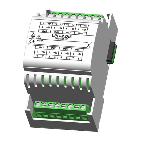
Smarteh LPC-2.MC9 User manual
Smarteh
Smarteh LPC-2.DI5 User manual
Smarteh
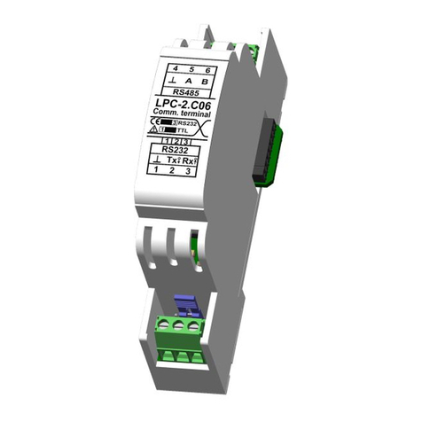
Smarteh LPC-2.C06 User manual
Smarteh
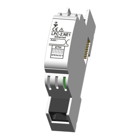
Smarteh LPC-2.NE1 User manual
Smarteh
Smarteh Longo LPC-2.A03 User manual
Smarteh
Smarteh Longo LPC-2.SM6 User manual
Smarteh
Smarteh LPC-2.WT1 User manual
Smarteh
Smarteh LPC-2.CH1 User manual
Popular Controllers manuals by other brands
Mindsets
Mindsets IQ-PRI quick start guide
gefran
gefran ADV200 Series Functions description and parameters list
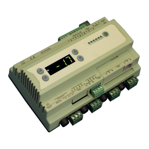
Resource Data Management
Resource Data Management PR0750-TDB Installation & user guide

Titan Controls
Titan Controls Helios 11 instruction manual
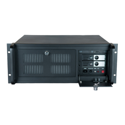
Datapath
Datapath VSN870 user guide
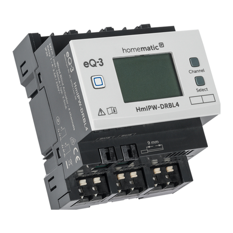
HomeMatic
HomeMatic HmIPW-DRBL4 Installation instructions and operating manual
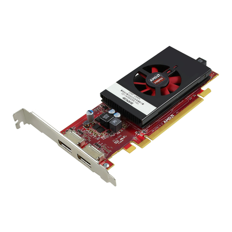
Barco
Barco MXRT-1450 user guide

Promation Engineering
Promation Engineering P1-12VN4 AC Installation & operation manual
AirPatrol Lite
AirPatrol Lite WiFi Version 2 Full manual
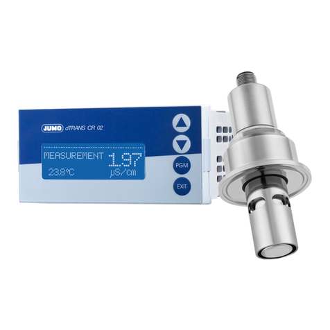
JUMO
JUMO dTRANS CR 02 operating manual
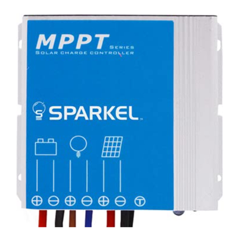
Sparkel
Sparkel Smart-MPPT Series manual

Emerson
Emerson Bettis XTE3000 Maintenance Instruction
