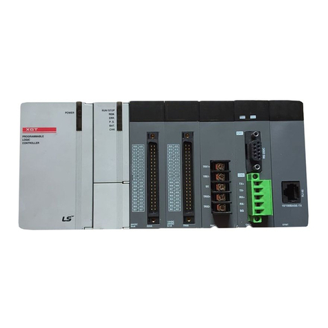
LSIS XGT Series User manual

Right choice for ultimate yield
LSIS strives to maximize customers' profit in gratitude of choosing us for your partner.
Programmable Logic Controller
XGK/I/R Datalog Module
User’s Manual
Read this manual carefully before
installing, wiring, operating, servicing
or inspecting this equipment.
Keep this manual within easy reach
for quick reference.
XGF-DL16A
XGT Series
http://eng.lsis.biz

Safety Instruction
Before using the product …
For your safety and effective operation, please read the safety instructions
thoroughly before using the product.
►Safety Instructions should always be observed in order to prevent accident
or risk with the safe and proper use the product.
►Instructions are separated into “Warning”and “Caution”, and the meaning of
the terms is as follows;
This symbol indicates the possibility of serious injury
or death if some applicable instruction is violated
This symbol indicates the possibility of slight injury
or damage to products if some applicable instruction
is violated
►The marks displayed on the product and in the user’s manual have the
following meanings.
Be careful! Danger may be expected.
Be careful! Electric shock may occur.
►The user’s manual even after read shall be kept available and accessible to
any user of the product.
Warning
Caution

Safety Instruction
Safety Instructions when designing
Please, install protection circuit on the exterior of PLC to protect
the whole control system from any error in external power or PLC
module. Any abnormal output or operation may cause serious problem
in safety of the whole system.
- Install applicable protection unit on the exterior of PLC to protect
the system from physical damage such as emergent stop switch,
protection circuit, the upper/lowest limit switch, forward/reverse
operation interlock circuit, etc.
- If any system error (watch-dog timer error, module installation error,
etc.) is detected during CPU operation in PLC, the whole output is
designed to be turned off and stopped for system safety. However,
in case CPU error if caused on output device itself such as relay or
TR can not be detected, the output may be kept on, which may
cause serious problems. Thus, you are recommended to install an
addition circuit to monitor the output status.
Never connect the overload than rated to the output module nor
allow the output circuit to have a short circuit, which may cause a
fire.
Never let the external power of the output circuit be designed to
be On earlier than PLC power, which may cause abnormal output or
operation.
In case of data exchange between computer or other external
equipment and PLC through communication or any operation of
PLC (e.g. operation mode change), please install interlock in the
sequence program to protect the system from any error. If not, it
may cause abnormal output or operation.
Warning

Safety Instruction
Safety Instructions when designing
I/O signal or communication line shall be wired at least 100mm
away from a high-voltage cable or power line. If not, it may cause
abnormal output or operation.
Caution
Use PLC only in the environment specified in PLC manual or
general standard of data sheet. If not, electric shock, fire, abnormal
operation of the product or flames may be caused.
Before installing the module, be sure PLC power is off. If not,
electric shock or damage on the product may be caused.
Be sure that each module of PLC is correctly secured. If the
product is installed loosely or incorrectly, abnormal operation, error or
dropping may be caused.
Be sure that I/O or extension connecter is correctly secured. If
not, electric shock, fire or abnormal operation may be caused.
If lots of vibration is expected in the installation environment,
don’t let PLC directly vibrated. Electric shock, fire or abnormal
operation may be caused.
Don’t let any metallic foreign materials inside the product, which
may cause electric shock, fire or abnormal operation.
Caution

Safety Instruction
Safety Instructions when wiring
Prior to wiring, be sure that power of PLC and external power is
turned off. If not, electric shock or damage on the product may be
caused.
Before PLC system is powered on, be sure that all the covers of
the terminal are securely closed. If not, electric shock may be caused
Warning
Let the wiring installed correctly after checking the voltage rated
of each product and the arrangement of terminals. If not, fire,
electric shock or abnormal operation may be caused.
Secure the screws of terminals tightly with specified torque when
wiring. If the screws of terminals get loose, short circuit, fire or abnormal
operation may be caused.
Surely use the ground wire of Class 3 for FG terminals, which is
exclusively used for PLC. If the terminals not grounded correctly,
abnormal operation may be caused.
Don’t let any foreign materials such as wiring waste inside the
module while wiring, which may cause fire, damage on the product
or abnormal operation.
Caution

Safety Instruction
Safety Instructions for test-operation or repair
Safety Instructions for waste disposal
Don’t touch the terminal when powered. Electric shock or abnormal
operation may occur.
Prior to cleaning or tightening the terminal screws, let all the
external power off including PLC power. If not, electric shock or
abnormal operation may occur.
Don’t let the battery recharged, disassembled, heated, short or
soldered. Heat, explosion or ignition may cause injuries or fire.
Warning
Don’t remove PCB from the module case nor remodel the module.
Fire, electric shock or abnormal operation may occur.
Prior to installing or disassembling the module, let all the
external power off including PLC power. If not, electric shock or
abnormal operation may occur.
Keep any wireless installations or cell phone at least 30cm away
from PLC. If not, abnormal operation may be caused.
Caution
Product or battery waste shall be processed as industrial waste.
The waste may discharge toxic materials or explode itself.
Caution

Revision History
Revision History
Version Date Remark Chapter
V1.0 ’12.03 First Edition -
V1.1 ’14.11 Added the contents
- Chapter 4 updated the setting sequence 4-2 ~ 4-9
- Chapter 9 added the application example 9-1 ~ 9-7
- Appendix added internal memory information A-2
※The number of User’s manual is indicated right part of the back cover.
ⓒLSIS Co., Ltd 2012 All Rights Reserved.

About User’s Manual
1
CongratulationsonpurchasingPLCof LSIS Co.,Ltd.
Before use, make sure to carefully read and understand the User’s Manual about the functions, performances, installation and
programming of the product you purchased in order for correct use and importantly, let the end user and maintenance
administratortobeprovidedwiththe User’s Manual.
The User’s Manual describes the product. If necessary, you may refer to the following description and order accordingly. In
addition, youmayconnectourwebsite (http://eng.lsis.biz/)anddownloadtheinformationasaPDFfile.
RelevantUser’sManuals
Title
Description
SerialNo.
XG5000User’s Manual
(forXGK,XGB)
XG5000 software user manual describing online function
suchas programming, print, monitoring, debugging by using
XGK,XGBCPU
10310000512
XG5000 User’s Manual
(forXGI,XGR)
XG5000 software user manual describing online function
suchas programming, print,monitoring, debuggingbyusing
XGI,XGRCPU
10310000834
XGK/XGB Instructions &Programming
User’s Manual
User’s manual for programming to explain how to use
instructions thatareusedPLCsystemwithXGK,XGBCPU.
10310000510
XGI/XGRInstructions&Programming
User’s Manual
User’s manual for programming to explain how to use
instructions thatareusedPLCsystemwithXGI,XGRCPU.
10310000833
XGK CPU User’s Manual
(XGK-CPUA/CPUE/CPUH/CPUS/CPUU)
XGK-CPUA/CPUE/CPUH/CPUS/CPUU user manual
describing about XGK CPU module, power module, base,
IO module, specification of extension cable and system
configuration,EMCstandard
10310000820
XGI CPU User’s Manual
(XGI-CPUU)
XGI-CPUU user manual describing about XGK CPU
module, power module, base, IO module, specification of
extensioncable andsystem configuration,EMCstandard
10310000832
XGR redundant series User’s
Manual
XGR-CPUU user manual describing about XGR CPU
module, power module, extension drive, base, IO module,
specification of extension cable and system configuration,
EMCstandard
10310001059
CurrentusermanualofXGF-DL16Ais writtenbasedonthefollowingversion.
RelatedO/S versionlist
Productname
O/S version
XGK-CPUH,CPUS,CPUE,CPUU,CPUU/D
V3.90
XGI-CPUU,CPUH,CPUA,CPUS, CPUE
V3.50
XGR-CPUH/F,CPUH/T
V2.20
XG5000
V3.64

Contents
1
◎
Contents
◎
Chapter 1 Introduction
1.1 Special Feature --------------------------------------------------------------------------------------------------- 1-1
1.2 Introduction of data processing ----------------------------------------------------------------------------------- 1-3
Chapter 2 Product Specification
2.1 General Specifications -------------------------------------------------------------------------------------------- 2-1
2.2 Performance Specifications ---------------------------------------------------------------------------------------- 2-2
2.3 System Configuration ---------------------------------------------------------------------------------------------- 2-3
2.3.1 System Configuration --------------------------------------------------------------------------------- 2-3
2.3.2 Application System -------------------------------------------------------------------------------------- 2-3
2.4 Part Name --------------------------------------------------------------------------------------------- 2-4
2.4.1 Part Name ------------------------------------------------------------------------------------------ 2-4
2.4.2 Contents of LED Display ------------------------------------------------------------------------------------ 2-5
Chapter 3 Installation and Test Operation
3.1 Installation Environment ------------------------------------------------------------------------------------------ 3-1
3.2 Precautions for Handling ------------------------------------------------------------------------------------------ 3-2
Chapter 4 Setting Sequence
4.1 Sequence of Setting the Datalog Module ---------------------------------------------------------------------------- 4-1
4.2 Method to Set Datalog Module ------------------------------------------------------------------------------------- 4-2
Chapter 5 Input/Output Signal of Datalog Module
5.1 Input/Output Signal of Datalog Module ------------------------------------------------------------------------------- 5-1
5.1.1 Input/Output Signal Statement ---------------------------------------------------------------------------------- 5-1
5.1.2 Description of Input/Output Signals ---------------------------------------------------------------------------- 5-2
5.2 File Configuration ----------------------------------------------------------------------------------------------- 5-3
5.3 CSV File Format -------------------------------------------------------------------------------------------------- 5-4
5.3.1 Format Specification of CSV File --------------------------------------------------------------------------- 5-4
5.3.2 Data Saving File ----------------------------------------------------------------------------------------- 5-4

Contents
2
Chapter 6 Data Saving Function
6.1 Saving Data ------------------------------------------------------------------------------------------------------- 6-2
6.2 Data saving --------------------------------------------------------------------------------------------------- 6-3
6.2.1 Data saving method ----------------------------------------------------------------------------------------- 6-3
6.2.2 Scan time data saving -------------------------------------------------------------------------------------- 6-4
6.2.3 Data saving at a task interval--------------------------------------------------------------------------- 6-4
6.3 Saving method ----------------------------------------------------------------------------------------------------- 6-4
6.3.1 Saving designated by the Ladder program ---------------------------------------------------------------------------- 6-4
6.4 Data saving file ------------------------------------------------------------------------------------------------ 6-5
6.4.1 Saving type of data saving file ----------------------------------------------------------------------------- 6-5
6.4.2 Saving method of data saving file ------------------------------------------------------------------------- 6-5
6.4.3 Saving CF Card initialized file ---------------------------------------------------------------------------- 6-5
6.4.4 Inputting I/O parameter ----------------------------------------------------------------------------------- 6-5
Chapter 7 CF Card
7.1 CF card -------------------------------------------------------------------------------------------------------- 7-1
7.2 Name of CF Card Part -------------------------------------------------------------------------------------------- 7-1
7.3 Cautions in Using CF Card --------------------------------------------------------------------------------------- 7-2
7.3.1 CF Card /Folder Name ------------------------------------------------------------------------------------- 7-2
7.3.2 When Disconnecting or Replacing CF Card--------------------------------------------------------------------- 7-2
7.3.3 CF Card Capacity ----------------------------------------------------------------------------------------- 7-2
7.4 Manipulation in Mounting CF Card --------------------------------------------------------------------------------- 7-2
7.5 Manipulation in Disconnect or Replace CF Card ---------------------------------------------------------------------- 7-3
7.6 Lifetime of CF Card ---------------------------------------------------------------------------------------------- 7-4
7.6.1 Calculation of Lifetime ------------------------------------------------------------------------------------ 7-4
7.6.2 Total Writable Size ---------------------------------------------------------------------------------------- 7-4
7.7 Processing Time ---------------------------------------------------------------------------------------------------- 7-4
7.7.1 Processing Time ------------------------------------------------------------------------------------------ 7-4
Chapter 8 USB Memory
8.1 Caution in Using USB Memory --------------------------------------------------------------------------------------- 8-1
8.1.1 USB Memory/Folder Name ------------------------------------------------------------------------------------ 8-1
8.1.2 When Disconnecting or Replacing USB memory ----------------------------------------------------------------- 8-1
8.1.3 USB Memory Backup ---------------------------------------------------------------------------------------- 8-1
8.1.4 Use of USB memory in Vibration Environments ---------------------------------------------------------------- 8-1
8.2 Manipulation to mount USB memory --------------------------------------------------------------------------------- 8-2
8.3 Lifetime of USB Memory --------------------------------------------------------------------------------------------- 8-3
8.3.1 Calculation of Lifetime ------------------------------------------------------------------------------------ 8-3
8.3.2 Total Writable Size ---------------------------------------------------------------------------------------- 8-3
8.4 Processing Time ---------------------------------------------------------------------------------------------------- 8-3
8.4.1 Processing Time ------------------------------------------------------------------------------------------- 8-3
Contents
3
Chapter 9 Application Example
9.1 XGK CPU Application Example --------------------------------------------------------------------------- 9-1
9.1.1 Temperature Data Logging ------------------------------------------------------------------------------ 9-1
9.1.2 Searching Function ------------------------------------------------------------------------------------- 9-3
9.2 XGI/R CPU Application Example --------------------------------------------------------------------------- 9-5
9.2.1 Temperature Data Logging ----------------------------------------------------------------------------- 9-5
9.2.2 Searching Function ------------------------------------------------------------------------------------ 9-7
Chapter 10 Troubleshooting
10.1 Basic troubleshooting procedure ------------------------------------------------------------------------------------ 10-1
10.2 Troubleshooting ----------------------------------------------------------------------------------------------------------------------- 10-2
10.2.1 Response to RUN LED’s blackout ----------------------------------------------------------------------- 10-3
10.2.2 Response when program is not written ----------------------------------------------------------------- 10-4
10.2.3 Troubleshooting Questionnaires ----------------------------------------------------------------------------- 10-5
Appendix
A.1 Dimension ------------------------------------------------------------------------------------------------------- A-1
A.2 Internal Memory Information ---------------------------------------------------------------------------------- A-2

Chapter 1 Introduction
1-1
Chapter 1 Introduction
This user’s manual describes Datalogmodulespecification,sequenceoffunctionaloperationandsavingdata.
If any program example introduced in this user’s manual is used in the actual system, fully review if there is any control problem
withthe system.
Inaddition,incaseofthedatalogmodule,PLC devicedata collectedthroughsimplesettingscanbesavedonCFcard
incorporatedin themodule andduplicated onUSBmemory.
1.1 Special Feature
Specialfeatures of the datalogmodule areas follows:
1) CapabletoeasilysavePLCdevicedatawithoutPC
PLCdevicecanbesavedwithoutusingPC.
Itcansavecostsas wellas itgivesnoneedtoworryaboutPCsystem’s breakdown or cutting of cables.
Thatis, thecollecteddatacanbesavedinaproperfiletypeonCF cardandUSBmemory.
< Figure1.1SystemConfiguration of the DatalogModule>

Chapter 1 Introduction
1-2
2) CapabletosavePLCcontroldatawithoutmissing anychange
Datacanbesavedwheneverscanningisdoneor theycanbesavedat anintervalof severalms(milliseconds).
Itplaysanimportantroleinidentifyingcausesofatroublesinceitdoes notmissinganycontroldatathathasbeensetwhen
savingdata.
<Figure1.2 Datasavingatan Intervalof100ms>
3) Capabletosavealargevolumeof datafile
Long-term data saving isavailablesinceCF cardandUSBmemorywithalargevolumeofupto16GB canbeused.
But,useindustrialCF cardmanufacturedbyTranscend.

Chapter 1 Introduction
1-3
1.2 Introduction of Data Processing
Thedatalogmodule saves devicevalues savedonPLCCPUinaformoffileonCF cardand USBmemory.
Adata saved for a certain period in a file can be saved in a data saving file. Therefore, it is possible to analyze the saved data in
detailsbyusingthis.
Thefollowingfigureshows theflowofpreparingafile.
< Figure1.3IntroductionofDataProcessing>

Chapter 2 Product Specification
2-1
Chapter 2 Product Specification
2.1 General Specifications
Generalspecifications ofXGTseries areasfollows.
No.
Items
Specifications
Relatedstandards
1
Ambient
temperature
0~55C
2
Storage
temperature
25~70C
3
Ambient
humidity
5~95%RH(Non-condensing)
4
Storagehumidity
5~95%RH(Non-condensing)
5
Vibration
resistance
Occasionalvibration
-
Frequency
Acceleration
Amplitude
times
IEC61131-2
10 f 57Hz
0.075mm
10timeseach
directions
(X,YandZ)
57 f 150Hz
9.8m/s2(1G)
Continuousvibration
Frequency
Acceleration
Amplitude
10 f 57Hz
0.035mm
57 f 150Hz
4.9m/s2(0.5G)
6
Shock
resistance
Peakacceleration:147m/s2(15G)
Duration:11ms
Half-sine,3timeseachdirectionpereachaxis
IEC61131-2
7
Noiseresistance
Squarewave
Impulsenoise
1,500V
LSISstandard
Electrostatic
discharge
4kV(Contactdischarge)
IEC61131-2
IEC61000-4-2
Radiated
electromagneticfield
noise
80~1,000MHz, 10V/m
IEC61131-2,
IEC61000-4-3
Fasttransient/bust
noise
Segmen
t
Powersupply
module
Digital/analoginput/output
communicationinterface
IEC61131-2
IEC61000-4-4
Voltage
2kV
1kV
8
Environment
Freefromcorrosivegassesandexcessivedust
9
Altitude
Upto2,000ms
10
Pollutiondegree
2orless
11
Cooling
Air-cooling
[Table2.1]GeneralSpecifications
Note
1) IEC (InternationalElectrotechnicalCommission):
Aninternationalnongovernmentalorganizationwhichpromotesinternationallycooperatedstandardizationin
Electric/electronicfield publishesinternationalstandards andmanages applicableestimationsystemrelated with.
2)Pollutiondegree:
An index indicating pollution degree of the operating environment which decides insulation performance of the devices. For instance, Pollution
degree 2 indicates the state generally that only non-conductive pollution occurs. However, this state contains temporary conduction due to dew
produced.

Chapter 2 Product Specification
2-2
2.2 Performance Specifications
Item
Specification
CF Card
Voltageofpowersupply
3.3V± 5%
CardType
CF200I(Transcend’s IndustrialCF card)
CompatibilityCapacity
1,2,4,8,16Gbyte
Number ofmountablecards
1
Caution
UseonlyindustrialCF cardsmanufacturedbyTranscend
USBMemory
Voltageofpowersupply
5.0V± 5%
MemoryType
USB2.0(Hostfunction)
CompatibilityCapacity
1,2,4,8,16Gbyte(Pleaseuse USBcapacityaboveCFcardcapacity)
Saving Method
AutoSavingthrough PnPfunction
(ActivationofPnPautoduplication:whenUSBismounted,whenpowerissuppliedagain)
Number ofmountablememories
1(UnavailabletosupportUSBextensioncables)
DataType
BOOL
0 or 1
BYTE
00~ FF
WORD
0000 ~ FFFF
DWORD
00000000 ~ FFFFFFFF
LWORD
00000000 00000000~FFFFFFFFFFFFFFFF
SINT
-128~ 127
INT
-32,768~ 32,767
DINT
-2,147,483,648~2,147,483,647
LINT
-576,460,752,303,423,488~576,460,752,303,423,487
USINT
0~255
UINT
0~65,535
UDINT
0~4,294,967,295
ULINT
0~1,152,921,504,606,846,975
REAL
-3.402823466e+038~-1.175494351e-038or0
or 1.175494351e-038~3.402823466e+038
LREAL
-1.7976931348623157e+308~-2.2250738585072014e-308 or0or
2.2250738585072014e-308~1.7976931348623157e+308
STRING
Fixedletters(Maximum8letters)
Data Saving
Number ofSettings
Maximum8
Number ofData
Maximum32
Saving Kind
Savedby theladder program
FileType
CSVfile(Extension:csv)
Number ofSavingFiles
Total800(when using16GbyteCF memory)
Saving Speed
ProcessingScore(word)
4
16
64
256
1024
ProcessingSpeed(ms)
1
4
10
30
120
Timeto
InitializeCF
card
Capacity(Gbyte)
1
2
4
8
16
Time(s)
10
20
40
60
120
CollectionInterval
1~9999999ms(Inconsecutivesaving)
In/outputOccupationScore
32points1slot(Input22points,output10points)
Clock
SynchronizedatPLCCPUtimewheneveritisscanned
DC5VInternalConsumption Current
0.53A
ExternalSize
98(H)[mm]×27(W)[mm]×90(D)[mm]
Weight
0.13kg

Chapter 2 Product Specification
2-3
2.3 System Configuration
Itdescribesthe system configurationofthe Datalogmodule.
2.3.1 System Configuration
Thefollowingshowsconfigurationofthe systemwhenusingthe Datalogmodule.
< Figure2.1ConfigurationoftheDatalogmoduleSystem >
2.3.2ApplicationSystem
1) CPUmodule that can bemounted
Productname
OSversion
XGK-CPUH,CPUS,CPUE,CPUU,CPUU/D
V3.90
XGI-CPUU,CPUH,CPUA,CPUS, CPUE
V3.50
XGR-CPUH/F,CPUH/T
V2.20
XG5000
V3.64

Chapter 2 Product Specification
2-4
2.4 Part Name
Eachpartof theDatalogmodule has thefollowing name.
2.4.1 Part Name
< Figure2.2PartNameof theDatalogModule>
Name
Description
①
Productname
Displaythenameof theDatalog module’s name(XGF-DL16A)
②
DisplayLED
DisplayLEDaccordingtothe statusofthesystem
③
USBMemorySlot
SlottomountUSBmemorytothe Datalogmodule
④
CF CardSlot
SlottomountCF cardto theDatalogmodule
⑤
EJECTButton
ButtontodisconnectCFcardfrom the Datalogmodule

Chapter 2 Product Specification
2-5
2.4.2 Contents of LED Display
< Figure2.3LED Silk ofthe Datalogmodule>
Name
Description
RUN
OntheDatalogmodulerunsnormally
I/F
Flashingsending/receivingbetweentheDatalogmodule andthe CPU module is normally
processed.
RDY
OntheDatalogmoduleis completelyreadyforrunning.
CF RD
Flashing CF card’s data is transferring to USB memory
CF WR
FlashingtheDatalogmodulewritesdatatoCFcard
CF ERR
Onanerrortakesplacefrom CFcardactions
CF CONN
OnconnectingCFcard
USBRD
FlashingUSBmemoryisfirstmountedandinitialized
USBWR
FlashingCFcardwritesdatatoUSBmemory
USBERR
On error takes place from USB memory’s actions
USBCONN
OnmountingUSB memory
UEND,CEND
Ondisconnectionisavailable since datasavingis completedonCF cardandUSBmemory
Ex)Whenconnectingtothemoduleafterformatting CF card:RUN(On),I/F(On/Off repeated),CFCONN(On),CFWR(On)
Wheninitializingafter connectingUSBmemory: RUN(On),I/F(On/Off repeated),USBCONN(On),USBRD(On)
Whenprocessing/completing backupafterconnectingUSBmemory:RUN(On),I/F(On/Off repeated),USBCONN(On),
CFCONN(On),CFRD(On),USBWR(On) →
CFRD(Off)and USBWR(Off)
.

Chapter 3 Installation and Test Operation
3-1
Chapter 3 Installation and Test Operation
3.1 Installation Environment
This product is of high reliance regardless of installation environment. However, for the sake of reliance and stability of the
system,pleasepayattentiontothose precautions describedbelow.
(1) EnvironmentalConditions
(a) To be installedonthecontrol panelwaterproof and dustproof.
(b) Nocontinuousimpact orvibrationshallbe expected.
(c) Not tobeexposedtothe directsunlight.
(d) No dewshallbecausedbyrapidtemperaturechange.
(e) Ambienttemperatureshallbekept0-55℃.
(2) Installation Work
(a) No wiringwasteis allowedinsidePLCwhenwiringor drilling screwholes.
(b) Tobeinstalledon agood locationtoworkon.
(c) Don’t let it installed on the same panel as a high-voltagedeviceison.
(d) Letitkeptatleast50㎜awayfrom duct ornear-bymodule.
(e) Tobegroundedinanagreeable placefreefromnoise.
(f) Mount Ferrite Corewhenconnectingpower cablesaftercompleting
Other manuals for XGT Series
21
This manual suits for next models
1
Table of contents
Other LSIS Controllers manuals

LSIS
LSIS MASTER-K200S Owner's manual

LSIS
LSIS XGT Series User manual

LSIS
LSIS XEC-DN32H/DC User manual

LSIS
LSIS sv-ip5a User manual

LSIS
LSIS XEC-DR32H User manual

LSIS
LSIS XGT Series User manual

LSIS
LSIS XP10BKA/DC User manual

LSIS
LSIS XGL-CH2A User manual

LSIS
LSIS XBM-DN16S User manual

LSIS
LSIS XGT Series User manual

LSIS
LSIS XGT Series User manual

LSIS
LSIS XGT Series User manual

LSIS
LSIS SV-iS7 series User manual

LSIS
LSIS XGL-EFMT User manual

LSIS
LSIS XEC-DN32U User manual

LSIS
LSIS S100 Series Programming manual

LSIS
LSIS Master-K K200S User manual

LSIS
LSIS XBC-DN32U User manual

LSIS
LSIS XGT Series User manual

LSIS
LSIS XGT Series User manual