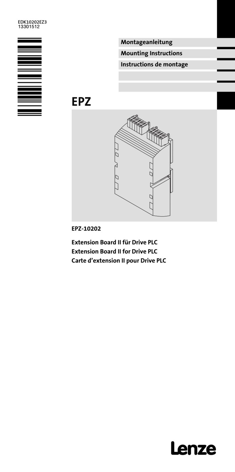
Lenze II EPZ-10202 User manual

Extension Board II EPZ-10202
für Drive PLC
EDK10202EZ3 4.1
l
Lenze Drive Systems GmbH, Postfach 10 13 52, D-31763 Hameln
(+49) 5154 82-0, Fax Service: (+49) 5154 82-1112
Diese Anleitung
yenthält die wichtigsten Technischen Daten, beschreibt die Installation, die
Handhabung und die Inbetriebnahme des Extension Board II.
yist nur gültig
- für das Extension Board II mit der Typenbezeichnung EPZ-10202
- zusammen mit der Montageanleitung der DrivePLC.
Beschreibung
Das Extension Board II erweitert die Drive PLC um 14 digitale Eingänge und 8 digitale
Ausgänge.
Einsatzbereich
Einsetzbar mit der Drive PLC Typ EPL-10200-EI
Zubehör
Beliegend befindet/befinden sich
- zwei Stiftleisten, jeweils 2 x 13 pol. (bereits montiert bei EPL-10202-EI)
- zwei Klemmleisten, jeweils 6pol. für digitale Eingänge (I9 ... I14 und I15 ... I20)
- eine Klemmleiste 6pol. für digitale Ausgänge (05 ... 010)
- eine Klemmleiste 6pol. für Ausgangsspannung (+024, ⊥24),
digitale Eingänge (I21, I22), digitale Ausgänge (011, 012)
Allgemeine Daten und Einsatzbedingungen
Konformität CE Niederspannungsrichtlinie (73/23/EWG)
Approbationen UL 508C Underwriter Laboratories (File-No. E132659)
Power Conversion Equipment
DC-Versorgungsspannung Spannung extern +18 VDC -0 % ... +30 VDC +0 %
D
C
V
e
r
s
o
r
g
u
n
g
s
s
p
a
n
n
u
n
g
Strom max. 8 A
(bei max. Belastung aller Ausgänge)
Klimatische Bedingungen Klasse 3K3 nach EN 50178
(ohne Betauung, mittlere relative Feuchte 85 %)
Temperaturbereiche Transport -25 °C ... +70 °C
T
e
m
p
e
r
a
t
u
r
b
e
r
e
i
c
h
e
Lagerung -25 °C ... +60 °C
Betrieb 0 °C ... +40 °C ohne Leistungsreduzierung
+40 °C ... +55 °C mit Leistungsreduzierung
Leistungsreduzierung der Ausgangsströme bei t
U
>+40°C:2,5%/K
Rüttelfestigkeit Beschleunigungsfest bis 0.7 g
Zulässige Einbaulage in der Drive PLC auf Steckplatz für Extension Board
Isolationsspannung zur
Bezugserde/PE
50 V AC
Schutzart IP 20
Digitale Eingänge Pegel LOW (0 V ... +4 V)
HIGH (+13 V ... +30 V)
Eingangsstrom max. 8 mA bei 24 V
Digitale Ausgänge Pegel LOW (0 V ... +4 V)
HIGH (+13 V ... +30 V)
Belastbarkeit max. 1 A pro Ausgang
Abmessungen Höhe 145 mm (incl. Klemmleisten)
A
b
m
e
s
s
u
n
g
e
n
Breite 72 mm
Tiefe 35 mm
EDK10202EZ3
00465733
05/03
Show/Hide Bookmarks

Mechanische Installation
EDK10202EZ3 4.1
l
-2-
Während der Installation Versorgungsspannung der Drive PLC abschalten!
cSchutzkappe
von der Drive PLC [1a]
entfernen und aufbewahren.
A
1a
dStiftleisten
auf das Extension
Board [1b] einsetzen.
B
1b
eExtensionBoard[1b]indie
Drive PLC [1a] einsetzen.
1a
1b
fKlemmen des Extension Board belegen.
PES: HF-Schirmabschluß durch
PE-Anbindung
PES
PES
Show/Hide Bookmarks

Klemmenbelegung
EDK10202EZ3 4.1
l
-3-
Klemmen - Übersicht
X1
X2
X3
X4
Klemmen Belegung
X1 Digitale Ausgänge (X1/O5 ... X1/010)
X2 Digitale Eingänge (X2/I21, X2/I22)
X
2
Digitale Ausgänge (X2/O11, X2/O12)
DC-Versorgungsspannung (X2/⊥24, X2/+O24)
X3 Digitale Eingänge (X3/I15 ... X3/I20)
X4 Digitale Eingänge (X4/I9 ... X4/I14)
Show/Hide Bookmarks

Klemmenbelegung
EDK10202EZ3 4.1
l
-4-
Erforderliche Verbindung Mögliche Verbindung
Drive PLC
Extension Board II cNot-Aus
dVerbraucher eGeber
Klemme Signaltyp Funktion Technische Daten Anmerkung
X1/O5 Digitale
A
ä
LOW (0 V ... +4 V)
H
I
G
H
(
1
3
V
3
0
V
)
...
g
t
a
e
Ausgänge
O
(
0
)
HIGH (+13 V ... +30 V)
B
e
l
a
s
t
b
a
r
k
e
i
t
:
m
a
x
1
A
X1/O10 Belastba
r
k
eit: max. 1
A
X2/I21 Digitale
Eingänge
LOW (0 V ... +4 V)
HIGH (+13 V ... +30 V)
X2/I22
E
i
n
g
ä
n
g
e
H
I
G
H
(
+
1
3
V
...
+
3
0
V
)
Eingangsstrom:
max. 8 mA bei 24 V
X2/+O24 -DC-Versorgungsspannung 18 VDC ... 30 VDC Geschaltet über
Not-Aus an der
Drive PLC
X2/⊥24 -GND, Bezugspotential
X2/O11 Digitale
A
u
s
g
ä
n
g
e
LOW (0 V ... +4 V)
H
I
G
H
(
+
1
3
V
+
3
0
V
)
X2/O12
A
usgänge HIGH (+13
V
... +30
V
)
Belastbarkeit: max. 1 A
X3/I15 Digitale
E
i
ä
LOW (0 V ... +4 V)
G
...
D
i
g
i
t
a
l
e
Eingänge
L
O
W
(
0
V
.
.
.
+
4
V
)
HIGH (+13 V ... +30 V)
E
i
n
g
a
n
g
s
s
t
r
o
m
:
X3/I20 Eingangsst
r
om:
m
a
x.
8
m
A
b
e
i24
V
X4/I9
m
a
x
.
8
m
A
b
e
i
2
4
V
...
X4/I14
Hinweis!
yAchten Sie auf eine ausreichende Dimensionierung der DC-Spannungsversorgung, wenn Sie
Verbraucher an die digitalen Ausgänge anschließen.
yDas Extension Board ausschließlich separat versorgen. Die interne Versorgung über die Drive PLC ist
nicht zulässig.
Show/Hide Bookmarks

Inbetriebnahme
EDK10202EZ3 4.1
l
-5-
Überprüfen Sie vor dem Einschalten der Versorgungsspannung die
gesamte Verdrahtung auf Vollständigkeit und Kurzschluß.
Einschalten:
1. Versorgungsspannung für Drive PLC und Extension Board einschalten
- Das Extension Board wird automatisch erkannt.
2. Drive PLC Developer Studio (DDS)-Projekt in die Drive PLC laden
- Siehe Dokumentation zu DDS und zu Drive PLC.
3. Die zusätzlichen Eingänge und Ausgänge stehen jetzt für die Steuerung zur
Verfügung. Die Steuerung ist betriebsbereit.
Hinweis zu Drive PLC mit Softwarestand ab Version 6.1:
Die Drive PLC erkennt automatisch
yfehlende Verbindungen zum Extension Board.
yein nicht zum Anwenderprogramm kompatibles Extension Board.
yein fehlendes Extension Board.
Hinweis zu Drive PLC mit Softwarestand vor Version 6.1:
Die Drive PLC erkennt nicht automatisch
yfehlende Verbindungen zum Extension Board.
yein nicht zum Anwenderprogramm kompatibles Extension Board.
yein fehlendes Extension Board.
Fehlende Verbindungen, nicht kompatible oder fehlende Extension Boards können im
Anwenderprogramm undefinierte Aktionen auslösen, die die Maschine / Anlage
gefährden können.
Stellen Sie deshalb vor Inbetriebnahme einer Drive PLC mit Extension Board sicher, daß
ydas Extension Board immer mit beiden 26poligen Stiftleisten mit der Drive PLC
verbunden ist (siehe Montageanleitung Extension Board, Kapitel “Mechanische
Installation”, Stiftleisten ).
yder Typ des Extension Board zum Anwenderprogramm kompatibel ist.
Lenze stellt Ihnen Funktionsblöcke zur Verfügung, die Sie in Ihr
Anwendungsprogramm für die Drive PLC laden können. Die Drive PLC
erkennt dadurch fehlende Verbindungen beziehungsweise nicht
kompatible Extension Boards und gibt daraufhin eine Fehlermeldung aus.
Diese Funktionsblöcke können Sie von der Lenze Homepage
herunterladen:
www.Lenze.de (Menü “Service” →“Downloads” →“PLC Produkte”).
Show/Hide Bookmarks

Extension Board II EPZ-10202
for Drive PLC
EDK10202EZ3 4.1
l
Lenze Drive Systems GmbH, Postfach 10 13 52, D-31763 Hameln
(+49) 5154 82-0, Fax Service: (+49) 5154 82-1112
These Instructions
ycontain the most important technical data, describe the installation, handling and
commissioning of the extension board II.
yare only valid
- for the extension board II with the type designation EPZ-10202
- together with the Mounting Instructions for the Drive PLC.
Description
Theextension board II extends theDrivePLCby 14 digitalinputs and eight digital outputs.
Scope of application
Applicable together with the Drive PLC type EPL-10200-EI
Accessories
Items supplied
- two plug connectors, 2 x 13 pole each (already assembled at EPL-10202-EI)
- two terminal strips, six-pole each for digital inputs (I9 ... I14 und I15 ... I20)
- one 6-pole terminal strip for digital inputs (05 ... 010)
- one 6-pol terminal strip for output voltage (+024, ⊥24),
digital inputs (I21, I22), digital outputs (011, 012)
General data and application conditions
Conformity CE Low-Voltage Directive (73/23/EEC)
Approvals UL 508C Underwriter Laboratories (File-No. E132659)
Power Conversion Equipment
DC supply voltage Voltage external +18 VDC -0 % ... +30 VDC +0 %
D
C
s
u
p
p
l
y
v
o
l
t
a
g
e
Current max. 8 A
(at max. load of all outputs)
Climatic conditions Class 3K3 to EN 50178
(without condensation, average relative humidity 85 %)
Temperature range Transport -25°C...+70°C
T
e
m
p
e
r
a
t
u
r
e
r
a
n
g
e
storage -25°C...+60°C
Operation 0 °C ... +40 °C without power derating
+40 °C ... +55 °C with power derating
Power derating of output currents for t
a
>+40°C:2.5%/K
Vibration resistance Resistant to acceleration up to 0.7 g
Permissible mounting
positions
in the Drive PLC on a plug-in-station for extension board
Insulation voltage to PE 50 V AC
Enclosure IP 20
Digital inputs Level LOW (0 V ... +4 V)
HIGH (+13 V ... +30 V)
Input current max.8mAat24V
Digital outputs Level LOW (0 V ... +4 V)
HIGH (+13 V ... +30 V)
Load capacity max. 1 A per output
Dimensions Height 145 mm (incl. terminal strips)
D
i
m
e
n
s
i
o
n
s
Width 72 mm
Depth 35 mm
EDK10202EZ3
00465733
05/03
Show/Hide Bookmarks

Mechanical installation
EDK10202EZ3 4.1
l
-2-
During installation switch off the voltage supply for the Drive PLC!
cRemove the protection cover
from the
Drive PLC [1a] and keep it.
A
1a
dPlug the plug connectors
onto the
Extension Board [1b].
B
1b
eConnect the Extension Board [1b] to the
Drive PLC [1a].
1a
1b
fAssign the terminals of the Extension
Board.
PES: HF shield termination by PE
connection
PES
PES
Show/Hide Bookmarks

Terminal assignment
EDK10202EZ3 4.1
l
-3-
Terminals - overview
X1
X2
X3
X4
terminals Assignment
X1 Digital outputs (X1/O5 ... X1/010)
X2 Digital inputs (X2/I21, X2/I22)
X
2
Digital outputs (X2/O11, X2/O12)
DC supply voltage (X2/ ⊥24, X2/+O24)
X3 Digital inputs (X3/I15 ... X3/I20)
X4 Digital inputs (X4/I9 ... X4/I14)
Show/Hide Bookmarks

Terminal assignment
EDK10202EZ3 4.1
l
-4-
Connection required Possible connection
Drive PLC
Extension board II cEmergency off
dLoad eEncoder
Terminal Signal type Function Technical data Remarks
X1/O5 Digital LOW (0 V ... +4 V)
H
I
G
H
(
1
3
V
3
0
V
)
...
g
t
a
outputs
O
(
0
)
HIGH (+13 V ... +30 V)
L
o
a
d
c
a
p
a
c
i
t
y
:
m
a
x
1
A
X1/O10 Load capacity: max. 1
A
X2/I21 Digital
inputs
LOW (0 V ... +4 V)
HIGH (+13 V ... +30 V)
X2/I22
i
n
p
u
t
s
H
I
G
H
(
+
1
3
V
...
+
3
0
V
)
Input current: max. 8
mA at 24 V
X2/+O24 -DC supply voltage 18 VDC ... 30 VDC Connected via
emergency off at the
Drive PLC
X2/ ⊥24 -GND, reference potential
X2/O11 Digital
o
u
t
p
u
t
s
LOW (0 V ... +4 V)
H
I
G
H
(
+
1
3
V
+
3
0
V
)
X2/O12 outputs HIGH (+13
V
... +30
V
)
Load capacity: max. 1 A
X3/I15 Digital
i
LOW (0 V ... +4 V)
H
I
G
H
(
1
3
V
3
0
V
)
...
g
t
a
inputs
O
(
0
)
HIGH (+13 V ... +30 V)
I
n
p
u
t
c
u
r
r
e
n
t
:
m
a
x
8
X3/I20 Input cu
r
r
ent: max. 8
m
A
at 24
V
X4/I9
m
A
a
t
2
4
V
...
X4/I14
Note!
yEnsure a sufficient dimensioning of the DC voltage supply, if the loads are connected to the digital
outputs.
yThe extension board must exclusively be supplied separately. The internal supply via the Drive PLC is
not permissible.
Show/Hide Bookmarks

Commissioning
EDK10202EZ3 4.1
l
-5-
Before switching on the supply voltage, check the entire wiring
concerning completeness and short circuit.
Switching on:
4. Switch on the supply voltage for Drive PLC and extension board
- Theextension board is detected automatically.
5. Load Drive PLC Developer Studio (DDS)project in the Drive PLC
- See documention for DDS and Drive PLC.
6. The additional inputs and outputs arenow available forthe control. The control is
ready for operation.
Note on Drive PLC with software version as of version 6.1:
The Drive PLC detects automatically
ymissing connections to the extension board.
yan extension board which is not compatible with theuser program.
ya missing extension board.
Note on Drive PLC with software version earlier than version 6.1:
The Drive PLC does not detect automatically
ymissing connections to the extension board.
yan extension board which is not compatible with theuser program.
ya missing extension board.
Missing connections, incompatibility or missing extension boards can result in undefined
actions which can endanger the machine/system.
Therefore it is absolutely necessary to ensure that
yyou always use two 26-pole plug connectors to connect the extension board with
the Drive PLC (see Mounting Instructions for the Extension Board, chapter
“Mechanical installation”, plug connectors ).
ythe extension board type matches the user program.
Lenzeprovides function blocks which can be loaded into the user program
fortheDrivePLC.WiththesefunctionblockstheDrivePLCdetectsmissing
connections and incompatible extension boards and indicates error
messages.
The function blocks can be downloaded from the Lenze homepage:
www.Lenze.de (menu “Service” →“Downloads” →“PLC Produkte”).
Show/Hide Bookmarks

Carte d’extension II EPZ-10202
pour Drive PLC
EDK10202EZ3 4.1
l
Lenze Drive Systems GmbH, Postfach 10 13 52, D-31763 Hameln
(+49) 5154 82-0, Fax Service: (+49) 5154 82-1112
Le présent fascicule
ycontient les principales caractéristiques techniques de la carte d’extension II et
décrit son installation, sa manipulation et sa mise en service.
yn’est valable que
- pour la carte d’extension II de type EPZ-10202,
- conjointement avec les instructions de montage du Drive PLC.
Description
La carte d’extension II permet une extension de 14 entrées numériques et 8 sorties
numériques du Drive PLC.
Domaine d’utilisation
Utilisation possible avec les Drive PLC type EPL-10200-EI
Accessoires
L’emballage comprend les composants suivants :
- 2 connecteurs à broches (2x 13 broches chacun)(déjàmontés pour
EPL-10202-EI),
- deux borniers à 6 bornes pour les entrées numériques (I9 ... I14 et I15 ... I20).
- un bornier à 6 bornes pour les sorties numériques (05 ... 010),
- un bornier à 6 bornes pour la tension de sortie (+024, ⊥24),
les entrées numériques (I21, I22), les sorties numériques (011, 012).
Caractéristiques générales et conditions d’utilisation
Conformité CE Directive Basse Tension (73/23/CEE)
Homologations UL 508C Underwriter Laboratories (File-No. E132659)
Power Conversion Equipment
Alimentation CC Tension +18 VCC -0 % ... +30 VCC +0 % externe
A
l
i
m
e
n
t
a
t
i
o
n
C
C
Courant 8Amaxi
(avec charge maxi sur toutes les sorties)
Humidité admissible Classe 3K3 selon EN 50178
(sans condensation, humidité relative moyenne 85 %)
Plages de température Transport -25°C...+70°C
P
l
a
g
e
s
d
e
t
e
m
p
é
r
a
t
u
r
e
Stockage -25°C...+60°C
Fonctionnement 0 °C ... +40 °C sans réduction de puissance
+40 °C ... +55 °C avec réduction de puissance
Réduction de puissance des courants de sortie pour t
a
>+40°C:2,5%/K
Résistance aux chocs Résistance à l’accélération jusqu’à 0,7 g
Position de montage
admissible
A l’intérieur du Drive PLC, dans l’emplacement prévu pour la carte
d’extension
Tension d’isolement potentiel
de terre/PE
50 V CA
Indice de protection IP 20
Entrées numériques Niveau BAS (0 V ... +4 V)
HAUT (+13 V ... +30 V)
Courant
d’entrée
8mAmaxipour24V
Sorties numériques Niveau BAS (0 V ... +4 V)
HAUT (+13 V ... +30 V)
Charge
admissible
1Amaxiparsortie
Encombrements Hauteur 145 mm (borniers compris)
E
n
c
o
m
b
r
e
m
e
n
t
s
Largeur 72 mm
Profondeur 35 mm
EDK10202EZ3
00465733
05/03
Show/Hide Bookmarks

Installation mécanique
EDK10202EZ3 4.1
l
-2-
Pendant l’installation, couper la tension d’alimentation du Drive PLC !
cEnlever le capot de protection
du
Drive PLC [1a] (le conserver
précieusement).
A
1a
dEnficher les connecteurs à broches
dans la carte d’extension [1b].
B
1b
eEnficher la carte d’extension [1b] dans le
Drive PLC [1a].
1a
1b
fAffecter les bornes de la carte
d’extension.
PES : terminaison blindage HF par
raccordement PE
PES
PES
Show/Hide Bookmarks

Affectation des bornes
EDK10202EZ3 4.1
l
-3-
Borniers - Vue d’ensemble
X1
X2
X3
X4
Bornier Affectation
X1 Sorties numériques (X1/O5 ... X1/010)
X2 Entrées numériques (X2/I21, X2/I22)
X
2
Sorties numériques (X2/O11, X2/O12)
Alimentation courant continu (X2/ ⊥24, X2/+O24)
X3 Entrées numériques (X3/I15 ... X3/I20)
X4 Entrées numériques (X4/I9 ... X4/I14)
Show/Hide Bookmarks

Affectation des bornes
EDK10202EZ3 4.1
l
-4-
Liaison impérative Liaison possible
Drive PLC
Carte d’extension II cArrêt d’urgence
dRécepteur eAlimentation
Borne Type de
signal
Fonction Spécifications
techniques
Nota
X1/O5 Sorties
é
i
BAS (0 V ... +4 V)
H
A
U
T
(
1
3
V
3
0
V
)
... numériques
(
)
HAUT (+13 V ... +30 V)
C
h
a
r
g
e
m
a
x
i
X1/O10
C
h
a
r
ge max
i
admissible : 1 A
X2/I21 Entrées
numériques
BAS (0 V ... +4 V)
HAUT (+13 V ... +30 V)
X2/I22
n
u
m
é
r
i
q
u
e
s
H
A
U
T
(
+
1
3
V
...
+
3
0
V
)
Courant d’entrée :
8mAmaxipour24V
X2/+O24 -Alimentation courant
continu
18 VCC ... 30 VCC Coupée via arrêt
d’urgence sur le Drive PLC
X2/ ⊥24 -GND, potentiel de
référence
X2/O11 Sorties
numériques
BAS (0 V ... +4 V)
HAUT (+13 V ... +30 V)
X2/O12
n
u
m
é
r
i
q
u
e
s
H
A
U
T
(
+
1
3
V
...
+
3
0
V
)
Charge maxi
admissible : 1 A
X3/I15 Entrées
é
i
BAS (0 V ... +4 V)
H
A
U
T
(
1
3
V
3
0
V
)
...
t
é
e
s
numériques
S
(
0
)
HAUT (+13 V ... +30 V)
C
o
u
r
a
n
t
d
’
e
n
t
r
é
e
:
X3/I20 Cou
r
ant d’ent
r
ée :
8
m
A
m
a
xi
p
o
u
r
24
V
X4/I9
8
m
A
m
a
x
i
p
o
u
r
2
4
V
...
X4/I14
Remarque importante !
yLors du raccordement des récepteurs aux sorties numériques, assurer un dimensionnement suffisant
de l’alimentation courant continu.
yPour la carte d’extension, prévoir impérativement une alimentation externe. L’alimentation interne via
Drive PLC n’est pas admise.
Show/Hide Bookmarks

Mise en service
EDK10202EZ3 4.1
l
-5-
Avant la mise sous tension, vérifier le câblage dans son intégralité et les
court-circuits éventuels.
Mise en service
1. Mettrele Drive PLC et lacarte d’extension sous tension.
- La carte d’extension est détectée automatiquement.
2. Charger le projet Drive PLC Developer Studio (DDS)dans le Drive PLC.
- Voir documentation concernant DDS et Drive PLC.
3. Les entrées et sorties supplémentaires peuvent maintenant être activées. La
commandeestprêteàfonctionner.
Remarque importante concernant le Drive PLC avec version logicielle supérieure ou
égale à la version 6.1 :
Le Drive PLC reconnaît automatiquement
ysi l’appareil n’est pas relié à la carte d’extension,
ysi la carte d’extension n’est pas compatible avec le programme utilisateur,
ysi la carte d’extension est débranchée.
Remarque importante concernant le Drive PLC avec version logicielle antérieure à 6.1 :
Le Drive PLC ne reconnaît pas automatiquement
ysi l’appareil n’est pas relié à la carte d’extension,
ysi la carte d’extension n’est pas compatible avec le programme utilisateur,
ysi la carte d’extension est débranchée.
Une mauvaise liaison, une carte d’extension non compatible ou manquante peuvent
provoquer des actions indéfinies dans le programme utilisateur, qui peuvent mettre en
danger la machine, l’installation ou les personnes.
Avant la mise en service d’un Drive PLC avec la carte d’extension, s’assurer
impérativement que
yla carte d’extension est toujours reliée au Drive PLC via les deux connecteurs
26 broches (voir Instructions de montage carte d’extension, chapitre “Installation
mécanique”, connecteurs à broches ).
yle type de la carte d’extension est compatible avec le programme utilisateur.
Lenzemet à votre dispositiondes blocs fonction pour DrivePLC que vous
pouvez charger dans votre programme utilisateur. Le Drive PLC est alors
en mesure de détecter l’absence de liaison ou la non-compatibilité de la
carte d’extension et affiche un message défaut.
Ces blocs fonction peuvent être téléchargés à partir de la page d’accueil
Lenze :
www.Lenze.fr (menu “Service” →“Downloads” →“PLC Produkte”).
Show/Hide Bookmarks
Table of contents
Languages:
Other Lenze Computer Hardware manuals
Popular Computer Hardware manuals by other brands

Ista
Ista AMF2.0 Operator's manual

ekwb
ekwb EK-Quantum Momentum ROG Crosshair VIII Hero user guide

Freescale Semiconductor
Freescale Semiconductor e200z3 Reference manual

Wheatstone
Wheatstone FM-25 Technical manual

Digital Voice Systems
Digital Voice Systems AMBE-3000 HDK user manual

Alphacool
Alphacool GPX-N 1080-M17 instruction manual