Installation instructions for JC50322 3W Emergency Self Test Exit Box
Emergency Range
a
Important warranty information
This product is supported by a 2-year standard warranty which will extend to 3 years if registered within the first year of purc
hase.
(2 year on batteries). Please register at jcc.co.uk/warranty - Terms and conditions apply.
The installer will be asked to provide the following information, which is detailed on a label attached to the luminaire’s chas
sis:
JCC Lighting Products Ltd. Lux Park, Chichester Business Park, City Fields Way, Tangmere, Chichester, West Sussex, PO20 2FT
Technical Support: +44(0)1243 838986 Customer Services: +44(0)1243 838999
BS EN ISO9001 - 2015 - Registered Firm Certificate No. GB 1552
V4_Sept_2022_RS
Warnings & Cautions
• To avoid electric shock, serious injury or property damage, isolate
power before installing, removing or servicing the product.
• It is recommended that luminaires are installed by a qualied
electrician to ensure the installation complies with the local current
wiring regulations.
• Any broken or damaged parts should be replaced as soon as possible.
JCC will not accept responsibility for claims arising from sub-standard
installations; which will void the warranty.
• This product is designed for connection to a 220-240V~ 50/60Hz.
• It may be necessary to upgrade your MCBs to allow for increased
inrush current.
• This product is suitable for indoor use only.
• It is recommended that the ambient room temperature should not
exceed 30°C.
• Read instructions and check that you have all of the tools and
accessories required to complete the installation correctly. Isolate power
supply before starting installation.
• Do not carry out insulation tests with the product connected to
the circuit.
INSTALLATION ENGLISH
RoHS
Compliant IP20 jcc.co.uk
Colour temp: 6000K Ra: 72
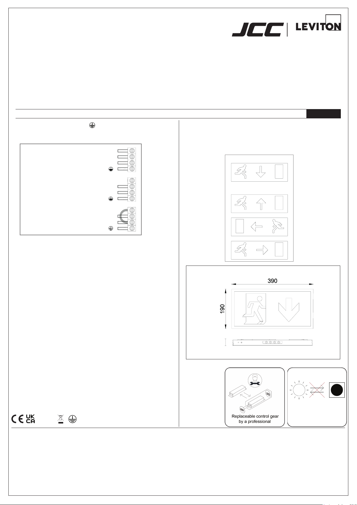
Neutral: Blue
(linked)Sw Live:Brown
Usw/Live: Black
Earth:
Neutral: Blue
Usw/Live: Black
Earth:
Neutral: Blue
Sw Live: (do not use)
Usw/Live: Black
Earth:
Maintained(3M)
+Light on 24/7
+Emergency
(keep link)
Maintained(3M)
+Light on/off switched
+Emergency
(remove link)
Non-maintained(3NM)
+Light off 24/7
+Emergency
Installation procedure
1. To open, remove the screw on the end of the tting and partially slide
the front cover out of the body, then ease out the top from the body.
2. Disconnect the LED lead on the front cover from the circuit board.
3. Use the back plate as a template to mark for holes to secure the
tting, ensuring suitable xings are used for the intended location.
4. Connect the mains input supply as indicated in gure 1 for the
required operation.
5. Connect the emergency battery leads to the circuit board (right hand
side of the circuit board).
6. Reconnect the LED lead on the front cover (next to the battery
connection).
7. Ret the body to the base by aligning the bottom of the front cover,
then clip the top in place. Slide the front into postion and ret the
retaining screw.
8. Switch on mains supply and test for operation (allow 24hrs for
batteries to charge).
9. Familiarise yourself with the enclosed emergency ttings test record
sheet and ensure it is completed as required.
Function test
1. With mains supply and green indicator light on, press the Test Button
to check function.
2. Green indicator light will go off and the tting will operate in
emergency mode.
3. Release the button and the indicator light will come on and the tting
will then return to previous operation.
3W 220-240V~ 50/60Hz - Class I
Down legend supplied
JC50329- not supplied
(Left/right/up legend - set of 3)
Legends
To change the legend, remove the front as described in points 1 and 2 above.
Remove the light guide board from the front cover.
Replace the legend with the required legend. Ret the light guide board and
ret to base as per points 6 and 7.
Prole & Dimensions
All dimensions in millimetres
Non-replaceable light source
LED LED


