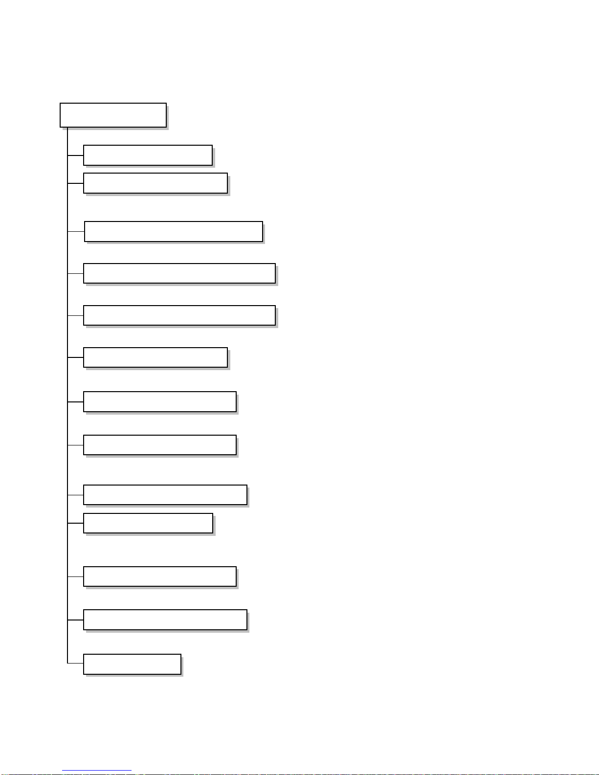
LG LP-10091CL/XL User manual

Package Air Conditioner
SERVICE MANUAL
MODEL: LP-10091CL/XL
LP-15091CL/XL
LP-20091CL/XL

1. Preface............................................................................................... 3
2. Dimensions........................................................................................ 7
3. Refrigerant Cycle Diagram............................................................... 8
4. Wiring Diagram ................................................................................. 9
5. Operation Details............................................................................ 17
6 Installation....................................................................................... 20
7. 3-Way Valve ..................................................................................... 33
8. Troubleshooting Guide................................................................... 40
9. Electronic Control Device .............................................................. 53
10. Schematic Diagram......................................................................... 55
11. Exploded View & Replacement Parts List .................................... 56
– 2 –
CONTENTS

This service manual provides various service information, containing the mechanical and electrical parts and etc.
This package air conditioner was manufactured and assembled under the strict quality control system.
The refrigerant is charged at the factory. Be sure to read the safety precautions prior to servicing the unit.
1.1 Safety Precautions
1. When servicing the unit, set the main SWITCH to OFF and remove the POWER SUPPLY cables.
2. Observe the original lead dress. If a short circuit is found, replace all parts which have been overheated or dam-
aged by the short circuit.
3. After servicing the unit, make an insulation resistance test to protect the customer from being exposed to shock
hazards.
1.2 Features
1. Design for cooling
2. Super energy efficiency
3. Removable air filter
4. 3 minute delay circuit
5. Child Lock function (LP-10091CL/XL, 15091CL/XL)
7. Micom Control (LP-10091CL/XL, 15091CL/XL)
8. 7 hour timer (LP-10091CL/XL, 15091CL/XL)
– 3 –
1. PREFACE

– 4 –
POWER SUPPLY Ø, V, Hz
COOLING CAPACITY Btu/hr
ELECTRIC HEATER KW
CAPACITY
POWER INPUT COOLING
W
E/ HEATER
W
RUNNING COOLING W
CURRENT E/ HEATER W
MODEL
MAKER
TYPE
COMPRESSOR
COOLING Btu/hr
CAPACITY
INPUT (KW)
LRA A
NOISE LEVEL
INDOOR
dB(A)
OUTDOOR
dB(A)
AIR
INDOOR CMM
CIRCULATION
OUTDOOR
CMM
REFRIGERANT (R-22) kg
HEAT
INDOOR
R/C/FPI
EXCHANGER
OUTDOOR
R/C/FPI
FAN
INDOOR
TYPE
OUTDOOR
TYPE
ROOM TEMPERATURE CONTROL
WIDTH
INDOOR
HEIGHT
mm
DEPTH
WIDTH
OUTDOOR
HEIGHT
mm
DEPTH
NET WEIGHT
INDOOR kg
OUTDOOR kg
CONNECTIONS
LIQUID inch(
mm)
GAS inch(
mm)
ITEMS UNIT
MODEL
LP-10091CL LP-15091CL LP-15091XLLP-10091XL LP-20091CL LP-20091XL
3,220/380, 60 3,220/380, 60 3,220/380, 60
100,000 150,000 200,000
-20-30-40
13,000 13,000 18,500 18,500 24,500 24,500
- 20,000 - 30,000 - 40,000
35.4/21 35.4/21 53.5/31 53.5/31 71/43 71/43
- 53/35 - 78/46 - 106/61
QR12M2-ES8 QR90K2-ES8 QR12M2-ES8
COPELAND COPELAND COPELAND
RECIPRO RECIPRO RECIPRO
115,000 91,100 115,000
12,660 9.59 12,660
213/123 191/110 213/123
60 63 65
62 65 68
89 130 150
150 150 X 2 150 X 2
6.5 8.0 X 2 7.8 X 2
3/ 33/ 17 4/ 28/ 15 4/ 28/ 15
2/ 36/ 17 2/ 34/ 17 2/ 36/ 17
SIRCCO
PROPELLER
MICOM MANUAL
1,050 1,558 1,558
1,860 1,920 1,920
495 700 700
1,245 1,320 1,245
930 990 930
650 650 650
137 155 200 223 200 234
180 170 x 2 180 x 2
1/2 5/8 5/8
11/10 1 11/10
D
I
M
E
N
S
I
O
N
S
1.3 Product Specifications

– 5 –
1.4 Functions
Indoor Unit
Power Switch ON/OFF
Operation Mode Control
Sensing the room temperature
Sensing the pipe temperature
Controlling the room temperature
Starting Current Control
Timer Delay Safety Control
Indoor Fan Speed Control
Operation Indication lamps
Temperature Setting
Airflow Direction Control
Room temperature Display
Timer Control
• Cooling, Fan, Soft dry, Auto operation ⇒"CL" series Model
• Cooling, Heater, Fan, Soft dry, Auto operation ⇒"XL" series Model
• Room temperature sensor (Thermistor)
• Pipe temperature sensor (Thermistor) ⇒LP-10091CL/XL
• Maintains the room temperature in accordance with the setting temperature.
• Indoor fan is delayed for 3 seconds at the starting.
• Restarting is inhibited for approx. 3 minutes.
• Duct, High, Low ⇒LP-10091CL/XL
• High, Low
⇒
LP-15091CL/XL • High
⇒
LP-20091CL/XL
• Up : up to 30°C
• Down : down to 16°C
• Airflow direction Manual control
• Low, 10° ~ 35°C, Hi (LP-10091CL/XL, 15091CL/XL)
• Off Timer (1, 2, 3....7 hour) (LP-10091CL/XL, 15091CL/XL)

– 6 –
Outdoor Unit
Outdoor Fan Speed Control
• One speed
• Discharge pressure sensor (High Pressure Switch)
• Suction pressure sensor (Low Pressure Switch)
Sensing Discharge Pressure For Compressor
Sensing Suchion Pressure for Compressor

2.1 LP-10091CL/XL
2.2 LP-15091CL/XL
2-3 LP-20091CL/XL
– 7 –
2. DIMENSIONS

•
Cooling Cycle
– 8 –
3. REFRIGERANT CYCLE DIAGRAM
INDOOR UNIT
LIQUID SIDE
CAPILLARY
TUBE
HEAT
EXCHANGER
ACCUMULATOR MUFFLER
COMPRESSOR
HEAT
EXCHANGER
3-WAY VALVE
GAS SIDE
3-WAY VALVE
OUTDOOR UNIT

4.1 LP-10091CL
• INDOOR UNIT
–9 –
4. WIRING DIAGRAM
ROOMTH
EVA TH
Tmo
THERMISTOR FOR INDOOR TEMP.
THERMISTOR FOR EVA TEMP.
TERMINAL BLOCK(OUTDOOR)
FMi
Ci INDOOR FAN MOTOR
CAPACITOR FOR FAN(INDOOR) RY4
Tmi RELAY FOR COMP.
TERMINAL BLOCK(INDOOR)
P/No.:3854AP2687J
BL
BK
BR
OR
RD
NOTE
SUB PCB ASM
MAIN PCB ASM
Tmi
INDOOR OUTDOOR
FIELD WIRING
6
5
4
3
2
1Tmo
6
5
4
3
2
1
RY3
DISPLAY
PCB ASM
ROOM
TH
EVA
TH
Ci
BR OR
CN1
CONNECT TO CONTACT
"R", "T" OF OUTDOOR
TERMINAL BLOCK "A"(1ø,220V)
CN2
YL
BL
RD
BK
WH
CN3
RY4
BK
BL
RD
YL
FMi
RY2
RY1 FUSE
(10A)
:
:
:
:
:
BLUE
BLACK
BROWN
ORANGE
RED
WH
YL
GN
GN/YL
:
:
:
:
WHITE
YELLOW
GREEN
GREEN/YELLOW
NOTICE
1. Basic wiring is 3ø,3W,220V,60Hz.
2. For changing the running
voltage to 380V, please change
the wiring by the next steps
1st) Remove the "a" wires from
the 'R' of the terminal block 'A'
and connect the wire to the
'N' of the terminal block 'A'.
2nd) Remove the "b" wire from the
'2' of 52C and connect the wire
to the 'N' of the terminal block 'A'.
3rd) Change the compressor
wires like an example.
4rd) For setting the E.O.C.R current
FIELD WIRING
380V WIRING
220V WIRING
TERMINAL
BLOCK 'A'
3ø3W
220V 60Hz
POWER SUPPLY
3ø4W
380V 60Hz
POWER SUPPLY
Co1
FMo1 FMo2
COMP
UZ
VWXY
Co2
BK
WH
BK TmiTmo
1
2
3
4
5
6
1
2
3
4
5
6
BK
BK
RD
WH
1
2
3
4
5
6
31
B
A
32
L1 L2 Tb Ta
YL BR BK
OR YL BR BK
OR
Tc
OR
BK
WH FUSE(5A)
FUSE(5A)RD WH
BK
RD
BL
BK
BK
51C
63L
BL
CH
WH
RD
RD
OR
52C
b
a
R S T N
BL
BK
BR
FMo1,2
Co1,2 OUTDOOR FAN MOTOR
RUN CAPACITOR FOR FAN(OUTDOOR)
63L
CH
LOW PRESSURE SWITCH
CRANKCASE HEATER
51C
52C EOCR(COMP.)
MAGNETIC CONTACTOR Tmo
Tmi
P/NO ; 3854AP2687K
TERMINAL BLOCK(OUTDOOR)
TERMINAL BLOCK(INDOOR)
BLUE
BLACK
BROWN
:
:
:
OR
RD
WH
ORANGE
RED
WHITE
:
:
:
YL
GN
GN/YL
YELLOW
GREEN
GREEN/YELLOW
:
:
:
NOTE
Power supply
3ø,220V,60Hz
3ø,380V,60Hz
Current(A)
55
40
Time(sec.)
5
5
3ø,3 wires,220V.
UXY
ZXY
Z
V
W
UV
W
3ø,4 wires,380V.
OUTDOOR INDOOR
• OUTDOOR UNIT (LP-10091CL/XL)

–10 –
4.2 LP-10091XL
• INDOOR UNIT
1.The basic wiring of this product is 3Ø,220V
2. If you want to change the runnning voltage
to 380V, change the wiring of electric heater
and outdoor unit.
EH
Ci
ELECTRIC HEATER
CAPACITOR FOR FAN(INDOOR)
FMi
Tmi
INDOOR FAN MOTOR
TERMINAL BLOCK(INDOOR)
POWER SUPPLY
3Ø,220V,60Hz
(3Ø,380V,60Hz)
EH
ROOM
TH
EVA
TH
FMi
Tmi
6
5
4
3
2
1
THERMAL FUSE
THERMAL FUSE
CONNECT TO
OUTDOOR UNIT
RD
CN1
BR OR
BK
BL
RD
YL
DISPLAY
PCB ASM
CN2
CN3
FUSE
(10A)
RY3
RY2
RY1 BK
RDRD 26S1
26S2
RD
RD
BK
BK
YL CONNECT TO CONTACT
"R","N" OF OUTDOOR
TERMINAL BLOCK "Tmo1"
(1Ø, 220V, 60Hz)
NOTE
BL
BK
BR
OR
BLUE
BLAKC
BROWN
ORANGE
:
:
:
:
RD
WH
YL
GN/YL
RED
WHITE
YELLOW
GREEN/YELLOW
:
:
:
:
BL
BK
Ci
RY3
RY6
BK
BK
BK
MAIN PCB ASM
SUB PCB ASM
WH
BK
RD
WH
BK
P/No.:3854AP2687P
26S1,2
RY6 RY3
BIMETAL SWITCH FOR HEATER
RELAY FOR HEATER RELAY FOR COMP.
ELECTRIC HEATER WIRING DIAGRAM P/No,:3854AP2687Q
3ø, 220V 3ø, 380V
3ø, 220V 3ø, 380V
Thermal Fuse
(144˚C,16A,4EA)
Thermal Fuse
(144˚C,16A,4EA)
Thermal Fuse
(144˚C,16A,4EA)
Thermal Fuse
(144˚C,16A,4EA)
1. Basic wiring is 3ø,220V
2. For changing the running voltage to 380V,
please change the electric heater wires like an example.
3.The cross-sectional area of conductors for power supply
must be over 14.0 mm2.
• ELECTRIC HEATER

–11 –
4.3 LP-15091CL
• INDOOR UNIT
P/NO: 3854A20026A
NOTE
TD
Ci1,2
FMi1,2
Tmi THi
Ry4
5 SECOND DELAY TIMER
CAPACITOR(INDOOR)
WIRING DIAGRAM
FMi1 BR
RY3
RY2
RY1
FUSE
(250V/20A)
SUB PCB ASM
YL
BLBK OR BLBK OR
Ci1 BR
CN1
CN2
CN3
RY4
RD
RD
BL
BL
YL
TD
Tmi
6
5
4
3
2
1
WH
BK
RD
CONNECT TO
OUTDOOR UNIT #1
CONNECT TO
OUTDOOR UNIT #2
CONNECT TO CONTACT
"R","N" OF OUTDOOR #1
TERMINAL BLOCK "A"
WH
BK
3
2
1
DISPLAY
PCB ASM
BK
MAIN PCB ASM
BK
YL Ci2 THI
FMi2
INDOOR FAN MOTOR
TERMINAL BLOCK(INDOOR)
THERMISTOR FOR INDOOR TEMP.
RELAY FOR COMP.
BL
BK
BR
OR
RD
BLUE
BLACK
BROWN
ORANGE
RED
:
:
:
:
:
WH
YL
GN
GN/YL
WHITE
YELLOW
GREEN
GREEN/YELLOW
:
:
:
:
( Caution )
1. Basic wiring is 3ø,4wires,380V.
2. For changing the running voltage to 220V.
please change the wiring by the next steps
1st) Remove the "a" wires from the "N" of
Tmo1(Outdoor unit #1,2),and connect the
wire to the "R" of Tmo1(Outdoor unit #1,2)
2nd) Remove the "b"wire fromTmo1(Outdoor
unit #1,2), and connect the wire to the
"1" of 52C
3rd) Change the compressor
wires like an example.
UXY
V
3ø,4 wires,380V.
Power supply
3ø,220V,60Hz
3ø,380V,60Hz
Current(A)
35
24.2
Time(sec.)
5
5
3ø,3 wires,220V.
W
ZUXY
V
W
Z
3. For setting the E.O.C.R current
4. Check list before test run
1st) Reconfirm the wiring of compressor
and motor of indoor unit
2nd) Fasten the screw of "Tmo1" one more.
NOTE
CH
CO1,2
F1,2
FMo1,2
51C
Tmi
Tmo1,2
52C
63H
63L
CRANKCASE HEATER
CAPACITOR FOR FAN
FUSE
OUTDOOR FAN MOTOR
E.O.C.R FOR COMPRESSOR
TERMINAL BLOCK(INDOOR)
TERMINAL BLOCK(OUTDOOR)
MAGNATIC CONTACTOR FOR COMP.
HIGH PRESSURE SWITCH
LOW PRESSURE SWITCH
NOTE
BL
BK
BR
OR
GN/YL
:
:
:
:
:
BLUE
BLACK
BROWN
ORANGE
GREEN/YELLOW
RD
WH
YL
GN
:
:
:
:
RED
WHITE
YELLOW
GREEN
FMo1 FMo2 FMo1 FMo2
3ø,4WIRES
380V 60Hz
POWER SUPPLY
Tmo1 OR
YL BR OR BK YL BR OR BK
RD RD
BK
WH
WH F2
F1
BK
13531
24632
B
ABK
TO "Tmi 1,2" OF
INDOOR UNIT
RD WH
BK BK BL
RD
RDWHBK
COMPRESSOR
L1L2
BK
BK
BK BK
WH
RD
WH
WH
UVWXYZ
Tb Ta
Tc
Co1
OUTDOOR #1 OUTDOOR #2
b
a
Co2
52C
63H
51C Tmo2
CONNECT TO
INDOOR UNIT
1
2
3
4
5
6
63L
3ø,3WIRES
220V 60Hz
POWER SUPPLY
RSTN Tmo1 OR
YL BR OR BK YL BR OR BK
RD RD
BK
WH
WH F2
F1
BK
13531
24632
B
ABK RD WH
BK BK BL
RD
RDWHBK
COMPRESSOR
L1L2
BK
BK
BK
WH
WH
CH
BK
BK
CH
BK
BK UVWXYZ
Tb Ta
Tc
Co1
b
a
Co2
52C
63H
51C Tmo2
To"4"of Tmi
(Indoor unit)
1
2
3
4
5
6
63L
RSTN
OUTDOOR ELECTRIC CIRCUIT
P/NO: 3854A20026B
• OUTDOOR UNIT

–12 –
4.4 LP-15091XL
• INDOOR UNIT
P/NO: 3854A20026E
NOTE
TD
Ci1,2
FMi1,2
Tmi THi
RY1,2,3
5 SECOND DELAY TIMER
CAPACITOR(INDOOR)
WIRING DIAGRAM
INDOOR FAN MOTOR
TERMINAL BLOCK(INDOOR)
THERMISTOR FOR INDOOR TEMP.
RELAY FOR Fmi1,2 Ry4
Ry5 RELAY FOR COMP.
RELAY FOR HEATER
BL
BK
BR
OR
BLUE
BLACK
BROWN
ORANGE
:
:
:
:
RD
WH
YL
GN/YL
RED
WHITE
YELLOW
GREEN/YELLOW
:
:
:
:
1.The basic wiring of this product is 3ø,220V
2. If you want to change the running voltage to 380V
change the wiring of electric heater and outdoor unit
3.The cross-sectional area of conductors for power supply(electric heater)
must be over 38mm2
POWER SUPPLY
3ø,220V,60Hz
(3ø,380V,60Hz)
CONNECT TO
OUTDOOR UNIT #1
CONNECT TO
OUTDOOR UNIT #2
CONNECT TO CONTACT
"R","N" OF Tmo1 (OUTDOOR #1)
(1ø, 220V)
BK
BK
RD
YL
CN3
CN2
RY5
TD
RD
RD
BR
YL
BK ORBL BK ORBL
RY3
RY2
RY1
FUSE
(250V/20A)
BR
YL
WH
BK
RD
WH
BK
3
2
1
RY4
CN1
DISPLAY
PCB ASM
BL
BK
SUB PCB ASM
Ci2
FMi2FMi1 Ci1
THi
BK
6
5
4
3
2
1
BL
Tmi
MAIN PCB ASM
R
S
T
BK
BR BL 4
3
2
1
52H1
52H2
WH
RD
BK
BL BR
EH
RD RD
THERMAL PROTECTOR
THERMAL FUSE
6
5
4101112
THERMAL FUSE
THERMAL FUSE
EH
THERMAL FUSE
3789
2
1
THERMAL FUSE
THERMAL FUSE
THERMAL PROTECTOR
RD
1 2 3
WH
RD
Field Wiring
( Caution )
1. Basic wiring is 3ø,3wires,220V.
2. For changing the running voltage to 380V.
please change the wiring by the next steps
1st) Remove the "a" wires from the "R" of
Tmo1(Outdoor unit #1,2),and connect the
wire to the "N" of Tmo1(Outdoor unit #1,2).
2nd) Remove the "b"wire from "1" of 52C
(Outdoor unit #1,2), and connect the wire
to "N" of Tmo1
3rd) Change the compressor
wires like an example.
UXY
V
W
ZUXY
V
W
Z
Power supply
3ø,220V,60Hz
3ø,380V,60Hz
Current(A)
35
24.2
Time(sec.)
5
5
3. For setting the E.O.C.R current
4. Check list before test run
1st) Reconfirm the wiring of compressor
and motor of indoor unit
2nd) Fasten the screw of "Tmo1" one more.
NOTE
CH
CO1,2
F1,2
FMo1,2
51C
Tmi
Tmo1,2
52C
63H
63L
CRANKCASE HEATER
CAPACITOR FOR FAN
FUSE
OUTDOOR FAN MOTOR
E.O.C.R FOR COMPRESSOR
TERMINAL BLOCK(INDOOR)
TERMINAL BLOCK(OUTDOOR)
MAGNATIC CONTACTOR FOR COMP.
HIGH PRESSURE SWITCH
LOW PRESSURE SWITCH
NOTE
BL
BK
BR
OR
GN/YL
:
:
:
:
:
BLUE
BLACK
BROWN
ORANGE
GREEN/YELLOW
RD
WH
YL
GN
:
:
:
:
RED
WHITE
YELLOW
GREEN
OUTDOOR #1
FMo1 FMo2 FMo1 FMo2
OUTDOOR #2
OUTDOOR ELECTRIC CIRCUIT
P/NO: 3854A20026F
3ø,3 wires,220V. 3ø,4 wires,380V.
3ø,4WIRES
380V 60Hz
POWER SUPPLY
Tmo1 OR
YL BR OR BK YL BR OR BK
RD RD
BK
WH
WH F2
F1
BK BK
13531
246 32
B
A
TO "Tmi 1,2" OF
INDOOR UNIT
RD WH
BK BK BL
RD
RDWHBK
COMPRESSOR
L1L2
BK
BK
BK BK
WH
RD
WH
WH
UVWXYZ
Tb Ta
Tc
Co1
b
a
Co2
52C
63H
51C Tmo2
CONNECT TO
INDOOR UNIT
1
2
3
4
5
6
63L
3ø,3WIRES
220V 60Hz
POWER SUPPLY
RSTN
CH BK
BK
To"4"of Tmi
(Indoor unit)
Tmo1 OR
YL BR OR BK YL BR OR BK
RD RD
BK
WH
WH F2
F1
BK BK
13531
246 32
B
ARD WH
BK BK BL
RD
RDWHBK
COMPRESSOR
L1L2
BK
BK
BK
WH
WH
UVWXY
Tb Ta
Tc
Co1
b
a
Co2
52C
63H
51C Tmo2
1
2
3
4
5
6
63L
RSTN
CH BK
BK
4th) Change the electric heater wires.
• OUTDOOR UNIT

–13 –
4.5 LP-20091CL
• INDOOR UNIT
P/NO: 3854A20026C
NOTE
NOTE
Power supply
3ø,220V,60Hz
3ø,380V,60Hz
Current(A)
7
5
Time(sec.)
5
5
RD
BL
BK
WH
GY
CS
FMi
GL1
GL2
TH
Tmi
23H,L
52Fi
CN
TD
MODE SELECT SWITCH
INDOOR FAN MOTOR
LOW COOL OPERATION LAMP
HIGH COOL OPERATION LAMP
E.O.C.R FOR FMi
TERMINAL BLOCK(INDOOR)
THERMOSTAT
MAGNATIC CONTACTOR FOR FMi
CONNECTOR(9P)
5 SEC. DELAY TIEMR
RED
BLUE
BLACK
WHITE
GRAY
:
:
:
:
:
BR
VT
GN
OR
GN/YL
FIELD WIRING
CONNECT TO OUTDOOR #1
TERMINAL BLOCK 'Tmo2'
CONNECT TO OUTDOOR #2
TERMINAL BLOCK 'Tmo2'
CONNECT TO CONTACT 'R','S','T' OF
OUTDOOR #2 TERMINAL BLOCK 'Tmo1'
BROWN
VIOLET
GREEN
ORANGE
GREEN/YELLOW
:
:
:
:
:
3ø,4 wires,380V. 3ø,3 wires,220V.
1(U)1(U)
6(Y)
2(V)
4(Z)
3(W)
5(X)
2(V)
3(W)
4(Z)
5(X)
6(Y)
1
2
3
4
1
2
3
4
INDOOR ELECTRIC CIRCUIT
CS
GN
RD BR
23L
23H
CN
BK
WH
WH
BK
BR
246 A
135 BVTWH
GN
WH
BL
WH
YL
GN
12345678910
BL BK GY RD GY
TD
Tmi
52Fi
WH
WH
GY
GL1 GL2
BK
FMi
TH
1
L1 L2 Tb Ta
Tc
CT CT
23654
1234
WH WH
YL
1
24 6
32
1
65
4
VT
8
( Caution )
1. Basic wiring is 3ø,4wires,380V.
2. For changing the running voltage to 220V,
please change the wiring by the next steps
1st) Change the motor(Indoor unit) wires
like below
2nd) For setting the E.O.C.R current
4
4 1567
567

–14 –
P/NO: 3854A20026D
OUTDOOR ELECTRIC CIRCUIT
OUTDOOR UNIT#1
OUTDOOR UNIT#2
W
Power supply
3ø,220V,60Hz
3ø,380V,60Hz
Current(A)
55
40
Time(sec.)
5
5
Power supply
3ø,220V,60Hz
3ø,380V,60Hz
Current(A)
7
5
Time(sec.)
5
5
( Caution )
1. Basic wiring is 3ø,4wires,380V.
2. For changing the running voltage to 220V,
please change the wiring by the next steps
1st) Remove the "a" wires from the "N" of
Tmo1(Outdoor unit #1), and connect the
wire to the "R" ofTmo1(Outdoor unit #1).
2nd) Remove the "b"wire fromTmo1(Outdoor
unit #1,2), and connect the wire to the
"1" of 52C
3rd) Change the compressor
wires like an example.
4th) Change the motor(Indoor Unit) wires
like below
3. Remove F1,F2 of Outdoor unit #2.
4. For setting the E.O.C.R current
1st) E.O.C.R for compressor
2nd) E.O.C.R for motor(Indoor unit)
5. Check list before test run
1st) Reconfirm the wiring of compressor
and motor of indoor unit
2nd) Fasten the screw of "Tmo1" one more.
3ø,4 wires,380V.
UXY
Z
VUXY
Z
V
W
3ø,3 wires,220V.
3ø,4 wires,380V. 3ø,3 wires,220V.
NOTE
NOTE
RD
BL
BK
WH
RED
BLUE
BLACK
WHITE
:
:
:
:
BR
GN
OR
GN/YL
FIELD WIRING
BK
BK
L1 L2
CT CT
Tb Ta
Tc
BK
BK
WH
BK
RD RD BK
TO 'Tmi' OF INDOOR UNIT
1234
TO 'Tmi' OF INDOOR UNIT
15674
WH WH RD
RD
RD
RD 3 MIN.
DELAY
P.C.B
YL
BL
RD
BK
BK
CH
CH
U
COMPRESSOR
VWXYZ
WHBK
RD
WH
RSTN
RD
RD
WH BL
BL (1st)
220V 24V
(2nd)
ab
OR
Tmo1
CO1 CO2
3ø,3WIRES
220V 60Hz
POWER SUPPLY
FMo
1
52C
51C
63L 63H
Tmo2
12345678910
F2 F1 TRANS
FMo
2
3ø,4WIRES
380V 60Hz
POWER SUPPLY
BK
BK
L1 L2
CT CT
Tb Ta
Tc
BK
BK
WH
RD
BK
RD BK
WH WH RD
RD
RD
RD 3 MIN.
DELAY
P.C.B
YL
BL
RD
BK
BK
CH
CH
U
COMPRESSOR
VWXYZ
WHBK
RD
WH
RSTN
RD
RD
WH BL
BL (1st)
220V 24V
(2nd)
b
OR 135 A
B
246
15
16
135 A
B
246
15
16
CO1 CO2
TO '52Fi' OF
INDOOR UNIT
FMo
1
52C
51C
63L 63H
Tmo2
12345678910
F2 F1 TRANS
FMo
2
BROWN
GREEN
ORANGE
GREEN/YELLOW
:
:
:
:
CH
CO1,2
CS
F1,2
FMi
FMo1,2
GL1
GL2
TD
TH
51C
Tmo1,2
23H,L
52C
52Fi
63H
63L
CRANKCASE HEATER
CAPACITOR FOR FAN
MODE SWITCH
FUSE
INDOOR FAN MOTOR
OUTDOOR FAN MOTOR
LOW COOL LAMP
HIGH COOL LAMP
5 SEC. DELAY TIMER
E.O.C.R FOR FMi
E.O.C.R FOR COMPRESSOR
TERMINAL BLOCK(OUTDOOR)
THERMOSTAT
MAGNATIC CONTACTOR FOR COMP.
MAGNATIC CONTACTOR FOR FMi
HIGH PRESSURE SWITCH
LOW PRESSURE SWITCH
1(U)1(U)
6(Y)
2(V)
4(Z)
3(W)
5(X)
2(V)
3(W)
4(Z)
5(X)
6(Y)
1
2
3
4
1
2
3
4
• OUTDOOR UNIT

–15 –
4.6 LP-20091XL
• INDOOR UNIT
FIELD WIRING
INDOOR ELECTRIC CIRCUIT
NOTE
RD
BL
BK
WH
GY
RED
BLUE
BLACK
WHITE
GRAY
:
:
:
:
:
BR
VT
GN
OR
GN/YL
BROWN
VIOLET
GREEN
ORANGE
GREEN/YELLOW
:
:
:
:
:
CS
23H,L
CN
Tmi
MODE SELECT SWITCH
THERMOSTAT
CONNECTOR(4P,9P)
TERMINAL BLOCK(INDOOR)
TD
RL1
GL2
52R
TH
52Fi
FMi
52H1,2
5 SEC. DELAY TIMER
HEATING LAMP
TD LAMP
RELAY FOR HEATING
E.O.C.R FOR FMi
MAGNATIC CONTACTOR FOR FMi
INDOOR FAN MOTOR
MAGNATIC CONTACTOR FOR E/HEATER
Power supply
3ø,220V,60Hz
3ø,380V,60Hz
Current(A)
7
5
Time(sec.)
5
5
3ø,4 wires,380V. 3ø,3 wires,220V.
1(U)1(U)
6(Y)
2(V)
4(Z)
3(W)
5(X)
2(V)
3(W)
4(Z)
5(X)
6(Y)
1
2
3
4
1
2
3
4
( Caution )
1. Basic wiring is 3ø,3wires,220V.
2. For changing the running voltage to 380V,
please change the wiring by the next steps
1st) Change the motor(Indoor unit) wires
like below
2nd) For setting the E.O.C.R current
3rd) Change the Electric heater wires like
motor
3.The cross-sectional area of conductors for
power supply(electric heater) must be over 50mm
2
CONNECT TO OUTDOOR #2
TERMINAL BLOCK 'Tmo2'
CONNECT TO OUTDOOR #1
TERMINAL BLOCK 'Tmo2'
CONNECT TO CONTACT "R","S","T" OF
OUTDOOR #2 TERMINAL BLCOK 'Tmo1'
POWER SUPPLY
3Ø,220V,60Hz
(3ø,380V,60Hz)
R
S
T
1234
Tmi
WH
BK
WH
BKBL
GN GY
CN GY
YL BR WH
78
12
34
56
WH
BR
YL
A
246
135 B
BK GN
VT
WH
52R
52Fi
TH
TD
BK
L1 L2CT Tb Ta
Tc
CT
WH WH 12365
4
FMi
1234
BL
BK
WH
RD
BL BR
BK RD
RD
123
BK
THERMAL FUSE
1
6
5
4101112
2
39
8
7
THERMAL FUSE
THERMAL FUSE
THERMAL FUSE
THERMAL PROTECTOR
THERMAL PROTECTOR
THERMAL FUSE
THERMAL FUSE
EH
EH
WH
RD
BR BL
52H1P/No.: 3854A20026G
BK
YL 23
1
CN
BL
RD
BK
BR
RD
GN
WH
BK
WH
VT
BL
3
1
65
4
2
CS
RL1
52H2
23L
23H
COOLING
HEATING
WH
RD BL
RDRD
GL2
5678910
4 1567
4567
4
3
2
1

–16 –
• OUTDOOR UNIT
OUTDOOR UNIT#1
OUTDOOR UNIT#2
NOTE
RD
BL
BK
WH
RED
BLUE
BLACK
WHITE
:
:
:
:
BR
GN
OR
GN/YL
FIELD WIRING
BROWN
GREEN
ORANGE
GREEN/YELLOW
:
:
:
:
W
Power supply
3ø,220V,60Hz
3ø,380V,60Hz
Current(A)
55
40
Time(sec.)
5
5
Power supply
3ø,220V,60Hz
3ø,380V,60Hz
Current(A)
7
5
Time(sec.)
5
5
( Caution )
1. Basic wiring is 3ø,3wires,220V.
2. For changing the running voltage to 380V,
please change the wiring by the next steps
1st) Remove the "a" wires from the "R" of
Tmo1(Outdoor unit #1), and connect the
wire to the "N" of Tmo1(Outdoor unit #1).
2nd) Remove the "b"wire from 52C(Outdoor
unit #1,2), and connect the wire to the
"N" of Tmo1(Outdoor unit #1).
3rd) Change the compressor
wires like an example.
4th) Change the motor(Indoor Unit) wires
like below
5th) Change the electric heater wires.
3. Remove F1,F2 of Outdoor unit #2.
4. For setting the E.O.C.R current
1st) E.O.C.R for compressor
2nd) E.O.C.R for motor(Indoor unit)
5. Check list before test run
1st) Reconfirm the wiring of compressor
and motor of indoor unit
2nd) Fasten the screw of "Tmo1" one more.
3ø,3 wires,220V.
UXY
Z
V
UXY
Z
V
W
3ø,4 wires,380V.
3ø,4 wires,380V.
NOTE
CH
CO1,2
CS
F1,2
FMi
FMo1,2
GL1
GL2
TD
TH
51C
Tmo1,2
23H,L
52C
52Fi
63L
CRANKCASE HEATER
CAPACITOR FOR FAN
MODE SWITCH
FUSE
INDOOR FAN MOTOR
OUTDOOR FAN MOTOR
LOW COOL LAMP
HIGH COOL LAMP
5 SEC. DELAY TIMER
E.O.C.R FOR FMi
E.O.C.R FOR COMPRESSOR
TERMINAL BLOCK(OUTDOOR)
THERMOSTAT
MAGNATIC CONTACTOR FOR COMP.
MAGNATIC CONTACTOR FOR FMi
LOW PRESSURE SWITCH
1(U)
2(V)
3(W)
4(Z)
5(X)
6(Y)
1
2
3
4
3ø,3 wires,220V.
1(U)
6(Y)
2(V)
4(Z)
3(W)
5(X)
1
2
3
4
P/NO: 3854A20026H
OUTDOOR ELECTRIC CIRCUIT
BK
BK
L1 L2
CT CT
Tb Ta
Tc
BK
BK
WH
BK
RD RD BK
BK
BK
TO 'Tmi' OF INDOOR UNIT
1234
TO 'Tmi' OF INDOOR UNIT
15674
WH WH RD
RD
RD
RD 3 MIN.
DELAY
P.C.B
YL
BL
RD
CH
CH
U
COMPRESSOR
VWXYZ
WHBK
RD
WH
RSTN
RD
RD
WH BL
BL (1st)
220V 24V
(2nd)
ab
OR
Tmo1
CO1 CO2
3ø,3WIRES
220V 60Hz
POWER SUPPLY
FMo
1
52C
51C
63L
Tmo2
12345678910
F2 F1 TRANS
FMo
2
3ø,4WIRES
380V 60Hz
POWER SUPPLY
135 A
B
246
15
16
TO '52Fi' OF
INDOOR UNIT
BK
BK
L1 L2
CT CT
Tb Ta
Tc
BK
BK
WH
BK
RD RD BK
BK
BK
WH WH RD
RD
RD
RD 3 MIN.
DELAY
P.C.B
YL
BL
RD
CH
CH
U
COMPRESSOR
VWXYZ
WHBK
RD
WH
RSTN
RD
RD
WH BL
BL (1st)
220V 24V
(2nd)
b
OR
Tmo1
CO1 CO2
FMo
1
52C
51C
63L
Tmo2
12345678910
F2 F1 TRANS
FMo
2
135 A
B
246
15
16

– 17 –
5. OPERATION DETAILS
(1) The function of main control
1. Time Delay Safety Control
• 3min... The compressor is ceased for 3 minutes to balance the pressure in the refrigeration cycle.
(Protection of compressor)
• 3sec... The indoor fan is ceased for 3 seconds to prevent relay noise.
(Protection of fan relay and micro chip)
2. Cooling Mode Operation
•When selecting the Cooling( ) Mode Operation, the unit will operate according to the setting by the
controller and the operation diagram is as following.
Intake Air temp.
Setting Temp. +1°C
(Compressor ON)
Setting Temp. -1°C
(Compressor OFF)
Indoor Fan Speed Selecting
fan speed Selecting
fan speed Selecting
fan speed Selecting
fan speed Selecting
fan speed
3 minutes
More than 3 minutes
More than
Compressor ON OFF ON OFF ON

–18 –
4. Protection of the evaporator pipe from frosting(LP-10091CL/XL)
•Compressor and outdoor fan stop when indoor pipe temperature is below -2°C and restart at the pipe temperature
is above 12°C.
5. Off Timer Function (10K, 15K)
This function is to set the time of stopping the unit operation.
The procedure is as the following.
1st: Press the timer set button on the Remocon.
2nd:
The buzzer sounds and then the display window shows the Off-Time to be set as 1:00→... →7:00 →0:00.
- The Off-Time is shifted as the following by each press.
- If you select '0:00', the Off-Timer function will be cancelled.
- During Off-Timer Operation, if you repress the timer set button, the rest time will be displayed.
1:00 2:00 3:00 4:00 5:00 6:00 7:00 0:00
Intake Air Temp.
Indoor Fan Speed LOW
Selecting
fan speed Selecting
fan speed
LOW LOW LOW LOW
Compressor OFFON ONON OFF OFF ON
LOW
OFF
Setting Temp. +2°C
(Compressor ON)
Setting Temp. -1°C
(Compresso OFF)
Operation
Cooling Cooling
operation
Dry operation
3 min. 3 min.
10 min.
maximum
7 min. maximum
10 min.
3. Soft Dry Operation Mode
•During Soft Dry Operation, the compressor ON temperature is the setting temperature plus 2°C, the compres-
sor OFF temperature is the setting temperature minus 1°C.
•When the room temperature rises over the compressor ON temperature, the operation mode is switched to the
Cooling mode.
•When the room temperature falls between the compressor ON temperature and OFF temperature, the opera-
tion mode is switched to the Soft Dry Operation.
•The operation diagram is shown below.

–19 –
6. Alarm mode display / only displayed while operating. (10K, 15K)
CCHH00
: The sensor for sensing room temperature is open or short.
CCHH22
: Some keys of the display are out of order or short.
7. Function for Air-Circulation Air-Flow
•If you press Fan operation button, indoor Fan is only operating without compressor working.
•On Air-flow mode, temperature setting is not adjustable.
•Fan speed is adjustable by pressing Fan-speed button.
8. Function for Heater
1) On the set off mode, Heater and indoor fan operate without compressor working by pressing Heater ON/OFF
button on the set.
2) Heater ON temperature is the setting temperature minus 1˚C, Heater OFF temperature is the setting tempera-
ture plus 1˚C.
3) On Heater ON, indoor fan is set to operate at Low-speed for 30 seconds and then operate at the setting
speed.
On heater OFF, indoor fan stops after operating at Low-speed for 30 seconds.(Except : LP-20091XL)
4) On Heater mode, changing mode is not adjustable
5) On heater ON, pressing Heater ON/OFF button or Start/Stop button stops the set after indoor fan operates at
Low-speed for 30 seconds.(Except : LP-20091XL)
9. Child Lock function
The procedure is as the following
1st: Press the 2 buttons of the temperature control simultaneously, to raise-to lower on the Display Panel of the
product for more 3 seconds.
2nd: The buzzer sounds and then the window of Display Panel shows
LLOOCC
(LOC) mark.
3rd: To release this function, the reverse again the operating procedure could be done.
❃During this function is operating, any buttons of Display Panel don't work.
10. AUTO RESTART
In case the power comes on again after a power failure, Auto Restarting Operation is the function to operate
procedures automatically to the previous operating conditions.

–20 –
6. Installation
5cm
A
B
Indoor unit
Outdoor unit
50cm 50cm
50cm
150cm
5cm 40cm
100cm
6.1 Installation of Indoor, Outdoor unit
1) Selection of the best location
①Indoor unit
②Outdoor unit
③Piping length and the elevation
•There should not be any heat source or steam near
the unit.
•There should not be any obstacles to prevent the
air circulation.
•A place where air circulation in the room will be
good.
•A place where drainage can be easily obtained.
•A place where noise prevention is taken into con-
sideration.
•Do not install the unit near the door way.
•Ensure the spaces indicated by arrows from the
wall, ceiling, fence, or other obstacles.
•If an awning is built over the unit to prevent direct
sunlight or rain exposure, be careful that heat radia-
tion from the condenser is not restricted.
•There should not be any animals or plants which
could be affected by discharged hot air.
•Ensure the space indicated by arrows from the wall,
ceiling, fence, or other obstacles.
11/10" 1/2" 40 25
1" 5/8" 40 25
11/10" 5/8" 40 25
~100K
(BTU/h)
~150K
(BTU/h)
~200K
(BTU/h)
PIPE SIZE
MODEL
GAS SIDE LIQUID SIDE
Max.
Length
A (m)
Max.
Elevation
B (m)
This manual suits for next models
2
Table of contents
Other LG Air Conditioner manuals
Popular Air Conditioner manuals by other brands

Mitsubishi Electric
Mitsubishi Electric MSZ-WR NA Series Service manual

Truma
Truma Saphir vario operating instructions

Fujitsu
Fujitsu AIRSTAGE ASTH18CNTA Operation manual

Carrier
Carrier INFINITY 24ANA installation instructions

KINZO
KINZO BL-168DLR instruction manual

Defy
Defy ACPHP 12K Remote control manual