LG LS-H126RLN1 User manual

LG
Room
Air Conditioner
SERVICE MANUAL
LG
MODELS: LS-H126RLN1
LS-H096QLN1
LS-H076QLN0
CAUTION
website http://www.lgservice.com
• BEFORE SERVICING THE UNIT, READ THE SAFETY
PRECAUTIONS IN THIS MANUAL.
• ONLY FOR AUTHORIZED SERVICE PERSONNEL.

2Room Air Conditioner
Air Conditioner Service Manual
TABLE OF CONTENTS
LG Model Name ...............................................................................................................................................3
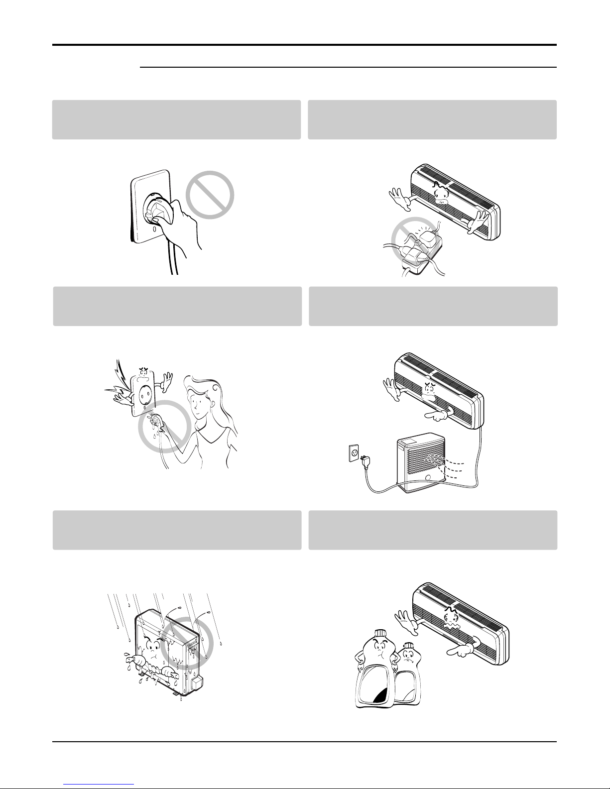
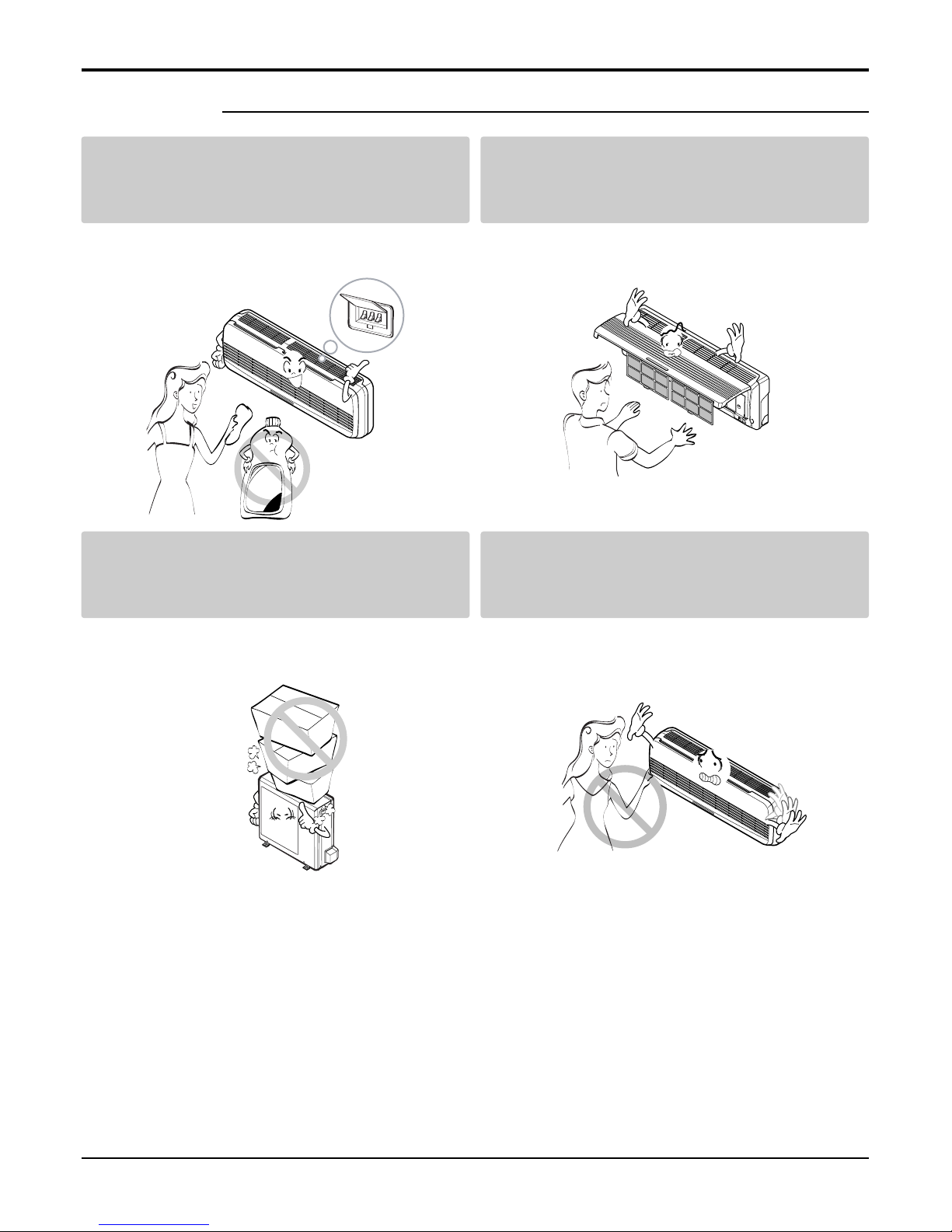
Safety Precautions..........................................................................................................................................5
Dimensions ...................................................................................................................................................10
Symbols Used in this Manual...................................................................................................................10
Indoor Unit................................................................................................................................................10
Outdoor Unit.............................................................................................................................................11
Product Specifications ................................................................................................................................13
Installation .....................................................................................................................................................14
Select the Best Location .........................................................................................................................14
Piping Length and Elevation.....................................................................................................................14
How to Fix Installation Plate.....................................................................................................................15
Drill a Hole in the Wall ..............................................................................................................................15
Installation Instructions of Telephone Control(Optional)...........................................................................15
Flaring Work.............................................................................................................................................16
Connection of Piping Indoor.....................................................................................................................17
Connection of the Pipes-Outdoor.............................................................................................................20
Connect the Cable to the Indoor Unit.......................................................................................................21
Connect the Cable to the Outdoor Unit ....................................................................................................22
Checking the Drainage.............................................................................................................................23
Form the Piping........................................................................................................................................23
Air Purging ...............................................................................................................................................24
Air Purging with Vacuum Pump................................................................................................................24
Test Running ............................................................................................................................................26
Operation ......................................................................................................................................................27
Function of Controls .................................................................................................................................27
Display Function.......................................................................................................................................34
Self-diagnosis Function............................................................................................................................35
Remote Control Operations......................................................................................................................36
Disassembly ..................................................................................................................................................37
Indoor Unit................................................................................................................................................37
Schematic Diagram.......................................................................................................................................41
Electric Control device..............................................................................................................................41
Wiring Diagram.........................................................................................................................................43
Components Location ..............................................................................................................................44
Troubleshooting Guide .................................................................................................................................46
Refrigeration Cycle Diagram ....................................................................................................................46
Pipe Length and the Elevation .................................................................................................................47
2-way, 3-way Valve ...................................................................................................................................48
Cycle Parts...............................................................................................................................................55
Electronic Parts ........................................................................................................................................56
Exploded View ..............................................................................................................................................63
Indoor Unit...............................................................................................................................................63
Outdoor Unit............................................................................................................................................64
Replacement Parts List ................................................................................................................................65
Indoor ......................................................................................................................................................65
Outdoor ....................................................................................................................................................66

Service Manual 3
LG Model Name
12 3456789
Code Type Code of Model Meaning
1,2 Type of Airconditioner A~Z LS: LG Split Type Airconditioner
3 Chassis A~Z Name of toll of Unit
Ex. LS-R ➔S R Chassis
4,5 Capacity(Btu/h) 1~9 Cooling/Heating Capacity
Ex. "09" ➔9,000Btu/h
6 Electric Range 1~9 Electric Standard
1 ➔115V/60Hz 6 ➔220~240V/50Hz
2 ➔ 220V/60Hz 7 ➔110V, 50/60Hz
3 ➔208~230V/60Hz 8 ➔380~415V/50Hz
5 ➔200~220V/50Hz 9 ➔380~415V/60Hz
7 Serial No. 0~9
A~Z
8 Cooling/Heating A~Z
9 LG/OEM Brand A~Z L: LG Brand M: 1st OEM Brand
G: 2nd LG Brand N: 2nd OEM Brand
-
Basic A 0
Plasma Filter B 1
Auto Swing
+ Plasma Filter C 2
Telephone + LED Display D 3
Telephone + LCD Display E 4
Auto Swing
+ Plasma Filter + Telephone + LCD
F5
Low Ambient + Ambient/change G 6
Plasma Filter + Low Ambient + Ambient/change
H7
Internet J 8
Auto Swing + Plasma Filter + Oxygen Generator
K9
Auto Swing + Soft Start ZL
Auto Swing + Star Rating M Y
Auto Swing + Star Rating + Plasma Filter N X
Auto Swing + Soft Start + Star Rating P W
Auto Swing + Soft Start + Star Rating 4 + Plasma
QV
Auto Swing + Telephone + LCD R U
Auto Swing + Telephone + LCD + Soft Start
ST
C/O
C
A
D
G
K
H/P
H
B
E
J
L
E/H+C/O
X
5
7
-
-
E/H+H/P
Y
6
8
-
-
C/O
F
M
Q
-
-
H/P
R
P
S
-
-
C/O
V
W
1
3
H/P
N
Y
2
4
H/P
T
H/P
U
INDOOR
BASIC
BASIC
PLASMA
PLASMA
GOLD FIN
OUTDOOR
BASIC
GOLD FIN
GOLD FIN
BASIC
GOLD FIN
UNIT
R22
HFC R22+AC INV.
HFC+AC
INV.
HFC+DC
INV.
2002

4Room Air Conditioner
12 - 345678910
Code Type Code of Model Meaning
1 Producing Center, A~Z L: Chang-won R22 N: India
Refrigerant A: Chang-won R410A Z: Brazil
C: Chang-won R407C D: Indonesia
T: China M: Mexico
K: Turkey R22 V: Vietnam
E: Turkey R410A S: Out Sourcing
H: Thailand
2 Product Type A~Z S: Split Type Air Conditioner
3 Cooling/Heating/Inverter A~Z C: Cooling only
H: Heat pump
X: C/O + E/Heater
Z: H/P + E/Heater
V: AC Inverter C/O
N: AC Inverter H/P
Q: DC Inverter C/O
W: DC Inverter H/P
4, 5 Capacity 0~9 Cooling/Heating Capacity
Ex. "09" →9,000 Btu/h
6 Electric Range 1~9 1: 115V/60Hz, A: 220V, 50Hz, 3Phase
A~Z 2: 220V/60Hz B: 208~230V, 60Hz, 3Phase
3: 208-230V/60Hz C: 575V, 50Hz, 3Phase
5: 200-220V/50Hz D: 440~460, 60Hz, 3Phase
6: 220-240V/50Hz E: 265V, 60Hz
7: 110V, 50/60Hz F: 200V, 50/60Hz
8: 380-415V/50Hz
9: 380-415V/60Hz
7 Chassis A~Z Name of Chassis of Unit
Ex. LSP →SP Chassis
8 Look A~Z Look,
Color (Artcool Model)
9 Function A~Z
10 Serial No. 1~9 LG Model De
* ARTCOOL COLOR
velopment Serial No.
Basic A
Basic+4Way B
Plasma Filter C
Plasma Filter+4 Way D
Tele+LCD E
Tele+LCD+Nano plasma+4Way F
Nano Plasma F+(A/changeove)+A/clean+Low A G
Nano Plasma F+(A/changeove)+A/clean+4way+Low A H
Tele+LED+4way I
Internet J
Plasma F+4Way+Oxy generator K
Nano Plasma F+(A/changeove)+A/clean L
Nano Plasma F+(A/changeove)+A/clean+4way M
Nano Plasma F+(A/changeove)+A/clean+PTC N
Nano Plasma F+(A/changeove)+Autoclean+4way+PTC P
Nano Plasma F+(A/changeove)+A/clean+4way+Low A+PTC Q
Negative ION+A/Clean R
(Nano)Plasma+Negative ION+A/Clean S
4way+(Nano)Plasma F+Negative ION+Healthy dehumidification+A/Clean
T
Nano Plasma F+4Way+(A/changeove)+A/clean+ U
R Mirror
W White
B Blue
D Wood
M Metal
C Cherry
2003

Service Manual 5
Safety Precautions
Safety Precautions
To prevent injury to the user or other people and property damage, the following instructions must
be followed.
■Incorrect operation due to ignoring instruction will cause harm or damage. The seriousness is
classified by the following indications.
■Meanings of symbols used in this manual are as shown below.
This symbol indicates the possibility of death or serious injury.
This symbol indicates the possibility of injury or damage to properties only.
Be sure not to do.
Be sure to follow the instruction.
Do not use damaged power cords, plugs, or a
loose socket.
Always use the power plug and socket with the
ground terminal.
• There is risk of fire of electric shock. • There is risk of electric shock.
Install the panel and the cover of control box
securely.
.Do not modify or extend the power cord.
• There is risk of fire of electric shock. • No grounding may cause electric shock.
■Installation

6Room Air Conditioner
Safety Precautions
Do not install the product on a defective instal-
lation stand.
Be sure the installation area does not
deteriorate with age.
• It may cause injury, accident, or damage to the
product.
• If the base collapses, the air conditioner could fall
with it, causing property damage, product failure,
and personal injury.
• Sharp edges could cause injury. Be especially care-
ful of the case edges and the fins on the condenser
and evaporator.
•
There is risk of fire, electric shock, explosion, or injury.
Be cautious when unpacking and installing the
product.
For installation, always contact the dealer or
an Authorized service center
For re-installation of the installed product,
always contact a dealer or an authorized ser-
vice center.
Do not install, remove, or re-install the unit by
yourself.
• There is risk of fire, electric shock, explosion, or
injury.
• There is risk of fire, electric shock, explosion, or
injury.

Service Manual 7
Safety Precautions
■Operation
Do not turn the air-conditioner ON or OFF by
plugging or unplugging the power plug.
Use a dedicated outlet for this appliance.
• There is risk of fire or electrical shock. • There is risk of fire or electrical shock.
Grasp the plug to remove the cord from the
outlet. Do not touch it with wet hands.
Do not place a heater or other appliances near
the power cable.
• There is risk of fire or electrical shock. • There is risk of fire and electric shock.
Do not allow water to run into electrical parts. Do not store or use flammable gas or com-
bustibles near the air conditioner.
• There is risk of fire, failure of the product, or electric
shock.
• There is risk of fire or failure of product.
Wax
Thinner

8Room Air Conditioner
Always check for gas (refrigerant) leakage after
installation or repair of product.
Install the drain hose to ensure that water is
drained away properly.
• Low refrigerant levels may cause failure of product. • A bad connection may cause water leakage.
Keep level even when installing the product. Use two or more people to lift and transport
the air conditioner.
• To avoid vibration or water leakage. • Avoid personal injury.
■Installation
90˚
Unplug the unit if strange sounds, odors, or
smoke comes from it.
Be cautious that water could not enter the
product.
• There is risk of electric shock or fire. • There is risk of fire, electric shock, or product dam-
age.

Service Manual 9
Use a soft cloth to clean. Do not use harsh
detergents, solvents, etc.
Do not touch the metal parts of the product
when removing the air filter. They are very
sharp!
• There is risk of fire, electric shock, or damage to the
plastic parts of the product.
• There is risk of personal injury.
Do not step on or put anyting on the product.
(outdoor units)
Do not insert hands or other objects through
the air inlet or outlet while the air conditioner
is plugged in.
• There is risk of personal injury and failure of product. • There are sharp and moving parts that could cause
personal injury.
■Operation
Wax

10 Room Air Conditioner
Dimensions
Dimensions
Installation plate
D
H
W
W mm 824 900
H mm 260 285
D mm 155 156
Model
Dimension 7, 9k Btu Series 12k Btu Series
Indoor Unit
This symbol alerts you to the risk of electric shock.
This symbol alerts you to hazards that could cause harm to the
air conditioner.
This symbol indicates special notes.
NOTICE
Symbols Used in this Manual

Service Manual 11
Outdoor Unit
Dimensions
WL2
L3
L1
D
H
L4
L5
Gas side
(3-way valve)
Liquid side
(2-way valve)
MODEL 7k Btu Series
DIM unit
W mm 564
H mm 525
D mm 265
L1 mm 294
L2 mm 66
L3 mm 374
L4 mm 17
L5 mm 270

12 Room Air Conditioner
WL2
L3
L1
D
H
L4
L5
Gas side
(3-way valve)
Liquid side
(2-way valve)
MODEL 9k, 12k Btu Series
DIM unit
W mm 770
H mm 540
D mm 245
L1 mm 285
L2 mm 65
L3 mm 518
L4 mm 10
L5 mm 100
Dimensions

Service Manual 13
Product Specifications
Table-1
Model Name
Item Unit
Cooling Capacity Btu/h
Heating Capacity
Moisture Removal l/h
Power Source Ø, V, Hz
Cooling W
Heating
Running Cooling A
Current Heating
E.E.R. Cooling Btu/hW
C.O.P Heating
Refrigerant g
Airflow Direction Control (Up & Down)
Remocon Type
inch(mm)
Sleeping Operation
Drain Hose
Connecting Cable(p*mm2)
Power Cord(p*mm2)
Air Circulation
Noise Level
Input
m3/min
dB (A)±3
Indoor
Outdoor
Indoor
Outdoor
Indoor
Outdoor
Indoor
Outdoor
Indoor
Outdoor
Liquid
Gas
Service Valve
Motor Output
Dimensions
(W x H x D)
Net. Weight
W
mm
kg
LS-H076QLN0 LS-H096QLN0 LS-H126RLN1
7,000 9,000 12,000
7,300 9,300 13,000
1 1 1.5
1Ø, 220-240V, 50Hz 1Ø, 220-240V, 50Hz 1Ø, 220-240V, 50Hz
5.9 6 9.5
20 25 26
34 36 40
48 48 49
660 950 1,270
640 860 1,230
3 4.2 5.8
2.9 3.8 5.6
10.6 9.5 9.45
3.3 2.8 3.1
5 8.4 9.5
14 13.6 25
824 x 260 x 155 824 x 260 x 155 900 x 285 x 156
525 x 564 x 265 770 x 540 x 245 770 x 540 x 245
778
23 23 35
610(R22) 680(R22) 850(R22)
OOO
L.C.D Wireless L.C.D Wireless L.C.D Wireless
1/4 (6.35) 1/4 (6.35) 1/4 (6.35)
3/8 (9.52) 3/8 (9.52) 12(12.7)
OOO
OOO
3 * 1.0mm2+ 2 * 0.75mm23 * 1.0mm2+ 2 * 0.75mm23 * 1.0mm2+ 2 * 0.75mm2
3 * 1.0mm23 * 1.0mm23 * 1.5mm2

14 Room Air Conditioner
Installation
Installation
Indoor unit
•Do not have any heat or steam near the unit.
•Select a place where there are no obstacles in
front of the unit.
•Make sure that condensation drainage can be con-
veniently routed away.
Do not install near a doorway.
•Ensure that the space around the left and right of
the unit is more than "A". The unit should be
installed as high on the wall as possible, allowing a
minimum of "B" from ceiling.
•Use a stud finder to locate studs to prevent unnec-
essary damage to the wall.
Outdoor unit
•If an awning is built over the unit to prevent direct
sunlight or rain exposure, make sure that heat
radiation from the condenser is not restricted.
•Ensure that the space around the back and sides
is more than 10cm. The front of the unit should
have more than 70cm of space.
•Do not place animals and plants in the path of the
warm air.
•Take the air conditioner weight into account and
select a place where noise and vibration are mini-
mum.
•Select a place so that the warm air and noise from
the air conditioner do not disturb neighbors.
More than "A"
More than "B"
More than 2.3m More than "B"
More than 10cm More than 10cm
More
than 60cm
More than 60cm
More than 70cm
CAUTION: Install the indoor unit on the wall
where the height from the floors more than 2.3
meters.
CAUTION:
• Capacity is based on standard length and maximum
allowance length is on the basis of reliability.
• Oil trap should be installed every 5~7 meters.
Grade Clearance(cm)
AB
7K~28K 10 5
30K~38K 30 12
Pipe Size
Capacit
y
(Btu/h) GAS LIQUID
Max.
Length
A (m)
Additional
Refrigerant
(g/m)
Max.
Elevation
B(m)
Standard
Length
(m)
7k~14k 3/8"(Ø9.52) 1/4"(Ø6.35) 4 or 7.5 7 15 20
1/2"(Ø12.7) 1/4"(Ø6.35) 4 or 7.5 7 15 20
1/2"(Ø12.7) 1/4"(Ø6.35) 4 or 7.5 15 30 20
18k~28k 5/8"(Ø15.88) 1/4"(Ø6.35) 4 or 7.5 15 30 20
5/8"(Ø15.88) 3/8"(Ø9.52) 4 or 7.5 15 30 30
30k~38k 5/8"(Ø15.88) 3/8"(Ø9.52) 7.5 15 30 30
3/4"(Ø19.05) 3/8"(Ø9.52) 7.5 15 30 50
If case more than 5m
Outdoor unit
Indoor unit
A
B
Outdoor unit
Indoor unit
A
B
A
Oil trap
Outdoor unit
Indoor unit
B
I
Selection of the Best Location
Piping Length and Elevation

Service Manual 15
Installation
The wall you select should be strong and solid
enough to prevent vibration
1. Mount the installation plate on the wall with four
type A screws. If mounting the unit on a concrete
wall, use anchor bolts.
•Mount the installation plate horizontally by aligning
the centerline using a level.
2. Measure the wall and mark the centerline. It is
also important to use caution concerning the
location of the installation plate-routing of the
wiring to power outlets is through the walls typi-
cally. Drilling the hole through the wall for pip-
ing connections must be done safely.
•Drill the piping hole with a ø70mm hole core drill.
Drill the piping hole at either the right or the left
with the hole slightly slanted to the outdoor side.
•Open the Front Grille.
•Pass Telephone Control Cord Wire through the
hole which the power cord goes through.
•Connect Telephone Control Cord Wire to the
phone jack of telephone PCB of Control Box.
•Fix Telephone Control Cord Wire inside Control
box so as not to disconnect.
•Close the Front Grille.
Installation Plate
Type "A" screw
5-7mm
(3/16"~5/16")
Indoor
WALL
Outdoor
Answering telephone / Normal telephone
(Not packed in the box)
Adaptor
(Not packed in
the box)
Telephone Control
Cord Wire
(Packed in the box)
Phone
Conductor
Installation plate
Ø70mm
Left rear piping Right rear piping
C
D
B
AØ70mm
Ø70mm
Left rear piping Right rear piping
CE A
B
D
Installation plateInstallation plate
ABCD
SJ 90 20 80 20
SL, SK 45 40 80 20
SQ 75 12 80 12
SR 0 40 20 40
ST 105 0 210 0
CHASSIS
(Grade)
Distance (mm)
How to Fix Installation Plate Drill a Hole in the Wall
Installation Instructions of Telephone Control(Optional)
ABC DE
SM 180 115 - 115 50
SN 180 115 195 115 -
CHASSIS
(Grade)
Distance (mm)

16 Room Air Conditioner
Installation
Flaring Work
Main cause for refrigerant leakage is due to defect in
the flaring work. Carry out correct flaring work using the
following procedure.
Cut the pipes and the cable.
•Use the piping kit accessory or pipes purchased
locally.
•Measure the distance between the indoor and the
outdoor unit.
•Cut the pipes a little longer than the measured
distance.
•Cut the cable 1.5m longer than the pipe length.
Burr removal
•Completely remove all burrs from the cut cross
section of pipe/tube.
•Put the end of the copper tube/pipe in a downward
direction as you remove burrs in order to avoid
dropping burrs into the tubing.
Putting nut on
•Remove flare nuts attached to indoor and outdoor
unit, then put them on pipe/tube having completed
burr removal.
(not possible to put them on after flaring work)
Flaring work
•Firmly hold copper pipe in a die in the dimension
shown in the table above.
•Carry out flaring work using flaring tool as shown
below.
Check
•Compare the flared work with figure below.
•If flare is noted to be defective, cut off the flared
section and re-flare it.
Copper
pipe
90°Slanted Uneven Rough
Bar
Copper pipe
Clamp handle Red arrow mark
Cone
Yoke
Handle
Bar
"A"
Inclined
Inside is shiny without scratches
Smooth all round
Even length
all round
Surface
damaged
Cracked Uneven
thickness
= Improper flaring =
Pipe
Reamer
Point down
Flare nut
Copper tube
mm inch mm
Ø6.35 1/4 0~0.5
Ø9.52 3.8 0~0.5
Ø12.7 1/2 0~0.5
Ø15.88 5/8 0~1.0
Ø19.05 3/4 1.0~1.3
Outside diameter A

Service Manual 17
Installation
Connection of Piping Indoor
•Preparing the indoor unit's piping and drain hose
for installation through the wall.
•Remove the plastic tubing retainer(see illustration
below) and pull the tubing and drain hose away
from chassis.
•Replace the plastic tubing holder in the original
position.
For right rear piping
1. Route the indoor tubing and the drain hose in
the direction of rear right.
2. Insert the connecting cable into the indoor unit
from the outdoor unit through the piping hole.
•Do not connect the cable to the indoor unit.
•Make a small loop with the cable for easy
connection later.
3. Tape the tubing, drain hose, and the connecting
cable. Be sure that the drain hose is located at
the lowest side of the bundle. Locating at the
upper side can cause drain pan to overflow
inside the unit.
If the drain hose is routed inside the
room, insulate the hose with an insula-
tion material* so that dripping from
"sweating"(condensation) will not dam-
age furniture or floors.
*Foamed polyethylene or equivalent is recom-
mended.
4. Indoor unit installation
•Hook the indoor unit onto the upper portion of the
installation plate.(Engage the two hooks of the rear
top of the indoor unit with the upper edge of the
installation plate.) Ensure that the hooks are prop-
erly seated on the installation plate by moving it
left and right.
Press the lower left and right sides of the unit against the
installation plate until the hooks engage into their
slots(clicking sound).
4. Connecting the pipings to the indoor unit and
drain hose to drain pipe.
•Align the center of the pipes and sufficiently tight-
en the flare nut by hand.
NOTICE
CAUTION:
When
install, make sure
that the remaining
parts must be removed
clearly so as not to dam-
age the piping and drain
hose, especially power
cord and connecting cable.
Tubing holder
Connecting
cable
Loop
Gas side
piping
Liquid side
piping
Drain hose
Drain hose
Connecting
cable
Indoor unit tubing Flare nut Pipes
Drain hose

18 Room Air Conditioner
Installation
•Tighten the flare nut with a wrench.
•When extending the drain hose at the indoor unit,
install the drain pipe.
5. Wrap the insulation material around the con-
necting portion.
•Overlap the connection pipe insulation material
and the indoor unit pipe insulation material. Bind
them together with vinyl tape so that there is no
gap.
•Wrap the area which accommodates the rear pip-
ing housing section with vinyl tape.
•Bundle the piping and drain hose together by
wrapping them with vinyl tape for enough to cover
where they fit into the rear piping housing section.
For left rear piping
1. Route the indoor tubing and the drain hose to
the required piping hole position.
2. Insert the piping, drain hose, and the connecting
cable into the piping hole.
mm inch kg.m
Ø6.35 1/4 1.8
Ø9.52 3.8 4.2
Ø12.7 1/2 5.5
Ø15.88 5/8 6.6
Ø19.05 3/4 6.6
Outside diameter Torque
Wrench
Indoor unit tubing
Open-end wrench (fixed)
Connection pipe
Flare nut
Vinyl tape(narrow)
Adhesive
Drain pipe
Indoor unit drain hose
Plastic bands Insulation material
Vinyl tape(narrow)
Connection
pipe
Connecting cable
Vinyl tape
(wide) Wrap with vinyl tape
Indoor
unit pipe
Pipe
Drain hose
Connecting
cable
Drain pipe
Connecting cable

Service Manual 19
Installation
3. Insert the connecting cable into the indoor unit.
•Don't connect the cable to the indoor unit.
•Make a small loop with the cable for easy connec-
tion later.
4. Tape the drain hose and the connecting cable.
•Connecting cable
5. Indoor unit installation
•Hang the indoor unit from the hooks at the top of
the installation plate.
•Insert the spacer etc. between the indoor unit and
the installation plate and separate the bottom of
the indoor unit from the wall.
6. Connecting the pipings to the indoor unit and
the drain hose to drain pipe.
•Align the center of the pipes and sufficiently tight-
en the flare nut by hand.
•Tighten the flare nut with a wrench.
•When extending the drain hose at the indoor unit,
install the drain pipe.
7. Wrap the insulation material around the con-
necting portion.
•Overlap the connection pipe heat insulation and
the indoor unit pipe heat insulation material. Bind
them together with vinyl tape so that there is no
gap.
•Wrap the area which accommodates the rear pip-
ing housing section with vinyl tape.
mm inch kg.m
Ø6.35 1/4 1.8
Ø9.52 3.8 4.2
Ø12.7 1/2 5.5
Ø15.88 5/8 6.6
Ø19.05 3/4 6.6
Outside diameter Torque
Vinyl tape
Adhesive
Drain hose
Indoor unit drain hose
(narrow)
Plastic bands Insulation material
Vinyl tape(narrow)
Connection
pipe
Connecting cable
Indoor
unit piping
Pipe
Vinyl tape
(wide) Wrap with vinyl tape
Installation plate
Spacer
Indoor unit
8cm
Indoor unit tubing Flare nut Pipes
Wrench
Indoor unit tubing
Connection pipe
Flare nut
Open-end wrench (fixed)

20 Room Air Conditioner
Installation
•Bundle the piping and drain hose together by
wrapping them with cloth tape over the range with-
in which they fit into the rear piping housing sec-
tion.
8. Reroute the pipings and the drain hose across
the back of the chassis.
9. Set the pipings and the drain hose to the back of
the chassis with the tubing holder.
•Hook the edge of tubing holder to tap on chassis
and push the bottom of tubing holder to be
engaged at the bottom of chassis.
10. Indoor unit installation
•Remove the spacer.
•Ensure that the hooks are properly seated on the
installation plate by moving it left and right.
Press the lower left and right sides of the unit against the
installation plate until the hooks engage into their
slots(clicking sound).
1. Align the center of the pipings and sufficiently
tighten the flare nut by hand.
2. Finally, tighten the flare nut with torque wrench
until the wrench clicks.
•When tightening the flare nut with torque wrench,
ensure the direction for tightening follows the
arrow on the wrench.
mm inch kg.m
Ø6.35 1/4 1.8
Ø9.52 3/8 4.2
Ø12.7 1/2 5.5
Ø15.88 5/8 6.6
Ø19.05 3/4 6.6
Outside diameter Torque
Drain hose
Vinyl tape(narrow)
Pipe
Wrap with
vinyl tape(wide)
Piping for
passage through
piping hole
Outdoor unit
Gas side piping
(Bigger diameter)
Liquid side
piping
(Smaller
diameter)
Torque wrench
Tubing holder
Drain hose
Connecting
cable
Connection of the Pipes-Outdoor
This manual suits for next models
2
Table of contents
Other LG Air Conditioner manuals
Popular Air Conditioner manuals by other brands

Whirlpool
Whirlpool R1011 Installation Instructions and Use & Care Guide

Goodman
Goodman GSH Series Service instructions

Copa
Copa COPA 43 user manual

Woods
Woods HT Installation Guide & Technical Specifications

Lennox
Lennox LI012HI-210P432 Service manual

Inventor Air Conditioners
Inventor Air Conditioners WGN18D/GN18D Service manual