LG LG-600 Series Operating instructions

GSM Handsets Lab.
GSM Phone
REPAIR MANUAL
MODEL : LG-600 Series

GSM Handsets Lab. 2
1. INTRODUCTION .…………………………………
1.1 Purpose .…………………………………..…...
1.2 Abbreviations ………………………………...
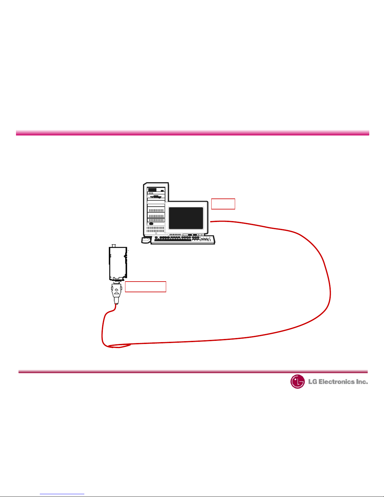
2. TEST SETUP ………………………………..…....
2.1 Normal Setup …..……………………..…....
2.2 Standard Setup .………..……………..…....
3. ASSEMBLY INSTRUCTION ……………………
3.1 Assembly / Diassembly ……………………
3.2 Assembly / Diassembly of Front Cover
Componet …………………………………..
4. DOWNLOAD .……………………………………
.1 Download Setup ……..…………………………
.2 Download ……………………….………………
5. ENGINEERING MODE ………………
5.1 BB Test ………………………………
5.2 Trace Test …………………………
5.3 S/W Version …………………………
5. SIM Lock ……………………………
5.5 Call Timer ……………………………
5.6 Fact. Reset …………………………
6. TROUBLE SHOOTING ………………
6.1 Power Supply…………………………
6.2 Voice ………………………………...
6.3 Display ………………………………
6. Rx and Tx .……………………………
6.5 The Other Function …………………
A endix
A.1 RF Component …………………….
A.2 Receiver RF Block Diagram .…….
A.3 Transmitter RF Block Diagram ….
A. Rx Flow Chart & Solution ………….
A.5 Tx Flow Chart & Solution ………….
A.6 MIC Flow Chart & Solution ……….
A.7 Receive Flow Chart & Solution ….
A.8 LCD Flow Chart & Solution ……….
Table of Contents
3
3
6
6
7
11
11
12
1
1
15
16
17
19
19
19
19
19
20
20
28
3
1
6
48
8
50
51
52
67
78
83
86

GSM Handsets Lab. 3
1. INTRODUCTION
•1.1 Purpose
This manual provides the information necessary to repair, description
and download the features of the LG-600 series, specially this book has
the chip aim of our repair men to improve their ability.
• Applicability
This trouble shooting is only applicable to professional engineer for
repairing mobile phone.
• Maintenance Limitations
Maintenance limitations on the LG-600 series must be
performed only by the LGE or its authorized agent. The user
may not make any changes and or repairs expect as speci"cally
noted in this manual. Therefore, note that unauthorized
alternations or repair may a$ect the regulatory status of the
system and may void any remaining warranty.

GSM Handsets Lab. 4
1. INTRODUCTION
aseband
LDO Low Drop Output
LED Light Emitting Diode
CC-CV Constant Current – Constant Voltage
CLA Cigar Lighter Adapter
DAC Digital to Analog Converter
DCS Digital Communication System
DSP Digital Signal Processing
EL Electroluminescence
ESD Electrostatic Discharge
FPC Flexible Printed Circuit oard
GMSK Gaussian Minimum Shift Keying
GPI General Purpose Interface us
GPRS General Packet Radio Service
GSM Global System for Mobile Communications
UART Universal Asynchronous Receiver/Transmitter
IF Intermediate Frequency
LCD Liquid Crystal Display
PC Printed Circuit oard
PSTN Public Switched Telephone Network
RF Radio Frequency
RTC Real Time Clock
SIM Subscriber Identity Module
SRAM Static Random Access Memory
TA Travel Adapter
TDD Time Division Duplex
TDMA Time Division Multiple Access
WAP Wireless Application Protocol
IPUI International Portable User Identity
•1.2 Abbreviations

GSM Handsets Lab.
1. INTRODUCTION
ATTENTION
oards, which contain Electrostatic Sensitive Device (ESD), are indicated by the
sign. Following information is ESD handling:
Service personnel should ground themselves by using a wrist strap when
exchange system boards.
When repairs are made to a system board, they should spread the floor with
anti-static mat which is also grounded.
Use a suitable, grounded soldering iron.
Keep sensitive parts in these protective packages until these are used.

GSM Handsets Lab. 6
2. TEST SETUP
•2.1 Normal Setup
COMPUTER
LG-600
RS-232CABLE
COM1
I/OConnector

GSM Handsets Lab. 7
2. TEST SETUP
•2.2 Standard Setup
COMPUTER
MON
UART
PHONE
POWER
DIPS/W
PIF(LG-600JIG)
POWERSUPPLY
GSMTESTSET(8 60)
LG-600
MOBILERFCABLE
POWERCABLE
RS-232CABLE
I/OCON.CABLE
SPECTRUMANALYZER
HIGHFREQUENCYPROBE
OSCILLOSCOPE
PROBE
GPIBCABLE
+-
-S-++S
GPIB
GPIB GPIB COM1
GPIB
GPIBCABLE
RFIN/OUT
I/OConnector

GSM Handsets Lab. 8
2. TEST SETUP
A. Com uter
1. Put GPIB card to the extended slot of personal computer.
If you have a notebook PC, you need PCMCIA card for GPIB.
2. Connect the RS-232 cable between COM port of your PC and MON port or
UART port of PIF.
MON Port : Download, CAL Test (????)
UART : Auto Test or Handsfree_Set (????)
B. GSM TEST_SET(8960)
1. Connect GPIB cables (from Computer and Power Supply) to the rear panel
of 8960.
2. Connect mobile RF cable to RF In/Out port at the front panel of 8960.
C. Power Su ly
1. Setup : Voltage .0V, max Current 3A.
2. Connect GPIB cable at the rear panel.
3. Connect power cable

GSM Handsets Lab. 9
2. TEST SETUP
PIF DIP Switch
D. PIF(JIG for LG 600)
1. Connect I/O connector cable for 600 to PIF phone port.
2. Connect the power cable ro PS port of PIF.
3. Connect the RS-232 cable ro PIF MON or UART.
ON
ON
OFF
DC
PS
REMOTE
H/F
DIP Switch
*H/F=Hands Free
*PS=Power Su ly

GSM Handsets Lab. 10
2. TEST SETUP
D. PIF(JIG for LG 600)
JTAG1 AUDIOJTAG2
MON
UART
PHONE
TA MON
Status
UART
Status
Power
+ PS -
DC IN
12V
TA

GSM Handsets Lab. 11
3. ASSEMBLY INSTRUCTION
•3.1 Assembly / Disassembly

GSM Handsets Lab. 12
3. ASSEMBLY INSTRUCTION
•3.2 Assembly / Disassembly of Front Cover Components

GSM Handsets Lab. 13
3. ASSEMBLY INSTRUCTION
•3.3 Assembly / Disassembly of Folder

GSM Handsets Lab. 14
4. DOWNLOAD
COMPUTER
LG-600
RS-232CABLE
COM1
I/OConnector
.1 Download Setup

GSM Handsets Lab. 1
4. DOWNLOAD
•.2 Download
Choose
“Target/Connect
”
Choose Correct
Serial Port
Press
“PWRON”
of LG-600
Erase all
Erase and Program Appli+Boot Downloading
Software
Download Completed
Caution !!!
Remove Battery

GSM Handsets Lab. 16
5. ENGINEERING MODE
Enter : 294 #*
•About Engineering Mode
Engineering mode is designed to allow a service man/engineer to view
and test the basic funtions provided by a hanset.
• Access Codes
The key sequence for switching the engineering mode on is 2945#*
Pressing END will switch back to non-engineering mode operation.
• Key O eration
Use Up and Down key to select a menu and press ‘select’ key
to progress the test. Press ‘back’ key will switch back to the
original test menu.
This mode is used to certify that which art is needed to re air so sim ly.
This art is consist of BB test, RF test, MF test, SW version and so on.

GSM Handsets Lab. 17
5. ENGINEERING MODE
5.1 Baseband Test [MENU 1]
A. LED Test [1-2]
This menu is to test the indicator LED on top left hand corner of a handset and backlight
LED in the LCD module.
• Auto Test [1-2-1]
• Indicator On [1-2-2] : Green light turns on and menu is changed to “Indicator Off”.
• Back Light On [1-2-3] : Back Light turns on and menu is changed to “Indicator Off”.
• Back Light Degree [1-2-4] : This controls brightness of Backlight. When entering into
the menu, the present backlight-value in the phone is displayed. Use Left/Right key to
adjust the level of brightness. The value of the brightness set at last will be saved.
B. LCD Test [1-3]
This menu is to test the LCD module.
• Auto Test [1-3-1] • Font [1-3-2]
• Icons [1-3-3] • Animation [1-3-4]
• LCD Parameters [1-3-5] • Reset Period [1-3-6]

GSM Handsets Lab. 18
5. ENGINEERING MODE
C. Key ad Test [1-4]
D. Melody Test [1-5]
• Auto Test [1-5-1]
• Melody Pattern [1-5-2]
• Melody Volume [1-5-3]
E. Vibrator [1-6]
F. Battery Test [1-7]
G. Serial Port Test [1-8]
H. Audio Gain Test [1-9]
• Receiver [1-9-1] : Voice[1-9-1-1], Keytone[1-9-1-2], Echo Control[1-9-1-3]
• Earmic [1-9-2] : Voice[1-9-2-1], Keytone[1-9-2-2], Echo Control[1-9-2-3]
• Louds eaker [1-9-3] : Voice[1-9-3-1], Keytone[1-9-3-2], Echo Control[1-9-3-3]
• Handsfree [1-9-4] : Voice[1-9- -1], Keytone[1-9- -2], Echo Control[1-9- -3]
• Default value [1-9-5]
I. Dee Slee Test [1-10]

GSM Handsets Lab. 19
5. ENGINEERING MODE
5.2 Trace Test [MENU 2]
S/W Version [MENU 3] : This displays software version stored in the phone.
5.3 Eng Mode [MENU 4]
5.4 SIM Lock [MENU 5]
5.5 Call Timer [MENU 6]
A. All Calls [6-1] : This displays total conversation time. User cannot reset this value.
B. Reset settings [6-2] : This resets total conversation time to this, [00:00:00].
5.6 Fact. Reset [MENU 7]
This Factory Reset menu is to format data block in the flash memory and this procedure
set up the default value in data block.
Attention
Fact. Reset (i.e.Factory Reset) should be only used during the Manufacturing process.
Servicemen should NOT rogress this menu, otherwise some of valuable data such
as Setting value, RF Calibration data, etc. cannot be restored again.

GSM Handsets Lab. 20
6. TROUBLE SHOOTING
6.1 Power On Trouble
Failure : Power-ON button is not working.
Solution :
- Check the voltage level
of battery.
- If voltage level < 3.32 v,
Charge the battery.
- If voltage level > 3.32 v,
Go on to the next age.
TOP
Battery
Other manuals for LG-600 Series
1
Table of contents
Other LG Cell Phone manuals