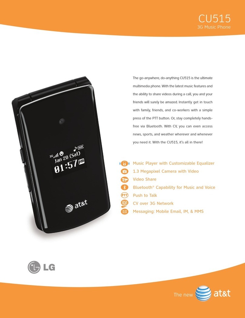
LG LG-S310 User manual

Service Manual Model : LG-S310
Internal Use Only
Service Manual
LG-S310
Date: December, 2010 / Issue 1.1

- 3 -
Copyright © 2010 LG Electronics. Inc. All right reserved.
Only for training and service purposes
LGE Internal Use Only
Table Of Contents
1. INTRODUCTION..................................................................5
1.1 Purpose............................................................................................... 5
1.2 Regulatory Information ............................................................... 5
1.3 Abbreviations................................................................................... 7
2. PERFORMANCE...................................................................9
2.1 HW Feature........................................................................................ 9
2.2 RF Spec..............................................................................................10
3. TECHNICAL BRIEF.............................................................11
3.1 General Description.....................................................................11
3.2 GSM Part...........................................................................................12
3.3 Functional Block Diagram.........................................................19
3.4 Baseband Processor Introductions .......................................20
3.5 Charging Control ..........................................................................31
3.6 Power ON/OFF...............................................................................33
3.7 SIM Interface...................................................................................34
3.8 MICRO SD Card Socket (ENSY0018601) ..............................35
3.9 Memory............................................................................................37
3.10 LCD Display...................................................................................40
3.11 LCD Backlight Illumination ....................................................42
3.12 Keypad Switching & Scanning..............................................45
3.13 Keypad Backlight Illumination .............................................46
3.14 u USB Multimedia interface connector.............................47
3.15 Camera...........................................................................................48
3.16 Audio...............................................................................................49
3.17 Bluetooth/FM (WYSBNBGX6)................................................55
4. TROUBLE SHOOTING .......................................................59
4.1 Trouble shooting test setup.....................................................59
4.2 Power on trouble..........................................................................60
4.3 Charging Trouble..........................................................................63
4.4 USB Trouble.....................................................................................65
4.5 SIM Detect Trouble.......................................................................68
4.6 Key Sense Trouble ........................................................................70
4.7 Keypad Backlight Trouble .........................................................73
4.8 Micro SD Trouble ..........................................................................75
4.9 Audio Trouble.................................................................................78
4.10 Camera Trouble...........................................................................93
4.11 Main LCD Trouble.......................................................................96
4.12 Vibrator Trouble..........................................................................99
4.13 BT Trouble .................................................................................. 101
4.14 FM Trouble................................................................................. 109
4.15 RF Trouble Shooting .............................................................. 121
5. DOWNLOAD................................................................... 139
6. BLOCK DIAGRAM........................................................... 155
7. CIRCUIT DIAGRAM ........................................................ 161
8. BGA Pin Map.................................................................. 171
9. PCB LAYOUT................................................................... 176
10. CALIBRATION............................................................... 183
10.2 Usage of Tachyon for RF Calibration and Test ............. 183
11. TEST MODE .................................................................. 186
12. EXPLODED VIEW & REPLACEMENT PART LIST ......... 191
12.1 EXPLODED VIEW...................................................................... 191
12.2 Replacement Parts.................................................................. 193
12.3 Accessory ................................................................................... 207

- 4 -
LGE Internal Use Only Copyright © 2010 LG Electronics. Inc. All right reserved.
Only for training and service purposes

- 5 -
Copyright © 2010 LG Electronics. Inc. All right reserved.
Only for training and service purposes
LGE Internal Use Only
1. INTRODUCTION
1. INTRODUCTION
XUGpu{yvk|j{pvuG
1. INTRODUCTION
1.1 Purpose
This manual provides the information necessary to repair, calibration, description and download the features
of the LG-S310.
1.2 Regulatory Information
A. Security
Toll fraud, the unauthorized use of telecommunications system by an unauthorized part (for example,
persons other than your company’s employees, agents, subcontractors, or person working on your
company’s behalf) can result in substantial additional charges for your telecommunications services. System
users are responsible for the security of own system.
There might be risks of toll fraud associated with your telecommunications system. System users are
responsible for programming and configuring the equipment to prevent unauthorized use. LGE does not
warrant that this product is immune from the above case but will prevent unauthorized use of common
carrier telecommunication service of facilities accessed through or connected to it. LGE will not be
responsible for any charges that result from such unauthorized use.
B. Incidence of Harm
If a telephone company determines that the equipment provided to customer is faulty and possibly causing
harm or interruption in service to the telephone network, it should disconnect telephone service until repair
can be done. A telephone company may temporarily disconnect service as long as repair is not done.
C. Changes in Service
A local telephone company may make changes in its communications facilities or procedure. If these
changes could reasonably be expected to affect the use of the LG-S310 or compatibility with the net work,
the telephone company is required to give advanced written notice to the user, allowing the user to take
appropriate steps to maintain telephone service.
D. Maintenance Limitations
Maintenance limitations on the LG-S310 must be performed only by the LGE or its authorized agent. The user
may not make any changes and/or repairs expect as specifically noted in this manual. Therefore, note that
unauthorized alternations or repair may affect the regulatory status of the system and may void any
remaining warranty.

- 6 -
LGE Internal Use Only Copyright © 2010 LG Electronics. Inc. All right reserved.
Only for training and service purposes
1. INTRODUCTION
snTzZXWGGG
Z
Copyright ཱྀ2010 LG Electronics. Inc. All right reserved.
Only for training and service purposes LGE Internal Use Onl
y
E. Notice of Radiated Emissions
This model complies with rules regarding radiation and radio frequency emission as defined by local
regulatory agencies. In accordance with these agencies, you may be required to provide information such as
the following to the end user.
F. Pictures
The pictures in this manual are for illustrative purposes only; your actual hardware may look slightly different.
G. Interference and Attenuation
LG-S310 may interfere with sensitive laboratory equipment, medical equipment, etc. Interference from
unsuppressed engines or electric motors may cause problems.
H. Electrostatic Sensitive Devices
ATTENTION
Boards, which contain Electrostatic Sensitive Device (ESD), are indicated by the sign. Following
information is ESD handling:
• Service personnel should ground themselves by using a wrist strap when exchange system boards.
• When repairs are made to a system board, they should spread the floor with anti-static mat which is also
grounded.
• Use a suitable, grounded soldering iron.
• Keep sensitive parts in these protective packages until these are used.
• When returning system boards or parts like EEPROM to the factory, use the protective package as described.

- 7 -
Copyright © 2010 LG Electronics. Inc. All right reserved.
Only for training and service purposes
LGE Internal Use Only
1. INTRODUCTION
snTzZXWGGG
[
Copyright ཱྀ2010 LG Electronics. Inc. All right reserved.
Only for training and service purposes LGE Internal Use Onl
y
1.3 ABBREVIATION
For the purposes of this manual, following abbreviations apply:
APC Automatic Power Control
BB Baseband
BER Bit Error Ratio
CC-CV Constant Current – Constant Voltage
CLA Cigar Lighter Adapter
DAC Digital to Analog Converter
DCS Digital Communication System
dBm dB relative to 1 milli-watt
DSP Digital Signal Processing
EEPROM Electrical Erasable Programmable Read-Only Memory
EGPRS Enhanced General Packet Radio Service
EDGE Enhanced Data rates for GSM Evolution
EL Electroluminescence
ESD Electrostatic Discharge
FPCB Flexible Printed Circuit Board
GMSK Gaussian Minimum Shift Keying
GPIB General Purpose Interface Bus
GPRS General Packet Radio Service
GSM Global System for Mobile Communications
IPUI International Portable User Identity
IF Intermediate Frequency
LCD Liquid Crystal Display
LDO Low Drop Output
LED Light Emitting Diode
LGE LG Electronics
OPLL Offset Phase Locked Loop
PAM Power Amplifier Module
PCB Printed Circuit Board
PGA Programmable Gain Amplifier

- 8 -
LGE Internal Use Only Copyright © 2010 LG Electronics. Inc. All right reserved.
Only for training and service purposes
1. INTRODUCTION
snTzZXWGGG
\
Copyright ཱྀ2010 LG Electronics. Inc. All right reserved.
Only for training and service purposes LGE Internal Use Onl
y
PLL Phase Locked Loop
PSTN Public Switched Telephone Network
RF Radio Frequency
RLR Receiving Loudness Rating
RMS Root Mean Square
RTC Real Time Clock
SAW Surface Acoustic Wave
SIM Subscriber Identity Module
SLR Sending Loudness Rating
SRAM Static Random Access Memory
STMR Side Tone Masking Rating
TA Travel Adapter
TDD Time Division Duplex
TDMA Time Division Multiple Access
UART Universal Asynchronous Receiver/Transmitter
VCO Voltage Controlled Oscillator
VCTCXO Voltage Control Temperature Compensated Crystal Oscillator
WAP Wireless Application Protocol
8PSK 8 Phase Shift Keying

- 9 -
Copyright © 2010 LG Electronics. Inc. All right reserved.
Only for training and service purposes
LGE Internal Use Only
2. PERFORMANCE
2. PERFORMANCE
2. Phone Information
2.1 HW Feature
Model Name LG-S310 ( Bar )
Dimensions 114 x 48.4 x 10.5Size
Weight (w/ Battery) 86g
Network EDGE,GSM Quad 850/900/1800/1900
BB(ARM9 208MHz) MT6235Chip Set
RF( Full EDGE) AD6546
MCP(Flash / RAM) 1G NAND/512 SDRAMMemory
Card Slot microSD, up to 4GB
TYPE TFTDisplay
Size 2.2 inch 176 x 220(QCIF)
Resolution 3M FF CMOSCAMERA
Flash NA
Bluetooth V2.1 with A2DPDATA
USB microUSB v2.0
ReceiverSound
Speaker 16 Φ / SPK Phone Support
LGIP-550N Li-ion 900mAh
Standby Time Over 290 hour @Period 5
BATTERY
Talk Time Over 3hours@GSM Tx Level 5
FM Wired + Wireless(w/o india )
SNS Facebook,Twitter,China Local
Messaging SMS, MMS, E-Mail
FEATURES
Web Brower WAP 2.0

- 10 -
LGE Internal Use Only Copyright © 2010 LG Electronics. Inc. All right reserved.
Only for training and service purposes
2. PERFORMANCE
snTzZXWGGG
2.2 RF Spec.
GSM850 EGSM900 DCS1800 PCS1900
Frequency [MHz]
Uplink/Downlink
824-849
869-894
880-915
925-960
1710-1785
1805-1880
1850-1910
1930-1990
Tx/Rx Spacing 45 MHz 45 MHz 95 MHz 80 MHz
Phase Error RMS 5° Peak : 20 °
Frequency Error 0.1 ppm 0.1ppm 0.1ppm 0.1ppm
EMC < -28dBm < -28dBm < -28dBm < -28dBm
Transmitter Output
Power
5dBm – 33dBm ± 3dB
5dBm – 33dBm ± 3dB
0dBm – 30dBm ± 3dB
0dBm – 30dBm ± 3dB
Transmitter Output
Power (EDGE)
5dBm – 26dBm ± 3dB
5dBm – 26dBm ± 3dB
4dBm – 26dBm ± 3dB
4dBm – 26dBm ± 3dB
Burst Timing <3.69us
Spectrum due to
modulation out to less
than 1800kHz offset
200kHz : -36dBm
600kHz : -51dBm/-56dBm
Spectrum due to
modulation out to
larger than 1800kHz
offset to the edge of
the transmit band
GSM :
1800-3000kHz :< -63dBc
(-46dBm)
3000kHz-6000kHz : <-65dBc
(-46dBm)
6000kHz < : < -71dBc
(-46dBm)
DCS :
1800-3000kHz :< -65dBc
(-51dBm)
6000kHz < : < -73dBc
(-51dBm)
Spectrum due to
switching transient
400kHz : -19dBm/-22dBm(5/0), -23dBm
600kHz : -21dBm/-24dBm(5/0), -26dBm
Reference Sensitivity –
TCH/FS Class II(RBER) : -105dBm(2.439%)
Usable receiver input
level range 0.012(-15 - -40dBm)
Intermodulation
rejection – Speech
channels
± 800kHz, ± 1600kHz : -98dBm/-96dBm (2.439%)
Timing Advance ± 0.5T

- 11 -
Copyright © 2010 LG Electronics. Inc. All right reserved.
Only for training and service purposes
LGE Internal Use Only
3. TECHNICAL BRIEF
3. TECHNICAL BRIEF
3.1 General Description
The LG-S310 supports GSM850, GSM-900, GSM-1800, and GSM-1900 based GSM/GPRS/EDGE.
RF Transceiver(AD6546) is a fully integrated Quad band GSM Transceiver with an advanced modulator design
that fully supports 8-PSK EDGE modulation format. The AD6546 contains a translation loop modulator for
directly modulating baseband signals onto an integrated Tx VCO.
[Figure 3.1-1] Block Diagram of RF part
51#V|vwhp#KZ#Eorfn#Gldjudp#=#UI Eorfn
[Figure 3.1-1] Block Diagram of RF part

- 12 -
LGE Internal Use Only Copyright © 2010 LG Electronics. Inc. All right reserved.
Only for training and service purposes
3. TECHNICAL BRIEF
snTzZXWGGG
3.2 GSM Part
3.2.1 GSM Receiver
The LG-S310 receiver section fully integrates all the RF and baseband signal processing. Each block is
described in the following sections.
[Figure 4.2.1-1] GSM Receiver Path
Low Noise Amplifiers
The LNAs have differential inputs which help minimize the effect of unwanted interferers. The inputs are
easily matched to industry standard FEMs or discrete Rx SAW filters. The outputs of the LNAs are directly
coupled to the down-converting mixers. The voltage gain of the LNAs is typically 24 dB. Each LNA can be
switch to a low gain mode when receiving large input signals as part of the AGC system.
Down-Converting Mixers
Two quadrature mixers are used to mix down the signals from the LNAs, one for the high bands (1800 and
1900 MHz) and one for the low bands (850 and 900 MHz). The outputs of the mixers are connected to the
baseband section through an integrated single pole filter with nominal cut-off frequency of 800kHz. This acts
as a “roofing filter” for the largest blocking signals (i.e. those ≥ 3MHz) and prevents the baseband amplifiers
from being overloaded.
snTzZXWGGG
The translation loop modulator and Tx VCO are extremely low noise removing the need for external TX
filtering. To support EDGE modulation with high PA efficiency the design includes a full polar modulation
architecture including PA linearization. To reduce BOM the TX PLL loop filter components are fully integrated.
The AD6546 uses the industry proven direct conversion receiver architecture of the OthelloTM family. For
Quad band applications the front End features four fully integrated differential LNAs with programmable-
gain. The RF is downconverted by quadrature mixers and then fed to the baseband programmable-gain
amplifiers and active low pass filters for channel selection. The programmable-gain baseband amplifiers and
the LNA gain step are set via a standard 3-wire serial bus. The Receiver output pins can be directly connected
to the baseband analog processor. The Receive path features automatic calibration and tracking to remove
DC offsets. The AD6546 uses a single integrated LO VCO for both receive and the transmit paths. The
synthesizer lock times are optimized for EGPRS applications up to and including class 12. The AD6546
contains three on-chip low dropout voltage regulators(LDOs). These maintain the correct supply voltages to
the on chip circuits with a wide range of battery voltage input. Comprehensive power down options are
included to minimize power consumption in normal use.

- 13 -
Copyright © 2010 LG Electronics. Inc. All right reserved.
Only for training and service purposes
LGE Internal Use Only
3. TECHNICAL BRIEF
snTzZXWGGG
Receive Local Oscillator (LO) Generator
The LO generator is used to convert the synthesized VCO signal to the on-frequency quadrature LO required
by the receiver. By operating the VCO at a frequency other than the desired receive frequencies, any leakage
of the VCO (e.g. via package) will fall out of band. The LO generator is implemented as a regenerative
frequency divider, performing a 2/3 multiplication of the synthesized-LO for the high band
(DCS1800/PCS1900) and a 1/3 multiplication for low band (GSM900/GSM850).
Baseband Amplifiers / Low Pass Filters
The baseband amplifiers provide the majority of the analog receiver gain. The filtering is provided by an
integrated 5th order Chebyshev filter giving the necessary adjacent channel and blocking filtering, it is also
acting as an anti-alias filtering for Baseband Converter ICs. The output stage includes an internal resistance so
a final low pass pole can be created with external shut capacitors, if necessary. The on chip filter has an auto
calibration feature ensuring that the filters are tuned for optimum performance in both EDGE and GSM
modes.
[Figure 3.2.1-2] Receiver Baseband Section
The baseband amplifiers have programmable gain for system AGC. A total of 57 dB of gain control is provided
in 3dB steps programmable over the serial interface. This together with the LNA gain control gives a total of
77dB of gain control range. The receive baseband outputs are routed to the common Rx/Tx I/Q ports for
connection with the baseband converters.
Baseband Output D.C. Offset Correction
In order to minimize DC offsets inherent in the receiver and maximize dynamic range a DC offset correction
circuit is integrated. The one-off calibration is triggered over the serial bus upon initialization and then a fully
automatic offset tracking loop is enabled to minimize residual offsets during operation.
snTzZXWGGG
3.2 GSM Part
3.2.1 GSM Receiver
The LG-S310 receiver section fully integrates all the RF and baseband signal processing. Each block is
described in the following sections.
[Figure 4.2.1-1] GSM Receiver Path
Low Noise Amplifiers
The LNAs have differential inputs which help minimize the effect of unwanted interferers. The inputs are
easily matched to industry standard FEMs or discrete Rx SAW filters. The outputs of the LNAs are directly
coupled to the down-converting mixers. The voltage gain of the LNAs is typically 24 dB. Each LNA can be
switch to a low gain mode when receiving large input signals as part of the AGC system.
Down-Converting Mixers
Two quadrature mixers are used to mix down the signals from the LNAs, one for the high bands (1800 and
1900 MHz) and one for the low bands (850 and 900 MHz). The outputs of the mixers are connected to the
baseband section through an integrated single pole filter with nominal cut-off frequency of 800kHz. This acts
as a “roofing filter” for the largest blocking signals (i.e. those ≥ 3MHz) and prevents the baseband amplifiers
from being overloaded.

- 14 -
LGE Internal Use Only Copyright © 2010 LG Electronics. Inc. All right reserved.
Only for training and service purposes
3. TECHNICAL BRIEF
snTzZXWGGG
Receive Local Oscillator (LO) Generator
The LO generator is used to convert the synthesized VCO signal to the on-frequency quadrature LO required
by the receiver. By operating the VCO at a frequency other than the desired receive frequencies, any leakage
of the VCO (e.g. via package) will fall out of band. The LO generator is implemented as a regenerative
frequency divider, performing a 2/3 multiplication of the synthesized-LO for the high band
(DCS1800/PCS1900) and a 1/3 multiplication for low band (GSM900/GSM850).
Baseband Amplifiers / Low Pass Filters
The baseband amplifiers provide the majority of the analog receiver gain. The filtering is provided by an
integrated 5th order Chebyshev filter giving the necessary adjacent channel and blocking filtering, it is also
acting as an anti-alias filtering for Baseband Converter ICs. The output stage includes an internal resistance so
a final low pass pole can be created with external shut capacitors, if necessary. The on chip filter has an auto
calibration feature ensuring that the filters are tuned for optimum performance in both EDGE and GSM
modes.
[Figure 3.2.1-2] Receiver Baseband Section
The baseband amplifiers have programmable gain for system AGC. A total of 57 dB of gain control is provided
in 3dB steps programmable over the serial interface. This together with the LNA gain control gives a total of
77dB of gain control range. The receive baseband outputs are routed to the common Rx/Tx I/Q ports for
connection with the baseband converters.
Baseband Output D.C. Offset Correction
In order to minimize DC offsets inherent in the receiver and maximize dynamic range a DC offset correction
circuit is integrated. The one-off calibration is triggered over the serial bus upon initialization and then a fully
automatic offset tracking loop is enabled to minimize residual offsets during operation.
snTzZXWGGG
Receive Local Oscillator (LO) Generator
The LO generator is used to convert the synthesized VCO signal to the on-frequency quadrature LO required
by the receiver. By operating the VCO at a frequency other than the desired receive frequencies, any leakage
of the VCO (e.g. via package) will fall out of band. The LO generator is implemented as a regenerative
frequency divider, performing a 2/3 multiplication of the synthesized-LO for the high band
(DCS1800/PCS1900) and a 1/3 multiplication for low band (GSM900/GSM850).
Baseband Amplifiers / Low Pass Filters
The baseband amplifiers provide the majority of the analog receiver gain. The filtering is provided by an
integrated 5th order Chebyshev filter giving the necessary adjacent channel and blocking filtering, it is also
acting as an anti-alias filtering for Baseband Converter ICs. The output stage includes an internal resistance so
a final low pass pole can be created with external shut capacitors, if necessary. The on chip filter has an auto
calibration feature ensuring that the filters are tuned for optimum performance in both EDGE and GSM
modes.
[Figure 3.2.1-2] Receiver Baseband Section
The baseband amplifiers have programmable gain for system AGC. A total of 57 dB of gain control is provided
in 3dB steps programmable over the serial interface. This together with the LNA gain control gives a total of
77dB of gain control range. The receive baseband outputs are routed to the common Rx/Tx I/Q ports for
connection with the baseband converters.
Baseband Output D.C. Offset Correction
In order to minimize DC offsets inherent in the receiver and maximize dynamic range a DC offset correction
circuit is integrated. The one-off calibration is triggered over the serial bus upon initialization and then a fully
automatic offset tracking loop is enabled to minimize residual offsets during operation.

- 15 -
Copyright © 2010 LG Electronics. Inc. All right reserved.
Only for training and service purposes
LGE Internal Use Only
3. TECHNICAL BRIEF
snTzZXWGGG
3.2.2 GSM Transmitter
The highly integrated transmit section of the AD6546 radio has been designed to fully support 8 PSK
modulation for EDGE applications, and GMSK modulation for GSM. A translational loop is used for phase
modulation, and for 8 PSK additional envelope (AM) circuits are enabled to implement a Polar modulator. This
provides a high quality & high efficiency GMSK / 8PSK modulation system with a minimum of external
components. The Transmit modulator blocks are described in the following sections.
[Figure 3.2.2-1] GSM Transmitter Path
Quadrature Modulator
The Quadrature modulator takes the baseband I/Q signals and converts this onto a complex modulated
signal (containing both amplitude and phase information) at the TX IF frequency. After bandpass filtering
the TX IF signal is used as the reference input to the Phase Frequency Detector (PFD) for the transmit PLL, and
in EDGE mode also provides the input to the Reference Path Log Detector circuit for AM restoration. The
modulator also contains a fully automatic DC offset calibration routine ensuring Origin offset requirements
are comfortably met.
snTzZXWGGG
Phase Frequency Detector (PFD)
This ensures that the transmitted signal is accurately locked to the desired frequency with the desired TX
phase modulation. The downconverted feedback signal from the PA is phase locked to the reference
quadrature modulator output by the PFD charge pump output supplying current to the loop filter. The filter
is autocalibrated together with the RX baseband filters to remove any process tolerances.
TX VCO
The Transmit Voltage Controlled Oscillator (TX VCO) and tank components are a fully integrated subsystem.
The subsystem includes PA drivers so the outputs are used to directly drive the external PAs. In Low band
operation the TX VCO output is divided by two and filtered.
Feedback Path
The feedback path is modified from the standard GMSK Translational loop, by inclusion of the Power
Amplifier (PA), as shown in Figure 4.2.2-1. This enhancement means the loop corrects for AM to PM distortion
that is generated in the PA with non constant-envelope modulation. The feedback signal is coupled from the
PA output and applied to a successive detection log/limiting amplifier. The limiting function removes the
amplitude information from the feedback and applies the phase information to the translational loop via the
feedback down converting mixer. The detector output is used in the AM loop. The feedback down converting
mixer is used to translate the amplitude limited feedback signal to the TX IF Frequency. The subsequent
integrated band pass filter removes the mixers unwanted side band and higher order mixing products, prior
to the PFD input. A Fully integrated TX Sequencer manages phase locking prior to PA ramping.
AM Loop
The Polar modulator architecture also contains an amplitude loop for control of the PA output power. This
allows the AM content of the 8PSK modulation to be efficiently and accurately transmitted by a Polar PA
significantly exceeding spectral mask requirements. Non linear and distortion effects created in the PA are
automatically corrected by the loop, enabling ease of use in operation and minimal factory calibration.
The Output of the Modulator is fed to a high dynamic range Log Detector. The detector extracts the AM
content from the modulator output, which is used as the reference in the AM loop. The feedback path
consists of a coupler on the PA output and a high dynamic range matched Log Detector. Both signals are fed
to the Amplitude controller block.
The Amplitude controller block takes inputs from both the Reference and Feedback Detectors and from the
RAMP input terminal. Using various signal processing techniques an error term is generated which is fed into
an integrator. The integrator output voltage is used to drive the PA Power control input pin. To support a
variety of PA models the Amplitude Controller gain slope can be programmed via the serial bus. The
amplitude controller includes a DAC for precise alignment of the feedback path loop. This is achieved by a
onetime simple factory power calibration procedure. Unwanted amplitude variations in the reference path
(eg. IQ input level) are removed by a track and hold circuit integrated into the Amplitude Controller block. In
GMSK mode the reference detector circuit is powered down, but the RAMP input remains active meaning no
external circuitry or switching is required for PA control in ether mode.

- 16 -
LGE Internal Use Only Copyright © 2010 LG Electronics. Inc. All right reserved.
Only for training and service purposes
3. TECHNICAL BRIEF
snTzZXWGGG
Phase Frequency Detector (PFD)
This ensures that the transmitted signal is accurately locked to the desired frequency with the desired TX
phase modulation. The downconverted feedback signal from the PA is phase locked to the reference
quadrature modulator output by the PFD charge pump output supplying current to the loop filter. The filter
is autocalibrated together with the RX baseband filters to remove any process tolerances.
TX VCO
The Transmit Voltage Controlled Oscillator (TX VCO) and tank components are a fully integrated subsystem.
The subsystem includes PA drivers so the outputs are used to directly drive the external PAs. In Low band
operation the TX VCO output is divided by two and filtered.
Feedback Path
The feedback path is modified from the standard GMSK Translational loop, by inclusion of the Power
Amplifier (PA), as shown in Figure 4.2.2-1. This enhancement means the loop corrects for AM to PM distortion
that is generated in the PA with non constant-envelope modulation. The feedback signal is coupled from the
PA output and applied to a successive detection log/limiting amplifier. The limiting function removes the
amplitude information from the feedback and applies the phase information to the translational loop via the
feedback down converting mixer. The detector output is used in the AM loop. The feedback down converting
mixer is used to translate the amplitude limited feedback signal to the TX IF Frequency. The subsequent
integrated band pass filter removes the mixers unwanted side band and higher order mixing products, prior
to the PFD input. A Fully integrated TX Sequencer manages phase locking prior to PA ramping.
AM Loop
The Polar modulator architecture also contains an amplitude loop for control of the PA output power. This
allows the AM content of the 8PSK modulation to be efficiently and accurately transmitted by a Polar PA
significantly exceeding spectral mask requirements. Non linear and distortion effects created in the PA are
automatically corrected by the loop, enabling ease of use in operation and minimal factory calibration.
The Output of the Modulator is fed to a high dynamic range Log Detector. The detector extracts the AM
content from the modulator output, which is used as the reference in the AM loop. The feedback path
consists of a coupler on the PA output and a high dynamic range matched Log Detector. Both signals are fed
to the Amplitude controller block.
The Amplitude controller block takes inputs from both the Reference and Feedback Detectors and from the
RAMP input terminal. Using various signal processing techniques an error term is generated which is fed into
an integrator. The integrator output voltage is used to drive the PA Power control input pin. To support a
variety of PA models the Amplitude Controller gain slope can be programmed via the serial bus. The
amplitude controller includes a DAC for precise alignment of the feedback path loop. This is achieved by a
onetime simple factory power calibration procedure. Unwanted amplitude variations in the reference path
(eg. IQ input level) are removed by a track and hold circuit integrated into the Amplitude Controller block. In
GMSK mode the reference detector circuit is powered down, but the RAMP input remains active meaning no
external circuitry or switching is required for PA control in ether mode.

- 17 -
Copyright © 2010 LG Electronics. Inc. All right reserved.
Only for training and service purposes
LGE Internal Use Only
3. TECHNICAL BRIEF
snTzZXWGGG
3.2.3 Power Amplifier Module(SKY77336)
SKY77336 Power Amplifier Module (PAM) is designed in a compact form factor for quad-band cellular
handsets comprising GSM850/900, DCS1800 and PCS1900, supporting Gaussian Minimum-Shift Keying
(GMSK) and Polar Enhanced Data for GSM Evolution (EDGE) modulation. Class 12 General Packet Radio
Service (GPRS) multi-slot operation is also supported.
The module consists of GSM850/900 PA and DCS1800/PCS1900 PA blocks, impedance matching circuitry for
50 Ω input and output impedances, and a Power Amplifier Control (PAC) block. The custom CMOS integrated
circuit provides the internal PAC function and interface circuitry. Fabricated in InGaP/GaAs, the
Heterojunction Bipolar Transistor (HBT) PA blocks support the GSM850/900 bands and DCS1800/PCS1900
bands. Both PA blocks share common power supply pads to distribute current. The InGaP/GaAs die, Silicon
(Si) controller die, and passive components are mounted on a multi-layer laminate substrate and the entire
assembly is encapsulated with plastic overmold.
RF input and output ports of the SKY77336 are internally matched to a 50 Ω load to reduce the number of
external components for a quad-band design. Extremely low leakage current(10 μA, typical) of the PAM
module maximizes handset standby time.
The SKY77336 also contains band-select switching circuitry to select GSM (logic 0) or DCS/PCS (logic 1) as
determined from the Band Select (BS) signal. See Figure shown below.
[Figure 3.2.3-1] PAM functional Block diagram

- 18 -
LGE Internal Use Only Copyright © 2010 LG Electronics. Inc. All right reserved.
Only for training and service purposes
3. TECHNICAL BRIEF
snTzZXWGGG
3.2.4 Front End Module(LMSP4DNA-883)
ŶSAW front end module for mobile telephone systems
ŶCovering GSM850, GSM900, GSM1800, GSM1900 bands
ŶIntegration of GSM 850, EGSM, DCS, PCS RX SAWs
ŶBalanced outputs of all RX ports
FEM(FL101) has two logic inputs, which are VC1, VC2, for selecting RX/TX-mode and low/high-band operation
[Table 3.2.4-1] FEM control logic
[Figure 3.2.4-1] FEM schematic
L102
100n
SW101
G2
ANT RF
G1
FL101
836.5 ,1880MHz
20
19
13
11
18
15
8
14
7
12 6
9 5
4
10 3
16
2
1
7
1TNA
GSM850RX1
GSM850RX2
GND4
GSM900RX1VC2
GSM900RX2
GSM1800RX1GND1
GSM1800RX2GND2
GSM1900RX1
VC1
GSM1900RX2
GSM850_900TX
GND5
GSM1800_1900TX
GND3
NC1
NC2 100p
C114
C117 100p
100p
C124 C125
100p
C129 100p
ANT_FEED
GND
RF_ANT_SW2
RF_ANT_SW1

- 19 -
Copyright © 2010 LG Electronics. Inc. All right reserved.
Only for training and service purposes
LGE Internal Use Only
3. TECHNICAL BRIEF
41#V|vwhp#KZ#Eorfn#Gldjudp#=#Urvhpdu|#Wrwdo#Eorfn#Gldjudp
uUSB Connector(5Pin)
MUIC (TS5USBA33402YZPR)
Switch
3.3 Functional Block Diagram

- 20 -
LGE Internal Use Only Copyright © 2010 LG Electronics. Inc. All right reserved.
Only for training and service purposes
3. TECHNICAL BRIEF
snTzZXWGGG
3.4 Baseband Processor Introductions
3.4.1 General Description
Figure 2 depicts the block diagram of MT6235. Based on a dual-processor architecture, MT6235 integrates
both an ARM926EJ-S core and a digital signal processor core. ARM926EJ-S is the main processor responsible
for running high-level GSM/GPRS protocol software as well as multi-media applications. The digital signal
processor manages the low-level MODEM as well as advanced audio functions. Except for a few mixed-signal
circuitries, the other building blocks in MT6235 are connected to either the microcontroller or the digital
signal processor. MT6235consists of the following subsystems:
zMicrocontroller Unit (MCU) Subsystem: includes an ARM926EJ-S RISC processor and its
accompanying memory management and interrupt handling logics;
zDigital Signal Processor (DSP) Subsystem: includes a DSP and its accompanying memory, memory
controller, and interrupt controller;
zMCU/DSP Interface: the junction at which the MCU and the DSP exchange hardware and software
information;
zMicrocontroller Peripherals: includes all user interface modules and RF control interface modules;
zMicrocontroller Coprocessors: runs computing-intensive processes in place of the Microcontroller;
zDSP Peripherals: hardware accelerators for GSM/GPRS/EDGE channel codec;
zMulti-media Subsystem: integrates several advanced accelerators to support multi-media
applications;
zVoice Front End: the data path for converting analog speech to and from digital speech;
zAudio Front End: the data path for converting stereo audio from an audio source;
zBaseband Front End: the data path for converting a digital signal to and from an analog signal from
the RF modules;
zTiming Generator: generates the control signals related to the TDMA frame timing; and,
zPower, Reset and Clock Subsystem: manages the power, reset, and clock distribution inside MT6235.

- 21 -
Copyright © 2010 LG Electronics. Inc. All right reserved.
Only for training and service purposes
LGE Internal Use Only
3. TECHNICAL BRIEF
3.4.2 Block Description
Other manuals for LG-S310
2
Table of contents
Other LG Cell Phone manuals