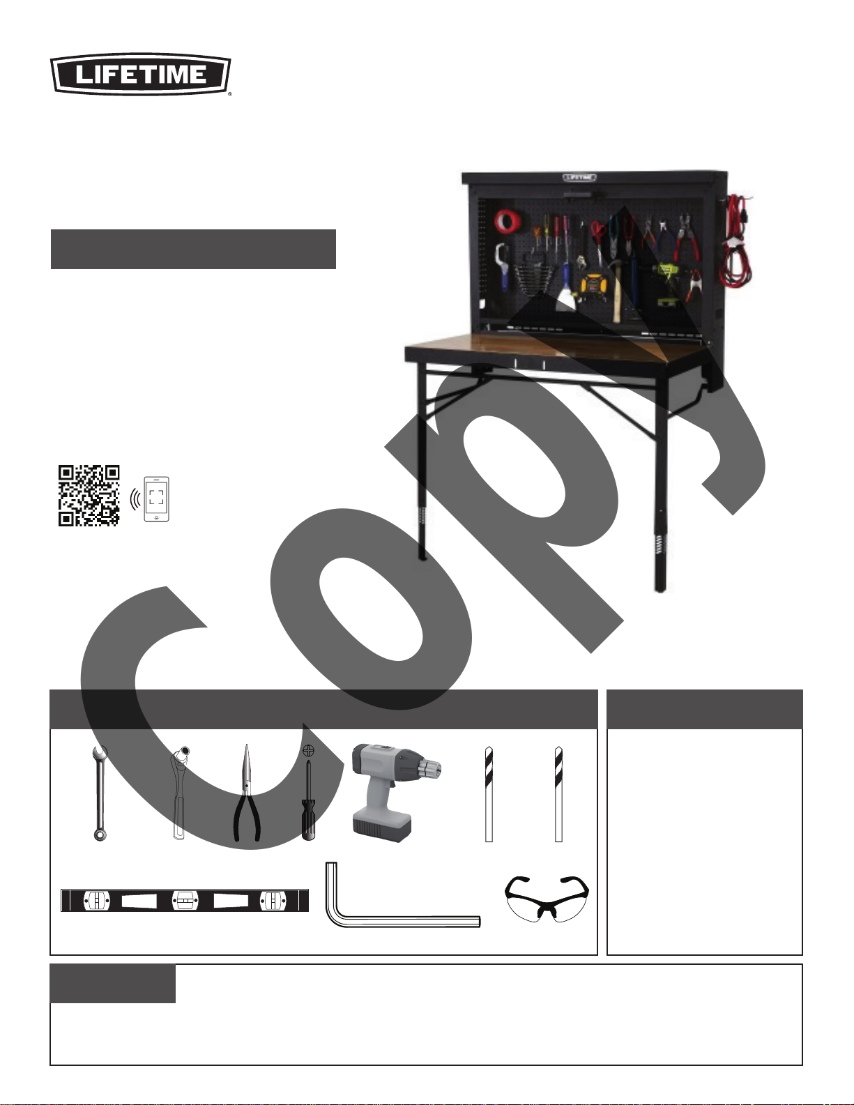
Lifetime 80421 User manual
Other Lifetime Indoor Furnishing manuals

Lifetime
Lifetime 60245 User manual

Lifetime
Lifetime 60064 User manual

Lifetime
Lifetime 80055 User manual

Lifetime
Lifetime 7060 User manual

Lifetime
Lifetime RETRO PATIO 60193 User manual

Lifetime
Lifetime 60226 User manual

Lifetime
Lifetime ADIRONDACK 60335 User manual

Lifetime
Lifetime 60030 User manual

Lifetime
Lifetime 956027 User manual

Lifetime
Lifetime 80123 User manual

Lifetime
Lifetime ADIRONDACK CHAIR 60204 User manual

Lifetime
Lifetime 60064 User manual

Lifetime
Lifetime 2129 Quick start guide

Lifetime
Lifetime 80172 User manual

Lifetime
Lifetime Honeycomb User manual

Lifetime
Lifetime WILD CHILD BACK PANEL 7526 User manual

Lifetime
Lifetime 0114 Quick start guide

Lifetime
Lifetime 81037 User manual

Lifetime
Lifetime 0130 User manual

Lifetime
Lifetime 60205 User manual


Popular Indoor Furnishing manuals by other brands


Coaster
Coaster 4799N Assembly instructions

Stor-It-All
Stor-It-All WS39MP Assembly/installation instructions

Lexicon
Lexicon 194840161868 Assembly instruction

Next
Next AMELIA NEW 462947 Assembly instructions

impekk
impekk Manual II Assembly And Instructions

Elements
Elements Ember Nightstand CEB700NSE Assembly instructions