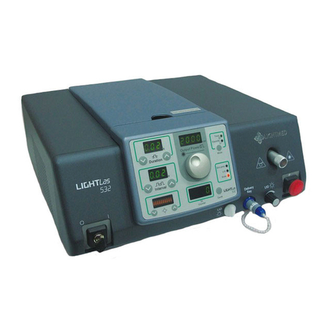
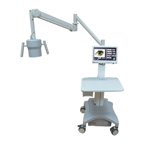
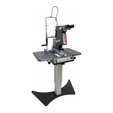
Lightmed LightLas 532 User manual

Service Manual
Multi-Wavelength Pattern
Scanning System –LightLas
532 / 670

Multi-Wavelength Pattern Scanning System - LightLas 532 / 670 - Service Manual Page 2 Rev. No 01
Service Manual
for the
Multi-Wavelength Pattern
Scanning System –LightLas
532 / 670
Directive 93/42/EEC
as amended by 2007/47/EC
Doc. No. : DC2300
Rev. No. : 01

Multi-Wavelength Pattern Scanning System - LightLas 532 / 670 - Service Manual Page 3 Rev. No 01
Service Manual for the Multi-Wavelength Pattern Scanning
System - LightLas 532 / 670
Clinicians and Doctors should ensure that they are adequately trained in the
procedures that the Multi-Wavelength Pattern Scanning System - LightLas 532 / 670
Photocoagulator Laser will be used for prior to operating the equipment.
This Service Manual should be studied and understood before proceeding to operate
the equipment on patients.
!
CAUTIONS - Use of controls or adjustments or performance of procedures
other than those specified herein may result in hazardous
radiation exposure.
CAUTIONS - Any modification to the Ophthalmic Laser will result in the necessity for
it to be reclassified
CAUTIONS - U.S. law restricts this device to sale by or on the order of a physician
This Service Manual contains confidential and proprietary information of the
Manufacturer.
Manufactured by: LightMed Corporation, No.1-1, Ln. 1, Pao-An St. Sec. 3,Shulin
Dist., New Taipei City 23861, Taiwan
USA Address: 1030 Calle Cordillera, Suite 101, San Clemente, CA 92673
Tel No.: 949-218-9555 Fax No.: 949-218-9556
Copyright ©LightMed Corporation
REPEC
EU Representative: Medical Device Safety Service GmbH
Schiffgraben 41, 30175 Hannover, Germany
Document Title:
Service Manual for the Multi-Wavelength Pattern Scanning
System - LightLas 532 / 670
Document Number:
DC2300
Document Revision History:
DRAFT
October 2012
Draft prepared

Multi-Wavelength Pattern Scanning System - LightLas 532 / 670 - Service Manual Page 4 Rev. No 01

Multi-Wavelength Pattern Scanning System - LightLas 532 / 670 - Service Manual Page 5 Rev. No 01
Table of Contents
Section 1 INTRODUCTION ..................................................................................................10
Section 2 SAFETY ................................................................................................................10
2.1 Product Classifications........................................................................................10
2.2 Warnings and Precautions...................................................................................11
2.3 Optical Hazards ................................................................................................... 12
2.3.1 Nominal Ocular Hazard Distance (NOHD)................................................ 13
2.3.2 Avoid Exposure to Laser beams...............................................................14
2.4 Electrical Hazards................................................................................................14
2.5 Safety Controls and Features..............................................................................14
Section 3 PRODUCT SPECIFICATIONS ................................................................................ 15
3.1 Multi-Wavelength Pattern Scanning System - LightLas 532 / 670 gth System Specification …….……15
3.2 CSO SL980 and SL990 Slit lamp Specifications...................................................18
Section 4 SYSTEM SETUP ...................................................................................................19
4.1 Introduction .......................................................................................................18
4.2 Unpacking and Receiving Inspection ............................................................20
4.3 Tool andEquipment .......................................................................21
4.4 Preparation ......................................................................................................22
A. System Table Top / Motorized Stand ...................................................23
B. LDU Systems / LCD System / Console / Footswitch / Accessories ...........28
4.5Final Verification / Checkout …....................................................................37
A. Integrated Slit lamp LDU ........................................................................37
B. Laser Indirect Ophthaloscope (Optional) ..............................................38
C. Endoprobes (Optional) ...........................................................................40
4.6 Integrated System Initialization and Validation ......................................…......41
A. LCD / Console Validation .........................................................................41
B. Console Control Panel and Aiming Integrity Validation .........................41
C. Pattern Scan Control Validation .............................................................43
D. Micro Joystick Movement Validation ......................................................43
E. Remote Control Validation (Optional) ...................................................43
Section 5 SYSTEM OVERVIEW............................................................................................ 50
5.1 General Operating Theory .................................................................................. 50
5.2 Theory of Operation ...........................................................................................53
5.3 System Subassemblies / Components.................................................................54
A. Laser Console Internal Modules ..............................................................55
B. LCD / Remote Control Interface Module .................................................65
C. LDU Systems ............................................................................................66
Section 6 REPAIRING PROCEDURES.................................................................................. 70
6.1 Repairing Procedures ........................................................................................ 70

Multi-Wavelength Pattern Scanning System - LightLas 532 / 670 - Service Manual Page 6 Rev. No 01
A. Microprocessor PCB Replacement .........................................................71
B. DC / DC Main PCB Replacement .............................................................72
C. DC Power Supply Module Replacement ...............................................73
Section 7 CALIBRATION / ALIGNMENT PROCEDURES ................................................74
7.1 Truscan Laser Power and Detector Calibration Procedures ........................74
A. 532nm Power Calibration Procedures (Port 1 / Port 2) .........................75
B. Software Calibration for All Different Power Range (100 - 2000mW) .78
C. 532nm Power Display Calibration Procedures (Port 1 / 2) ...................80
D. Software Calibration for All Different Power Range (50 - 2000mW) ...82
E. 670nm Power Calibration Procedures (Port 1) .....................................83
F. Software Calibration for All Different Power Range (100 - 700mW) ...86
G. 670nm Power Detector Procedures (Port 1) ........................................88
H. Software Calibration for All Different Power Range (50 - 700mW) for
Port 1 ...................................................................................................90
7.2 Aiming Spot Position Realignment Procedures ..........................................93
A. Fine Tuning ..............................................................................93
B. Coarse Tuning ......................................................................................95
C. Aiming Spot Stability Realignment Procedures (X / Y Axis) .................99
D. Spot Size Realignment Procedures (50 - 1000um) ..............................101
7.3 Slit Lamp Realignment Procedures ...........................................................102
7.4 Aiming Intensity Realignment Procedures .................................................103
A. Aiming VR Intensity Adjustment .........................................................103
B. Aiming Realignment Procedures .........................................................103
Section 8 MAINTENANCE ...........................................................................................106
8.1 Operator / User Maintenance …………………………………………….106
8.2 Laser Beam Alignment Check …………………………………………….107
8.3 System Output Power Checking Procedure ……………………………..108
8.4 Transmission Rechecking Process ..............................................................109
Section 9 TROUBLESHOOTING ...................................................................................109
9.1 Symptom …………………………………………………………………..111
9.2 Warning …………………………………………………………………...113
A. LCD Warning ..........................................................................................113
B. Remote Control Warning .....................................................................119
9.3 Error Codes ……………………………………………………………..120
Section 10 SOFTWAR UPGRADING PROCEDURES …………………………….124
10.1 Introduction ................................................................................................124
10.2 Preparation .................................................................................................124
10.3 Driver Software Downloading Procedures ................................................124
10.4 Software Installation Procedures ................................................................126
A. Window 7.0 or Above ..........................................................................126
B. Window XP ...........................................................................................131

Multi-Wavelength Pattern Scanning System - LightLas 532 / 670 - Service Manual Page 7 Rev. No 01
10.5 Configuration Procedures ........................................................133
10.6 Downloading Procedures. .........................................................................135
A. Console (MCU1) ....................................................................................135
B. Console (MCU2) ...................................................................................136
C. Re mote Control Downloading ................................ ...136
Section 11 WARRANTY TERMS .......................................................137

Multi-Wavelength Pattern Scanning System - LightLas 532 / 670 - Service Manual Page 8 Rev. No 01
LIST OF DRAWINGS / FIGURES
Figure
Description
Page
4.1
Integrated Slit lamp LDU Packing
21
4.2
Portable Carry Cases for Console and LDU’s
21
4.3
Inter-power Connection (Left hand side)
25
4.4
Slit lamp with Power Plugs Facing Each Other
25
4.5(a)
Rear View Box Connection
26
4.5(b)
Removal Fuse Socket
26
4.5(c)
Removal Fuse
27
4.5(d)
Voltage Setting Verification and Reinsert Back Process
27
4.6
Final Assembled Product and Verification Recheck
28
4.7
Slit lamp Packaging Ass'y
30
4.8
Assembled Upper and Lower Housings Screw
31
4.9
Completed Assembling Upper and Lower Housing Ass'y
31
4.10
Cabling Stuffed Underneath of Table Top's Cabling Gutter
32
4.11(a)
Slit lamp Arm Ready for Delivering Housing
32
4.11(b)
Fitting Delivering Housing to the Slit lamp and Securing it
33
4.12
Mounting Chinrest Ass'y and Fitting Delivery Fiber to Truscan
Aperture
33
4.13(a)
Hang console and plug in all the front panel connections
34
4.13(b)
Console Rear End Connections
34
4.14
Arm rest installed
35
4.15(a)
Clamp down the LCD Panel Holder in the middle of the gutter
35
4.15(b)
Organize the two control panel cablings and ready to fit the LCD
36
4.15(c)
Complete securing four holding screws behind the LCD panel and
two cablings connected
36
4.16(a)
Software System boot up
37
4.16(b)
System Ready to operate
37
4.17(a)
Fiber and Delivery Key fitted to Console Front Panel
39
4.17(b)
Fiber tips cleaning
39
4.17(c)
LCD LIO Intensity Control Knob
40
4.17(d)
LIO Intensity Control Knob
40
4.18
Endoprobe plug installation
41
4.19(a)
Front End Connection
45
4.19(b)
Rear End Connection
45

Multi-Wavelength Pattern Scanning System - LightLas 532 / 670 - Service Manual Page 9 Rev. No 01
Figure
Description
Page
4.20(a)
System boot up sequential display 1
46
4.20(b)
System boot up sequential display 2
46
4.20(c)
System boot up sequential display 3
46
4.21
Initial Aiming Intensity Verification
46
5.1
LCD and Console System Block Diagram
53
5.2
Truscan Console Layout Diagram
54
7.1
Y-Axis Pattern Screen Shot
101
7.2
X-Axis Pattern Screen Shot
101
9.1(a)
Sample of Error code display
119
9.1(b)
Sample of Remote Control Error code display
119
Record Sheet
Installation Record Sheet
47-48
Primary Power Calibration Record Sheet
90
Secondary Power Calibration Record Sheet
91
Transmission Checking Record Sheet
109
Appendix
Appendix I Accessories / Parts Listing Detailed
136- 137
Appendix II Console Wiring Diagram
138

Multi-Wavelength Pattern Scanning System - LightLas 532 / 670 - Service Manual Page 10 Rev. No 01
Section 1 Introduction
This manual is intended to provide the operator with an overview of the operation
and safety requirements for the Multi-Wavelength Pattern Scanning System -
LightLas 532 / 670 Ophthalmic Laser. This manual is not intended to provide
instructions on actual treatment procedures and it is expected that users will have
undertaken training prior to using the equipment.
The Manufacturer and Distribution organization assume no liability through the use
of this Laser system.
All care has been taken in the preparation and checking of this manual however there
is no guarantee provided that all information is correct. The information provided in
this manual is subject to change without notice.
Only approved or authorized accessories may be used in the Multi-Wavelength
Pattern Scanning System - LightLas 532 / 670 Ophthalmic Laser. The Manufacturer
and Distribution organization shall not be held liable or responsible for damages or
injury caused as a result of using non-approved accessories. This includes all Optical
Fiber systems, Laser Delivery Units, Safety Filters, Safety Glasses and Table units.
All maintenance and service work must be carried out by authorized and trained
service agents and only those procedures outlined in the operator and service
manual are allowed. Any service work carried out by unauthorized persons will void
all warranties.
No circuit diagrams or component part lists are to be supplied for the Multi-
Wavelength Pattern Scanning System - LightLas 532 / 670 Ophthalmic Laser. If you
require technical documentation that is not provided in this manual then please
contact the manufacturer or your local distributor in writing with your reasons for
wanting them and then a copy of the service manual may be provided.
Before using the Multi-Wavelength Pattern Scanning System - LightLas 532 / 670
Photocoagulator, the operator should read this manual carefully and pay particular
attention to the sections of Safety, Operation and Maintenance.

Multi-Wavelength Pattern Scanning System - LightLas 532 / 670 - Service Manual Page 11 Rev. No 01
Section 2 Safety
This Laser system has been designed and tested to function in a safe and correct
when used as indicated in this manual.
Do not use this laser before reading and understanding completely this Operators
Manual.
It is important to remember that this laser emits high levels of visible laser radiation
which can cause permanent and irreparable eye and tissue damage. Always observe
precautions for laser safety including using warning signs, safety glasses and only
operating the laser in a treatment room that provides protection to casual observers.
2.1 Product Classifications
The Multi-Wavelength Pattern Scanning System - LightLas 532 / 670 Photocoagulator
Laser is a Class IV laser product as specified in the standard IEC60825-1 (2007) and the
USA 21 CFR’s 1040.10, 1040.11.
The Multi-Wavelength Pattern Scanning System - LightLas 532 / 670 Photocoagulator
Laser is classified as Class I Type B Electromedical equipment as specified in the
IEC60601-1 standard.
The Multi-Wavelength Pattern Scanning System - LightLas 532 / 670 Photocoagulator
Laser is classified as a Class II device according to the FDA CFR21 regulations.
The Multi-Wavelength Pattern Scanning System - LightLas 532 / 670 Photocoagulator
Laser is classified as a Class II Type B Medical Device according to the MDD 93/42/EEC
(as amended by 2007/47/EC).
The Multi-Wavelength Pattern Scanning System - LightLas 532 / 670 has been designed to
comply with the following standards:
Laser standards
IEC 60825-1 (2007)
USA 21 CFR 1040.10, 1040.11 (1997)
IEC60601-2-22 (1995)
Electrical standards
IEC60601-1 (1988) + A1(1991) and A2(1995)
IEC60601-1-1 (2000)
IEC60601-1-2 (2007)
USA UL 2601
JIS T1001 (1992) and T1002 (1992)

Multi-Wavelength Pattern Scanning System - LightLas 532 / 670 - Service Manual Page 12 Rev. No 01
Others
MDD 93/42/EEC (as amended by 2007/47/EC)
IEC60601-1-4 (1996) + A1 (1999)
ISO14971 (2007)
2.2 Warnings and Precautions
The following warnings and precautions apply to the Multi-Wavelength Pattern
Scanning System - LightLas 532 / 670 and should be observed by all users at all time:
DO NOT look directly into or at the laser beam or at specular laser reflections
since direct and reflected laser light from the laser aperture can cause
permanent eye injury.
DO NOT operate the laser unless observers are using the correct protective
eyewear. The protective eyewear must have an optical density of OD4 or
more at 532 nanometers wavelength. This information must be present on
the eyewear.
DO NOT use objects that can readily reflect light in the vicinity of the laser
beam to avoid reflecting the beam in a hazardous manner.
DO NOT fire the Laser directly onto flammable agents or gasses as the
focused laser beam may cause ignition. There is no AP/ APG protection.
DO NOT try to service or repair the laser other than what is included in this
manual. Service should only be performed by an authorized and trained
agent of the manufacturer.
DO NOT fire the laser on a patient without first checking the operation of
the laser and verifying the optical alignment of the treatment Laser beam.
ALWAYS use the lowest power settings possible when treating a patient
with the laser and start the treatment with minimum level of power.
ALWAYS set the correct spot size and/or use the most appropriate one for
the power setting and type of procedure that is to be performed.
DO NOT put the laser into ‘TREAT’mode until ready to operate on the
patient.
DO NOT inhale any laser plume generated by the Laser during surgery.
Personnel should take an extreme measured precaution, such as wearing
surgical masks or use plume evacuation systems when a treatment is
undergoing. Caution - Laser plume may contain viable tissue particulates.
ALWAYS take particular care of the optical fibers that connect the Laser
Delivery Units to the Console to make sure they do not get damaged.

Multi-Wavelength Pattern Scanning System - LightLas 532 / 670 - Service Manual Page 13 Rev. No 01
Additional clinical warnings may be found in Section 6.1.4 of this Manual.
ALWAYS try to let the laser have its own or dedicated power outlet.
Additional items may be plugged in a Multiple Portable Socket Outlet, which
may be plugged into an additional outlet.
DO NOT use the Laser Console if the ambient temperature is outside the
range of 20 to 35°C. This temperature range is the rated operating
temperature limits where the Laser system can be guaranteed to operate
without any interruptions to normal use. Outside this range of temperature
it is possible that the Laser will generate an error condition where the word
“hold” is displayed and the system goes to Standby until the internal
temperature returns to within normal limits then the Laser can be used again
but the error condition may reoccur unless the rated temperature comes
within limits.
2.3 Optical Hazards
Guidance for the safe use of Lasers and Laser systems is found in the standard
IEC60825-1, the USA 21CFR 1040.10, 1040.11 and ANSI Z136.1 - 1986.
During normal operation of the Multi-Wavelength Pattern Scanning System - LightLas
532 / 670 the operator is protected from Laser hazards by built in optical absorption
Safety Filters. All other personnel in the area should wear protective eyewear to
eliminate the risk of eye injury occurring.
The optical density (OD) of eye protection must be greater than or equal to 4 and the
wavelength 532nm and 670nm range are also specified on it. It is shown in the
following format:
OD4+ @ 532nm / 670nm
Otherwise, the safety glasses are NOT suitable for this purpose of eye protection.
Safety Glasses are required to have the CE mark applied if used in the EU.
The Multi-Wavelength Pattern Scanning System - LightLas 532 / 670 uses a Class II
Laser Diode Aiming beam. Its wavelength range from 635 to 650 nanometers (nm)
and the maximum power output is set at the factory to be less than 1mW delivered to
the patients cornea. However it is always recommended to use the lowest aiming
beam intensity during treatments.
The Multi-Wavelength Pattern Scanning System - LightLas 532 / 670 Photocoagulator
Laser has been classified as a Class 4 and its classification specified accordingly to the
above quoted standards. This classification is also based on the Accessible Emission
Limits (AEL) as calculated according to the standards.

Multi-Wavelength Pattern Scanning System - LightLas 532 / 670 - Service Manual Page 14 Rev. No 01
2.3.1 Nominal Ocular Hazard Distance (NOHD)
The Nominal Ocular Hazard Distance (NOHD) is the distance between the equipment
and a person’s eye for which the optical power, from the equipment, entering the
dilated pupil of the person will be less than or equal to the Maximum Permissible
Exposure (MPE) as specified in the standards (i.e. less than a Class 1 Laser Output).
The calculated NOHD for the Multi-Wavelength Pattern Scanning System - LightLas
532 / 670 with different Laser Delivery Units is:
5 meters at maximum power settings for the Endoprobes
18 meters at maximum power settings and 1000m spot size for Slit lamp
Delivery Units
20 meters at maximum power settings for LIO
Therefore when the laser is in operation, all persons that are closer than these
distances to the equipment should be wearing eye protection.
Patients, where possible, should have the untreated eye covered or protected from
laser reflections.

Multi-Wavelength Pattern Scanning System - LightLas 532 / 670 - Service Manual Page 15 Rev. No 01
2.3.2 Avoid Exposure to Laser beams
Reassembly or maintenance of the laser system should only be performed by
authorized and trained personnel. The external housing of the laser system should
never be removed otherwise you or standby observers could be exposed to
dangerous levels of laser radiation and potentially lethal electrical voltages.
Eye safety filters are designed to protect physician’s eyes from back scattered laser
beams must always be used. They are integrated into the Slit lamp and LIO Delivery
Units. When using the endoprobes a separate filter that attaches to the operating
microscope must be used.
For other personnel that may be exposed to reflections or backscatter they must
wear safety glasses or goggles. In any case NEVER look directly at the treatment
laser beam as severe eye injury is likely. This means avoid looking into the aperture of
any of the laser delivery units or the console.
2.4 Electrical Hazards
The Multi-Wavelength Pattern Scanning System - LightLas 532 / 670 Photocoagulator
laser has been designed to apply the International Standards for Medical Equipment.
The laser system is designed to operate with three terminal prongs AC voltage where
the third prong pin is the earth-grounded prong.
Warning: It is not safe to operate the Multi-Wavelength Pattern Scanning System -
LightLas 532 / 670 photocoagulator laser without an earth-grounded receptacle.
There is possible risk of electric shock.
No cover or housing need to be removed by the operator or user. Only the
authorized and trained service or agent can remove the cover or housing assembly
since there is possible of exposing laser radiation and high current or voltages.

Multi-Wavelength Pattern Scanning System - LightLas 532 / 670 - Service Manual Page 16 Rev. No 01
Section 3 Production Specifications
3.1 TruScan Pattern Scanning Laser System
The following are the System Specifications for the Multi-Wavelength Pattern
Scanning System - LightLas 532 / 670 Ophthalmic Laser.
_____________________________________________________________________
A. General Console Spec.
Electrical Input
100 to 230 Vac. 50/60 Hz Single phase
Power
400VA
Fuse rating
T3.15AH250V @ 100-230Vac (Time Lag)
Temperature
Range
Transport: -10 to 70°C
Operating: 15 to 30°C
Storage: -10 to 55°C
Relative
Humidity Range
Operating: 30% - 85% non-condensing
Storage and Transport: up to 95% non-condensing
Atmospheric
pressure
Operating: 800-1060 mbar
Storage and Transport: 500-1060 mbar
Cooling System
Fan cooled and TEC’s for Laser Diode and Crystal
Dimensions
130mm(H) x 370mm(W) x 330mm(D)
Weight
13 Kg (System) 20 Kg (Packed)
Treatment Laser
Laser Type
Diode Pumped Frequency
Doubled YAG
Diode Laser
Wavelength
532nm
670nm
Mode of
Operation
CW
Power
Output
2 W Maximum to Patients
Cornea Power from Delivery
unit laser aperture displayed
on Remote Display Panel
700mW Maximum to Patients Cornea.
Power from Delivery unit laser aperture
displayed on Remote Display Panel
Power
Adjustment
Variable from 0.05 to 2.0 W
Variable from 0.05 to 700 mW
Exposure
Duration
0.01, 0.02, 0.03, 0.04, 0.05, 0.06, 0.08, 0.1, 0.15 then from 0.2 to 3.0s in
0.1 sec. intervals
Repeat
Interval
Selectable from 0.01 to 3.0s and equal to or greater than exposure
duration in same discrete steps as duration
Doctor Safety
OD4

Multi-Wavelength Pattern Scanning System - LightLas 532 / 670 - Service Manual Page 17 Rev. No 01
Filter
Safety Class
Class 4
Power Display
accuracy
Better than +/-20% of actual
Beam
Divergence
< 0.2 NA
Aiming Laser
Laser Type
Red Laser Diode
Wavelength
635–650 nm (Red)
Mode of
Operation
CW
Output power
Maximum of 1.0mW
Power
Adjustment
Continuously variable
Safety Class
Class 2
B. Laser Delivery Units
Integrated Slitlamp LDU with TruScan
Slitlamp model
CSO Model SL980 (K992836)
Spot Sizes
50m ~1000 m continuously selectable on Zoom assembly of
Delivery unit
Focus plane
All spot sizes Parfocal to Slitlamp focus plane
Fiber Length
2 m
Mounting
Direct to Slitlamp housing
Safety Filter
Fixed filter OD 4 @ 532nm and 670nm
Beam Divergence
Cone angle of 20°
Laser Indirect Ophthalmoscope (LIO)
Indirect model
Keeler All Pupil II
Retinal Spot size
300µm nominal at focus with 20D Laser Lens
Illumination
power
From Laser Console. Internal PSU allows intensity adjustment.
Connector is on Console Front Panel
Fiber length
3 m
Weight
Less than 500gms without laser attachment
Safety Filter
Fixed filter OD 4

Multi-Wavelength Pattern Scanning System - LightLas 532 / 670 - Service Manual Page 18 Rev. No 01
Beam Divergence
Cone angle 20°
Endo-ocular Probes
Probe Types
Straight, Curved and Aspirating
Fiber Length
3 m
Safety Filters
OD 4 in housing for installation to Operating Microscope before
Laser can be fired
Sterile
Sterilized by Ethylene Oxide and packed as Single use devices ready
for use
Beam
Divergence
0.2 NA
Lightlas with TruScan
Slitlamp model
CSO Model SL980 (K992836)
Spot Sizes
50m ~1000 m continuously selectable on Zoom assembly of
Delivery unit
Focus plane
All spot sizes Parfocal to Slitlamp focus plane
Fiber Length
2 m
Mounting
Direct to Slitlamp housing
Safety Filter
Fixed filter OD 4 @ 532nm and 670nm
Beam Divergence
Cone angle of 20°
Pattern Scanning
Single, Line, Square (2x2, 3x3, 4x4, 5x5), Macular Arc (single, double,
triple 1/4, 1/2, 3/4), Circle and Triangle –Spot width, density and 360
rotation available for each pattern.
C. Accessories
Remote Control (Optional)
Dimension
Weight
Trolley (Optional)
Dimension
Weight

Multi-Wavelength Pattern Scanning System - LightLas 532 / 670 - Service Manual Page 19 Rev. No 01
3.2 CSO SL980 Slit lamp Specifications
The following are the Slit lamp Specifications for the CSO SL980 Slit lamps that is
accompanied with the Multi-Wavelength Pattern Scanning System - LightLas 532 / 670
Photocoagulator Laser System. The SL980 is a Zeiss clone and uses an illumination
source below the viewing path.
Microscope : Galilean
Magnification Set : 5 Step Drum Rotation
Eyepiece : 12.5X
Magnification Ratio : 6X, 10X, 16X, 25X, 40X
PD Range : 48.5-80mm
Diopter Adjustment : +/-8
Slit Illumination : 6V 20W Halogen Lamp
Slit Width : 0-14mm
Slit Length : 1.8 –12mm
Slit Apertures : 0.3, 5.5, 9, 14mm
Slit Angles : 0°- 180°
Filters : Red Free, Heat Absorbing, Cobalt Blue
Movement Ranges
Longitudinal (In/Out) : 113mm
Lateral (Left/Right) : 108mm
Vertical (Up/Down) : 35mm
Fine movement range : 10mm
Chin Rest Range : 70mm

Multi-Wavelength Pattern Scanning System - LightLas 532 / 670 - Service Manual Page 20 Rev. No 01
Section 4 System Setup
4.1 Introduction
It is strongly recommended that the manufacturer or its authorized agent install the
Multi-Wavelength Pattern Scanning System - LightLas 532 / 670 at the operator site to
ensure that the system is operating correctly, aligned and calibrated according to
specification. After this initial installation it is the operator’s responsibility to ensure
the laser system is operating correctly whenever the laser is moved or relocated.
The following procedures should be followed in order to successfully install the laser
system. The checklist and report form should be completed and a copy sent to the
manufacturer. In the event that the report is not sent to the manufacturer then the
manufacturer reserves the right to decline any warranty claims that may be
forthcoming.
The installer should also retain a copy and the customer may keep a copy too.
All precautions care must be taken when installing the Multi-Wavelength Pattern
Scanning System - LightLas 532 / 670 to ensure that you or others are not exposed to
any hazardous laser radiation. Always wear laser safety glasses suitable for the
532nm wavelength to protect your eyes.
Requirements
1. 100-230 Volts, 50 or 60Hz AC mains power supply with an earth connection.
This is a single-phase outlet capable of delivering up to 400 Watts.
2. A motorized stand that the Table provided with the Slit lamp can be fitted
to is required if one was not purchased with the Laser system. Ensure the
Table is fitted securely to the Stand using the supplied screws.
3. A mains power cable is supplied but the connector may not suit the outlet
available so it is advisable to have a spare locally compatible cable available.
The Cable assembly must be CE approved for EU Countries.
4. A suitable room to place the Laser System in that provides for a safe
working environment is required. As with other ophthalmic equipment a
dimly lit room is preferred.
5. The Laser System has the facility to connect a remote door interlock to the
Laser treatment room. If this option is required then the customer must
organize this with an electrician and the manufacturer or authorized agent
can provide instructions on how to connect to the Laser System. The Laser
System is provided with a Bypass plug in the event that this option is not
installed. This plug is referred to as the “Interlock Key” and must be
inserted into the back of the console, in order for the system to operate.
Other manuals for LightLas 532
2
This manual suits for next models
2
Table of contents
Other Lightmed Medical Equipment manuals
Popular Medical Equipment manuals by other brands

Sunrise Medical
Sunrise Medical Deep Contour Cushion J2 User instruction manual & warranty

Otto Bock
Otto Bock ScoutCrawler Instructions for use

inhealth
inhealth Blom-Singer Indwelling TEP Occluder Instructions for use

Redsense Medical
Redsense Medical Alarm Unit Instructions for use

Vitalograph
Vitalograph Micro instructions

Koven
Koven FASTSphyg Operation manual & reference guide