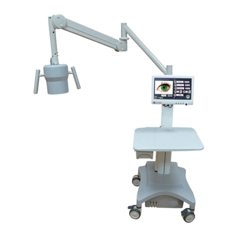
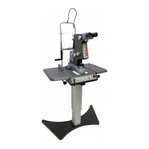
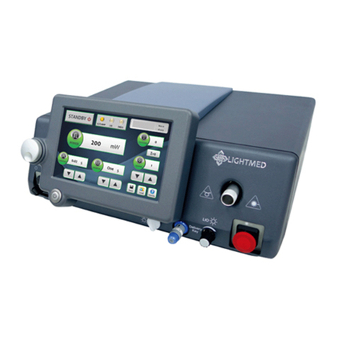
Lightmed LightLas 532/670 User manual

Operator Manual
Multi-Wavelength Pattern
Scanning System –LightLas
532 / 670

Multi-Wavelength Pattern Scanning System - LightLas 532 / 670 –Operators Manual Rev. No 01
Page 1 of 126
Operator Manual
for the
Multi-Wavelength Pattern
Scanning System - LightLas
532 / 670
Directive 93/42/EEC
as amended by 2007/47/EC
Doc. No. : DC1800
Rev. No. : 01

Multi-Wavelength Pattern Scanning System - LightLas 532 / 670 –Operators Manual Rev. No 01
Page 2 of 126
Operator Manual for the Multi-Wavelength Pattern Scanning
System –LightLas 532 / 670
Clinicians and Doctors should ensure that they are adequately trained in the
procedures that the Multi-Wavelength Pattern Scanning System - LightLas 532 / 670
Photocoagulator Laser will be used for prior to operating the equipment.
This Service Manual should be studied and understood before proceeding to operate
the equipment on patients.
!
CAUTIONS - Use of controls or adjustments or performance of procedures other
than those specified herein may result in hazardous radiation exposure.
CAUTIONS - Any modification to the Ophthalmic Laser will result in the necessity for
it to be reclassified
CAUTIONS - U.S. law restricts this device to sale by or on the order of a physician
This Service Manual contains confidential and proprietary information of the
Manufacturer.
Manufactured by: LightMed Corporation, No.1-1, Ln. 1, Pao-An St. Sec. 3,Shulin
Dist., New Taipei City 23861, Taiwan
USA Address: 1030 Calle Cordillera, Suite 101, San Clemente, CA 92673
Tel No.: 949-218-9555 Fax No.: 949-218-9556
Copyright ©LightMed Corporation
REPEC
EU Representative: Medical Device Safety Service GmbH
Schiffgraben 41, 30175 Hannover, Germany
Document Title:
Operator Manual for the Multi-Wavelength Pattern Scanning
System - LightLas 532 / 670
Document Number:
DC1800
Document Revision History:
DRAFT
October 2012
Draft prepared

Multi-Wavelength Pattern Scanning System - LightLas 532 / 670 –Operators Manual Rev. No 01
Page 3 of 126

Multi-Wavelength Pattern Scanning System - LightLas 532 / 670 –Operators Manual Rev. No 01
Page 4 of 126
Table of Contents
Section 1 INTRODUCTION ……………………………………………………………..8
Section 2 SAFETY.………………………………………………………………………9
2.1 Product Classifications ….…………………………………………………………... 9
2.2 Warnings and Precautions …………………………………………………………. 10
2.3 Optical Hazards ……………………………………………………………………..12
2.3.1 Nominal Ocular Hazard Distance (NOHD)....................................................12
2.4 Electrical Hazards ……………………………………………………………………13
2.5 Safety Controls and Features ……………………………………………………….14
2.6 Product Labeling …………………………………………………………………….18
2.61 Console system............................................................................................... 18
2.62 Integrated Slit lamp LDU ..............................................................................20
2.63 Laser Indirect Ophthalmoscope LDU ........................................................... 22
Section 3 PRODUCT SPECIFICATIONS ……………………………...………………..23
3.1 Introduction ………………………………………………………………………… 23
3.1.1 Console Laser System ……………………………………………………...24
3.2.1 Laser Delivery Unit (LDU) ………………………………………………….25
3.3.1 Accessories …………………………………………………………………26
3.2 CSO SL980 Slit lamp Specifications …………………………………...…………...26
Section 4 PRINCIPLES OF OPERATION ….………………………………………..27
4.1 General Description ………………………………………………………………..27
4.2 Laser Console ……………………......……………………………………………..35
4.3 LCD Control Panel Display Screen……………………………………….................41
4.3.1 Console Control Screen…………………………………………………39
4.3.2 Pattern Control Screen ..............................................................................39
4.4. Remote Control Panel ............................................................................................. 53
4.5 Truscan Integrated into CSO model SL980………………………………57
A. Integrated CSO SL980 Controls Breakdown ……………………………59
4.6 Laser Indirect Ophthalmoscope (LIO).…………………………………...……60
Section 5 Installation………….…………………………………………………...63
5.1 Introduction ………………………………………………………………………...63
5.2 Unpacking and Receiving Inspection ……………………………………………...65
5.3 Tools and Equipment ………………………………………………………………66
5.4 Preparation …………………………………………………………...…………….67
5.4.1 System components …..…………..…………………………………… 67
A. System table top and motorized stand ………………………. ....……… 69
B. LDU system / LCD System / Footswitch / Accessories…..…… ... ………. 74
5.5 Final Verification / Checkout ……………………………………………………… 82
A. Slit lamp Integrity Rechecks ………………………………………………82

Multi-Wavelength Pattern Scanning System - LightLas 532 / 670 –Operators Manual Rev. No 01
Page 5 of 126
B. Laser Indirect Ophthalmoscope (Optional) …………………………83
C. Endoprobe (Optional) ………………………………………………86
5.6 Integrated System Initialization and Validation …………….……………………..82
A. LCD / Console Validation ……………………………………………..87
B. Console Control Panel and Aiming Intensity Validation ……………87
C . P a t t e r n S c a n C o n t r o l V a l i d a t i o n ……………89
D . M i c r o J o y s t i c k M o v e m e n t V a l i d a t i o n ……89
E . R e m o t e C o n t r o l V a l i d a t i o n ( O p t i o n a l ) ……89
Section 6 CLINICAL USE…………………………………………………………93
6.1 Different types of LDUs Indication / Contraindication Use ……………………….94
6.1.1 Slit lamp Delivery Unit …………………………………………………...94
6.1.2 Laser Indirect Ophthalmoscope (LIO) …………………………………….94
6.1.3 Endoprobe devices ………………………………………………………...95
6.2 General Warnings …………………………………………………………………...97
6.3 Possible side-effect or adverse reactions …………………………………………..99
Section 7 MAINTENANCE…………………………………………………………100
7.1 Operator / User Maintenance ……………………………………………………...100
7.2 Laser Beam Alignment Check ……………………………………………………...101
7.3 System Output Power Checking Procedure ……………………………………...102
Section 8 TROUBLESHOOTING………………………………………………………104
8.1 Symptom .................………………………………………………………………..104
8.2 Warning …………………………………………………………………………….106
A. LCD Control Warning Only …………………………………………………..105
B. Remote Control Warning Only ……………………………………………...112
8.3 Error Codes …………………………………………………………………………113
Section 9 European Community Issues……………………………………..117
Section 10 EMC Test Tables…………………………………………………….119

Multi-Wavelength Pattern Scanning System - LightLas 532 / 670 –Operators Manual Rev. No 01
Page 6 of 126
LIST OF DRAWINGS / FIGURES
Figure
Description
Page
2.1
Safety Controls
14
2.2(a)
Laser Console Labels
18
2.2(b)
Laser Console Labels
19
2.4(a)
Integrated Slit lamp LDU with Labels (RH side)
20
2.4(b)
Integrated Slit lamp LDU with Labels (LH side)
21
2.5
LIO LDU with Labels
22
4.1
System software start up screen shot
31
4.2
System software boot up ok and system is "Standby" mode
31
4.3
System software is ready to shutdown
34
4.4
Laser Console Connection / Controls
35
4.5
Screen shot display
38
4.6
Console Control Screen
39
4.7
Pattern Scan Control Screen Shot
43
4.8
Remote Control Panel Breakdown
52
4.9
Integrated Slit lamp LDU Controls
56
4.10(a)
SL980 Slit lamp Parts List and Controls
58
4.10(b)
SL980 Slit lamp Parts List and Controls
59
4.11(a)
Front View of LIO LDU Controls
60
4.11(b)
Top View of LIO LDU Controls
60
5.1
Integrated Slit lamp LDU Packing
65
5.2
Portable Carry Cases for Console and LDU’s
65
5.3
Inter-power Connection (Left hand side)
69
5.4
Slit lamp with Power Plugs Facing Each Other
69
5.5(a)
Rear View Box Connection
70
5.5(b)
Removal Fuse Socket
70
5.5(c)
Removal Fuse
71
5.5(d)
Voltage Setting Verification and Reinsert Back Process
71
5.6
Final Assembled Product and Verification Recheck
72
5.7
Slit lamp Packaging Ass'y
74
5.8
Assembled Upper and Lower Housings Screw
75
5.9
Completed Assembling Upper and Lower Housing Ass'y
75
5.10
Cabling Stuffed Underneath of Table Top's Cabling Gutter
76
5.11(a)
Slit lamp Arm Ready for Delivering Housing
76
5.11(b)
Fitting Delivering Housing to the Slit lamp and Securing it
77
5.12
Mounting Chinrest Ass'y and Fitting Delivery Fiber to Truscan Aperture
77

Multi-Wavelength Pattern Scanning System - LightLas 532 / 670 –Operators Manual Rev. No 01
Page 7 of 126
Figure
Description
Page
5.13(a)
Hang console and plug in all the front panel connections
78
5.13(b)
Console Rear End Connections
78
5.14
Arm rest installed
79
5.15(a)
Clamp down the LCD Panel Holder in the middle of the gutter
79
5.15(b)
Organize the two control panel cablings and ready to fit the LCD
80
5.15(c)
Complete securing four holding screws behind the LCD panel and
two cablings connected
80
5.16(a)
Software System boot up
81
5.16(b)
System Ready to operate
81
5.17(a)
Fiber and Delivery Key fitted to Console Front Panel
83
5.17(b)
Fiber tips cleaning
83
5.17(c)
LCD LIO Intensity Control Knob
84
5.17(d)
LIO Intensity Control Knob
84
5.18
Endoprobe plug installation
85
5.19(a)
Front End Connection
89
5.19(b)
Rear End Connection
89
5.20(a)
System boot up sequential display 1
90
5.20(b)
System boot up sequential display 2
90
5.20(c)
System boot up sequential display 3
90
5.21
Initial Aiming Intensity Verification
90
8.1(a)
Sample of Error code display
112
8.1(b)
Sample of Remote Control Error code display
115
Record Sheet
Installation Record Sheet
91-92
Power Meter Calibration Record Sheet
102
Appendix
Appendix I (Accessories / Parts Listing Detailed)
124- 125

Multi-Wavelength Pattern Scanning System - LightLas 532 / 670 –Operators Manual Rev. No 01
Page 8 of 126
Section 1 INTRODUCTION
This manual is intended to provide the operator with an overview of the operation
and safety requirements for the Multi-Wavelength Pattern Scanning System -
LightLas 532 / 670 Ophthalmic Laser. This manual is not intended to provide
instructions on actual treatment procedures and it is expected that users will have
undertaken training prior to using the equipment.
The Manufacturer and Distribution organization assume no liability through the use
of this Laser system.
All care has been taken in the preparation and checking of this manual however there
is no guarantee provided that all information is correct. The information provided in
this manual is subject to change without notice.
Only approved or authorized accessories may be used in the Multi-Wavelength
Pattern Scanning System - LightLas 532 / 670. The Manufacturer and Distribution
organization shall not be held liable or responsible for damages or injury caused as a
result of using non-approved accessories. This includes all Optical Fiber systems,
Laser Delivery Units, Safety Filters, Safety Glasses and Table units.
All maintenance and service work must be carried out by authorized and trained
service agents and only those procedures outlined in the operator and service
manual are allowed. Any service work carried out by unauthorized persons will void
all warranties.
No circuit diagrams or component part lists are to be supplied for the Multi-
Wavelength Pattern Scanning System - LightLas 532 / 670. If you require technical
documentation that is not provided in this manual then please contact the
manufacturer or your local distributor in writing with your reasons for wanting them
and then a copy of the service manual may be provided.
Before using the Multi-Wavelength Pattern Scanning System - LightLas 532 / 670
Photocoagulator the operator should read this manual carefully and pay particular
attention to the sections of Safety, Operation and Maintenance.

Multi-Wavelength Pattern Scanning System - LightLas 532 / 670 –Operators Manual Rev. No 01
Page 9 of 126
Section 2 SAFETY
This Laser system has been designed and tested to function in a safe and correct
when used as indicated in this manual.
Do not use this laser before reading and understanding completely this Operators
Manual.
It is important to remember that this laser emits high levels of visible laser radiation
which can cause permanent and irreparable eye and tissue damage. Always observe
precautions for laser safety including using warning signs, safety glasses and only
operating the laser in a treatment room that provides protection to casual observers.
2.1 Product Classifications
The Multi-Wavelength Pattern Scanning System - LightLas 532 / 670 Photocoagulator
Laser is a Class IV laser product as specified in the standard IEC60825-1 (2007) and the
USA 21 CFR’s 1040.10, 1040.11.
The Multi-Wavelength Pattern Scanning System - LightLas 532 / 670 Photocoagulator
Laser is classified as Class I Type B Electromedical equipment as specified in the
IEC60601-1 standard.
The Multi-Wavelength Pattern Scanning System - LightLas 532 / 670 Photocoagulator
Laser is classified as a Class II device according to the FDA CFR21 regulations.
The Multi-Wavelength Pattern Scanning System - LightLas 532 / 670 Photocoagulator
Laser is classified as a Class II Type B Medical Device according to the MDD 93/42/EEC
(as amended by 2007/47/EC).
The Multi-Wavelength Pattern Scanning System - LightLas 532 / 670 has been designed to
comply with the following standards:
Laser standards
IEC 60825-1 (2007)
USA 21 CFR 1040.10, 1040.11 (1997)
IEC60601-2-22 (1995)
Electrical standards
IEC60601-1 (1988) + A1(1991) and A2(1995)
IEC60601-1-1 (2000)
IEC60601-1-2 (2007)
USA UL 2601
JIS T1001 (1992) and T1002 (1992)

Multi-Wavelength Pattern Scanning System - LightLas 532 / 670 –Operators Manual Rev. No 01
Page 10 of 126
Others
MDD 93/42/EEC (as amended by 2007/47/EC)
IEC60601-1-4 (1996) + A1(1999)
ISO14971 (2007)
2.2 Warnings and Precautions
The following warnings and precautions apply to the Multi-Wavelength Pattern
Scanning System - LightLas 532 / 670 Laser System and should be observed by all
users at all time:
DO NOT look directly into or at the laser beam or at specular laser reflections
since direct and reflected laser light from the laser aperture can cause
permanent eye injury.
DO NOT operate the laser unless observers are using the correct protective
eyewear. The protective eyewear must have an optical density of OD4 or
more at 532 nanometers wavelength. This information must be present on
the eyewear.
DO NOT use objects that can readily reflect light in the vicinity of the laser
beam to avoid reflecting the beam in a hazardous manner.
DO NOT fire the Laser directly onto flammable agents or gasses as the
focused laser beam may cause ignition. There is no AP/ APG protection.
DO NOT try to service or repair the laser other than what is included in this
manual. Service should only be performed by an authorized and trained
agent of the manufacturer.
DO NOT fire the laser on a patient without first checking the operation of
the laser and verifying the optical alignment of the treatment Laser beam.
ALWAYS use the lowest power settings possible when treating a patient
with the laser and start the treatment with minimum level of power.
ALWAYS set the correct spot size and/or use the most appropriate one for
the power setting and type of procedure that is to be performed.
DO NOT put the laser into ‘TREAT’mode until ready to operate on the
patient.
DO NOT inhale any laser plume generated by the Laser during surgery.
Personnel should take an extreme measured precaution, such as wearing
surgical masks or use plume evacuation systems when a treatment is
undergoing. Caution - Laser plume may contain viable tissue particulates.
ALWAYS take particular care of the optical fibers that connect the Laser

Multi-Wavelength Pattern Scanning System - LightLas 532 / 670 –Operators Manual Rev. No 01
Page 11 of 126
Delivery Units to the Console to make sure they do not get damaged.
Additional clinical warnings may be found in Section 6.1.4 of this Manual.
ALWAYS try to let the laser have its own or dedicated power outlet.
Additional items may be plugged in a Multiple Portable Socket Outlet, which
may be plugged into an additional outlet.
DO NOT use the Laser Console if the ambient temperature is outside the
range of 20 to 35°C. This temperature range is the rated operating
temperature limits where the Laser system can be guaranteed to operate
without any interruptions to normal use. Outside this range of temperature
it is possible that the Laser will generate an error condition where the word
“hold” is displayed and the system goes to Standby until the internal
temperature returns to within normal limits then the Laser can be used again
but the error condition may reoccur unless the rated temperature comes
within limits.
2.3 Optical Hazards
Guidance for the safe use of Lasers and Laser systems is found in the standard
IEC60825-1, the USA 21CFR 1040.10, 1040.11 and ANSI Z136.1 - 1986.
During normal operation of the Multi-Wavelength Pattern Scanning System - LightLas
532 / 670 the operator is protected from Laser hazards by built in optical absorption
Safety Filters. All other personnel in the area should wear protective eyewear to
eliminate the risk of eye injury occurring.
The optical density (OD) of eye protection must be greater than or equal to 4 and the
wavelength 532 and 670nm range are also specified on it. It is shown in the following
format:
OD4+ @ 532 nm / 670nm
Otherwise, the safety glasses are NOT suitable for this purpose of eye protection.
Safety Glasses are required to have the CE mark applied if used in the EU.
The Multi-Wavelength Pattern Scanning System - LightLas 532 / 670uses a Class II
Laser Diode Aiming beam. Its wavelength range from 635 to 650 nanometers (nm)
and the maximum power output is set at the factory to be less than 1mW delivered to
the patients cornea. However it is always recommended to use the lowest aiming
beam intensity during treatments.
The Multi-Wavelength Pattern Scanning System - LightLas 532 / 670 Photocoagulator
Laser has been classified as a Class 4 and its classification specified accordingly to the
above quoted standards. This classification is also based on the Accessible Emission
Limits (AEL) as calculated according to the standards.

Multi-Wavelength Pattern Scanning System - LightLas 532 / 670 –Operators Manual Rev. No 01
Page 12 of 126
2.3.1 Nominal Ocular Hazard Distance (NOHD)
The Nominal Ocular Hazard Distance (NOHD) is the distance between the equipment
and a person’s eye for which the optical power, from the equipment, entering the
dilated pupil of the person will be less than or equal to the Maximum Permissible
Exposure (MPE) as specified in the standards (i.e. less than a Class 1 Laser Output).
The calculated NOHD for the Multi-Wavelength Pattern Scanning System - LightLas
532 / 670 with different Laser Delivery Units is:
5 meters at maximum power settings for the Endoprobes
18 meters at maximum power settings and 1000m spot size for Slit lamp
Delivery Units
20 meters at maximum power settings for LIO
Therefore when the laser is in operation, all persons that are closer than these
distances to the equipment should be wearing eye protection.
Patients, where possible, should have the untreated eye covered or protected from
laser reflections.
2.3.2 Avoid Exposure to Laser beams
Reassembly or maintenance of the laser system should only be performed by
authorized and trained personnel. The external housing of the laser system should
never be removed otherwise you or standby observers could be exposed to
dangerous levels of laser radiation and potentially lethal electrical voltages.
Eye safety filters are designed to protect physician’s eyes from back scattered laser
beams must always be used. They are integrated into the Slit lamp and LIO Delivery
Units. When using the endoprobes a separate filter that attaches to the operating
microscope must be used.
For other personnel that may be exposed to reflections or backscatter they must
wear safety glasses or goggles. In any case NEVER look directly at the treatment
laser beam as severe eye injury is likely. This means avoid looking into the aperture of
any of the laser delivery units or the console.

Multi-Wavelength Pattern Scanning System - LightLas 532 / 670 –Operators Manual Rev. No 01
Page 13 of 126
2.4 Electrical Hazards
The Multi-Wavelength Pattern Scanning System - LightLas 532 / 670 Photocoagulator
laser has been designed to apply the International Standards for Medical Equipment.
The laser system is designed to operate with three terminal prongs AC voltage where
the third prong pin is the earth-grounded prong.
Warning: It is not safe to operate the Multi-Wavelength Pattern Scanning System -
LightLas 532 / 670 photocoagulator laser without an earth-grounded receptacle.
There is possible risk of electric shock.
No cover or housing need to be removed by the operator or user. Only the
authorized and trained service or agent can remove the cover or housing assembly
since there is possible of exposing laser radiation and high current or voltages.

Multi-Wavelength Pattern Scanning System - LightLas 532 / 670 –Operators Manual Rev. No 01
Page 14 of 126
2.5 Safety Controls and Features
For the Multi-Wavelength Pattern Scanning System - LightLas 532 / 670 to comply to
the various requirements of the standards referred to previously there are a number
of Controls and Features that are provided (refer to Figure 2.1).
Figure 2.1 Safety Controls and Features
1
2
4
3
8
7
5
6
9

Multi-Wavelength Pattern Scanning System - LightLas 532 / 670 –Operators Manual Rev. No 01
Page 15 of 126
All safety features or controls must be engaged, in order for the system to operate or
function properly except audit warning. A full detailed description of these safety
features is provided in following:
1. Emergency Stop Switch
This switch is functioned as a fast response shutdown of the Laser System in the
event of some serious problem occurring. It is a RED color push switch that
locks down when pushed and in this position, all power to the internal parts is
removed. The switch actuator (the red button) must be rotated outward in
order for the power to be restored.
2. Key Switch
The Key switch is the main power ON/OFF switch. The power can only be turned
on by inserting the key and rotating clockwise to the ON position. In the ON
position, the key cannot be removed. The key should be stored in a safe and
controlled place.
3. Port 1 & 2 (Shutter Modules / Fiber connector detecting switch)
Inside the Laser System there are two shutter modules, located in the laser
source aperture, that completely blocks the beam path at all times except when
the system is in the READY mode and footswitch is activated. There are
electronic sensors that check the position of the shutter at all times for the
microprocessor. Whenever the system boots up, it will check for the shutter
position to validate if the shutter is engaged and functioned. Another safety
check is the fiber holder detecting sensor feedback loop where the system will
display a warm message, if this fiber not properly connected or faulty micro
switch occurred.
4. Delivery Key Connector
This connector is used to constantly monitor the correct type of delivery key is
being inserted or not to ensure the system integrity performance. The system
will give a warning message until the delivery key is re-inserted back.
5. Standby Button Indicator
When this button is activated, it will turn yellow light on the screen therefore
the system is in the Standby mode, and both the aiming laser and treatment
laser CANNOT be delivered to the patient.
6. Ready Button Indicator
When this button is activated, it will turn to red light on the screen therefore the
system is in READY mode and both the aiming laser and treatment laser CAN be

Multi-Wavelength Pattern Scanning System - LightLas 532 / 670 –Operators Manual Rev. No 01
Page 16 of 126
delivered to the patient if footswitch is engaged. The System will go back into
the STANDBY mode, if it is unoperated for 10 mins or deactivated.
7. Remote Door Interlock Connector
This remote door interlock connector is functioned as an engaged key to the
system. By default this Interlock connector is plugged in with dummy tangle for
the normal operation. It is located on the back of the console where two wires
can be wired out to a switch on the treatment room door for sudden door
opening interruption which may cause the system to pause or “hold” so that this
will protect or prevent the unwanted deflection laser exposed to anyone. Once
the door is closed the system will go back to the STANDBY mode. On the other
hand, if the operator decides to continue the procedure, he/she may trigger
activate the Ready mode for continuation.
8. Footswitch Connector
The microprocessor constant monitors the signal from the footswitch in order to
be certain that the switch contact is good. It is not possible to go to the READY
mode or change any set up condition if the footswitch is already depressed.
9. Volume Control Bar
This control bar is the beeping warning control. It will give the operator a
warning sound in regarding if there is an error or warning occurred and cannot
be turned off.
When the Multi-Wavelength Pattern Scanning System - LightLas 532 / 670 is first
turned on the microprocessor performs various checks to ensure that the Laser is
functioning correctly. If the self-check test passes then the unit goes to the
STANDBY mode.
In addition to these particular safety controls there are a number of features that
have been built-in to the Truscan 532 / 670 Dual - Wavelength:
All the safety controls are in placed or engaged to prevent the operator
inadvertently firing the laser.
The laser system has protective housings covering to prevent exposure to laser
emissions. Special tools are required to remove the housings and only
authorized and trained agents are permitted to remove them.
There are optical safety filters built into the laser system to protect the
operator’s eyes from being exposed to the laser beam when using the
equipment.
The laser system has been designed to comply to the electrical safety standards

Multi-Wavelength Pattern Scanning System - LightLas 532 / 670 –Operators Manual Rev. No 01
Page 17 of 126
for earth connections and earth leakages.
If the laser system is not used or no controls are operated for 10 minutes the
System will go back to the STANDBY mode if it was set into the READY mode.
The Console gives an audible warning whenever the laser is firing.
Note: With all these controls and features, the Multi-Wavelength Pattern Scanning
System - LightLas 532 / 670 is a very safe instrument when it is used correctly and as
indicated in this manual.

Multi-Wavelength Pattern Scanning System - LightLas 532 / 670 –Operators Manual Rev. No 01
Page 18 of 126
2.6 Product Labeling
All the labels on the Multi-Wavelength Pattern Scanning System - LightLas 532 / 670
comply with the requirements of the various regulatory standards referred to
previous.
2.61 Console system
A full facsimile of all the safety and control labels is shown in the figures 2.2a-b.
Figure 2.2(a) Laser Console Safety Labels
(MDD 93/42/EEC)
EU Authorized Representative
Medical Device Safety Service GmbH
Schiffgraben 41, 30175 Hannover, Germany
MANUFACTURED:
EC REP
Manufactured by LightMed Corporation
No1-1, Lane 1, Pao-An Street, Section 3
Shulin Dist., New Taipei City, 23861, TAIWAN
d'anesthesiques inflammables
exposition dangereuse au rayonnement
Risques d'explosion si utilise en presence
Ne pas ouvrir L'appareil risque de chocs electriques
Laser direct ou diffuse reparations par service
connect only to with a "Hospital
Complies to the requirements of
21CFR, Chapter 1, Subchapter JKundendienst.
FOOTSWITCH
DOOR
INTERLOCKJOYSTICK
Dieses Gerat ist nicht fur den Betrieb in
explosiongefahrdeten bereichen bestimmt
EXPLOSIONSGEFAHR
SCAN DELIVERY
Danger/Caution
AVOID EYE OR SKIN EXPOSURE TO
DIRECT OR SCATTERED RADIATION
Visible and Invisible laser radiation when open
COM PORT Gefahr eines elektrischen Schlages
Wartungsarbeiten nur durch qualifizierten
Risk of explosion if used in the presence of
Do not remove covers. Shock hazard and
GEHAUSETEILE NICHT ENTFERNEN
accessible laser radiation. Refer servicing to
DANGER!
Laserstrahlung zuganglich.
ACHTUNG!
qualified service personnel.
flammable anesthetics.
DANGER!
Grade receptacle".
technique qualifie.
For grounding reliability
AC MAINS INPUT
WARNING
Replace only with
fuse as marked above
Risk of fire
INPUT:100-230V~50/60Hz,400VA
(Fuse:T3.15AH250V)
LIGHTMED
STOP
LIO
Port 2
Delivery
Key
Port 1

Multi-Wavelength Pattern Scanning System - LightLas 532 / 670 –Operators Manual Rev. No 01
Page 19 of 126
2.61 Console system continues...
This device complies to the requirements of 21 CFR 1040.10 and 1040.11,
except for deviations pursuant to Laser Notice 50, dated June 24, 2007.
Error Messages...displays on screen.
Delivery Key...set mode to Endo, LIO or Slitlamp.
Touchscreen...power on and wait until operation screen
appears, this panel controls all the parameters.
LIGHTLAS INSTRUCTIONS
Table up/down...control is under table top.
Slit lamp illumination...is located under the table top.
Indirect...if using, insert illumination plug into panel socket.
Switch On...insert key (serrated edge uppermost) turn
gently clockwise.
Intructions
Model :
Serial Number :
New Taipei City, 23861, TAIWAN(R.O.C)
Pao-An St. Sec. 3, Shulin Dist.,
Manufactured By :
Manufactured :
LightMed Corporation, No.1-1, Lane 1,
Fragile Medical Device
Ophthalmic Laser
LighLas 532/670
Multi-wave
ML0000
Packaging Label
Endoprobe Plug User Instructions
DANGER
DANGER
TEL : 886-2-2688-1726
FAX : 886-2-2688-5875
E-mail : sales@lightmed.com
Figure 2.2(b) Laser Console Safety Labels
Table of contents
Other Lightmed Medical Equipment manuals